PW - LAN - M0270 ITEN_00 - airportcomponents.com
←
→
Trascrizione del contenuto della pagina
Se il tuo browser non visualizza correttamente la pagina, ti preghiamo di leggere il contenuto della pagina quaggiù
PW - LAN

      M0270 ITEN_00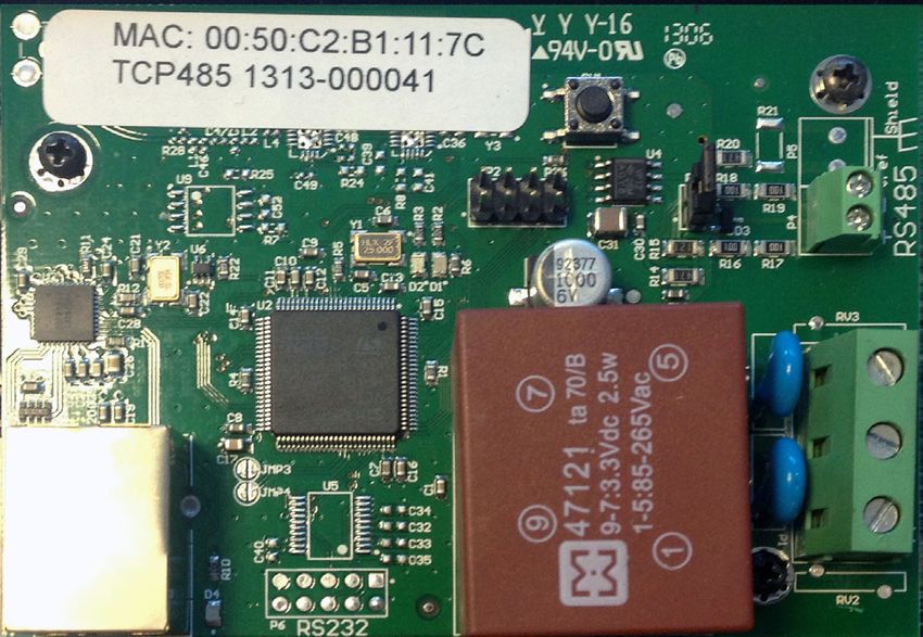
IT
    1        INDICE

1          INDICE                                                      3
2          CONFORMITA’                                                 4
           2.1       DICHIARAZIONE DI CONFORMITÀ (94/9/CE, All. VII)   4
3          AVVERTENZE GENERALI                                         4
4          ISTRUZIONI DI SICUREZZA                                     5
           4.1       NORME DI PRONTO SOCCORSO                          5
           4.2       NORME GENERALI DI SICUREZZA                       6
           4.3       IMBALLO                                           7
           4.4       CONTENUTO DELL’IMBALLO                            8
           4.5       IDENTIFICAZIONE MACCHINA E COSTRUTTORE            8
5          CARATTERISTICHE TECNICHE                                    9
6          DESCRIZIONE DEL PRODOTTO                                    9
7          INSTALLAZIONE                                               10
           7.1       FISSAGGIO A MURO                                  11
           7.2       CABLAGGI                                          11
           7.3       LED E CONNETTORI                                  13
           7.4       CONFIGURAZIONE                                    14
           7.5       NAVIGAZIONE                                       16
           7.6       NETWORK                                           16
           7.7       SYSTEM                                            17
           7.8       RS485                                             17
           7.9       PROCEDURA DI RESET E RIPRISTINO
                     IMPOSTAZIONI DI FABBRICA                          18
8          SMALTIMENTO                                                 19

M0270 IT                                                                    3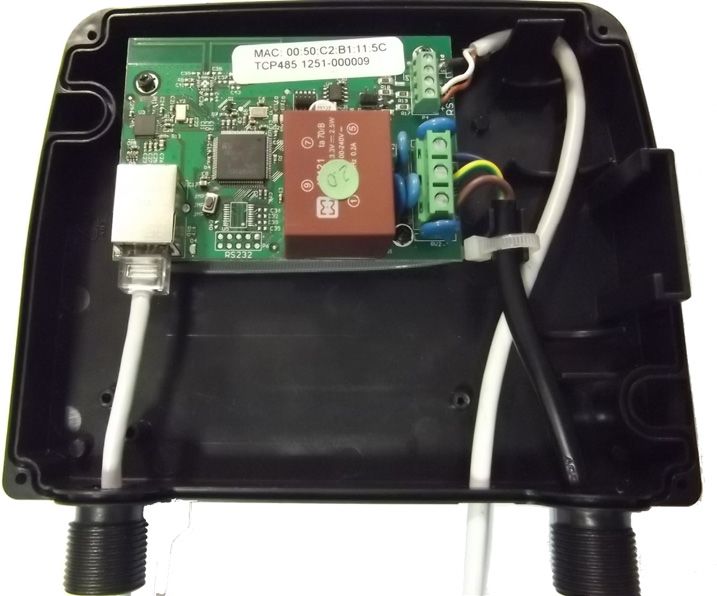
IT
     2        CONFORMITA’
         2.1            DICHIARAZIONE DI CONFORMITÀ                                      (94/9/CE, All. VII)
Il fabbricante:
PIUSI S.p.A
Via Pacinotti 16/A z.i. Rangavino
46029 Suzzara - Mantova - Italia
DICHIARA
sotto la propria responsabilità, che l’apparecchiatura descritta in appresso:
Descrizione : MODULO PW-LAN
Modello : PW-LAN
Matricola: riferirsi al Lot Number riportato sulla targa CE apposta sul prodotto
Anno di costruzione: riferirsi all’anno di produzione riportato sulla targa CE apposta
sul prodotto.
è conforme alle disposizioni legislative che traspongono le direttive :
- Direttiva Compatibilità Elettromagnetica 2004/108/CE
- Direttiva Bassa Tensione 2006/95/CE
La documentazione è a disposizione dell’autorità competente su motivata richie-
sta presso Piusi S.p.A. o richiedendola all’indirizzo e-mail: doc_tec@piusi.com
La persona autorizzata a costituire il fascicolo tecnico e a redigere la dichiarazione
è Otto Varini in qualità di legale rappresentante.

     Suzzara, 01/01/2013                         Otto Varini
                                                 legale rappresentante

     3        AVVERTENZE GENERALI
Avvertenze                 Per salvaguardare l’incolumità degli operatori, per evitare
importanti                 possibili danneggiamenti e prima di compiere qualsiasi
                           operazione, è indispensabile aver preso conoscenza di
                           tutto il manuale istruzioni.
Simbologia                 Sul manuale verranno utilizzati i seguenti simboli per evi-
utilizzata nel             denziare indicazioni ed avvertenze particolarmente impor-
manuale                    tanti:
                           ATTENZIONE
                           Questo simbolo indica norme antinfortunistiche per gli
                           operatori e/o eventuali persone esposte.
                           AVVERTENZA
                           Questo simbolo indica che esiste la possibilità di
                           arrecare danno alle apparecchiature e/o ai loro
                           componenti.
                           NOTA
                           Questo simbolo segnala informazioni utili.
Conservazio-               Il presente manuale deve essere integro e leggibile in
ne del ma-                 ogni sua parte, l’utente finale ed i tecnici specializzati
nuale                      autorizzati all’installazione e alla manutenzione, devono
                           avere la possibilità di consultarlo in ogni momento.
Diritti di ripro-          Tutti i diritti di riproduzione di questo manuale sono ri-
duzione                    servati alla Piusi S.p.A.
                           Il testo non può essere usato in altri stampati senza auto-
                           rizzazione scritta della © Piusi S.p.A.
                           IL PRESENTE MANUALE È PROPRIETÀ DELLA PIUSI S.p.A.
                           OGNI RIPRODUZIONE ANCHE PARZIALE E’VIETATA.

4                                                                                                      M0270 IT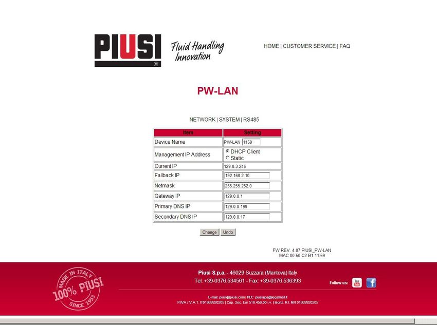
IT
   4       ISTRUZIONI DI SICUREZZA
       4.1       NORME DI PRONTO SOCCORSO
Persone colpi-    Staccare l’alimentazione, o usare un isolante asciutto
te da scariche    per proteggersi nell’operazione di spostamento dell’in-
elettriche        fortunato lontano da qualsiasi conduttore. Evitare
                  di toccare l’infortunato con le mani nude fino a che
                  quest’ultimo non sia lontano da qualsiasi conduttore.
                  Chiedere immediatamente l’aiuto di persone addestra-
                  te e qualificate. Non intervenire sugli interruttori a mani
                  bagnate.
NOTA              Fare riferimento alle schede di sicurezza del prodot-
                  to

M0270 IT                                                                        5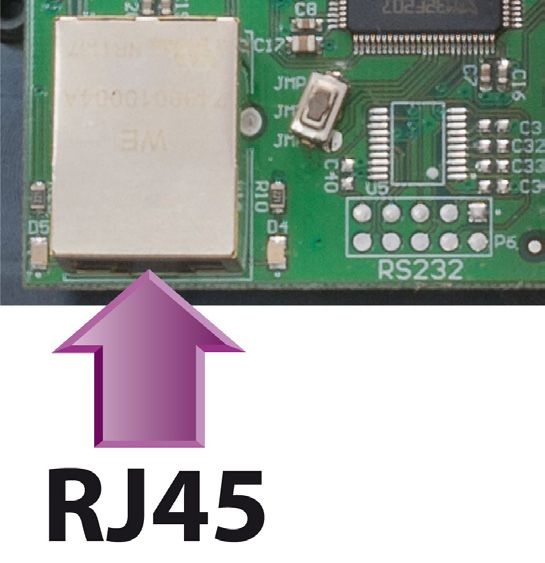
IT
       4.2           NORME GENERALI DI SICUREZZA
Caratteristiche            Indossare un equipaggiamento di protezione che sia:
essenziali dell’e-
quipaggiamento
di protezione

Dispositivi di
protezione
individuale da
indossare

                           manuale di istruzioni

PERICOLO                   Il Dispositivo NON è di tipo ANTI DEFLAGRANTE
                           Il dispositivo deve essere installato all’esterno di aree a
                           pericolo di esplosione
                           Non installare in zone ove possano essere presenti va-
                           pori infiammabili
PERICOLO                   Il dispositivo deve essere installato sotto una tettoia o
                           comunque in ambiente protetto dalla pioggia

ATTENZIONE                 Il dispositivo deve essere montato in verticale con i
                           passacavi rivolti verso il basso

PERICOLO                                                                            -
                           tola aperta e contatti elettrici accessibili. Tutte queste
                           operazioni devono essere fatte con apparecchio iso-
                           lato dalla rete elettrica per evitare pericoli di folgora-
                           zione!
                           Tutte le operazioni di istallazione elettrica devono
                           essere fatte da personale elettrotecnico o elettronico
                           qualificato.
                           Indossare guanti da elettricista.
ATTENZIONE                 Come norma generale di sicurezza elettrica si consiglia
                           sempre di alimentare il dispositivo proteggendo la
                           linea con :
                           - interruttore/sezionatore magnetotermico di portata
                           di corrente adeguata alla linea elettrica

                           da 30 mA
ATTENZIONE                 Ciascun dispositivo deve essere installato da personale
                           qualificato, autorizzato E responsabilità dell’istallatore
                           garantire che l’istallazione sia eseguita in conformità
                           alle Leggi e regolamenti locali

6                                                                                        M0270 IT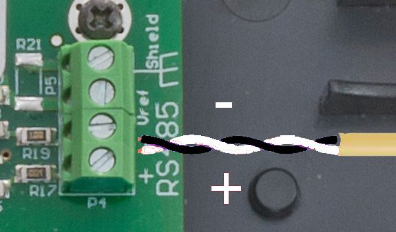
IT
ATTENZIONE                          L’apparecchio è destinato solo all’uso da parte di per-
                                    sonale professionale ed autorizzato

PERICOLO                            Le sezioni dei cavi devono essere adeguate alle portate
                                    di corrente del dispositivo
                                    Prolunghe non adatte possono risultare pericolose
                                    All’aperto utilizzare solo prolunghe autorizzate e pre-
                                    viste per quell’utilizzo, con sezione d conduzione suffi-
                                    ciente, in base alle normative vigenti
                                    Non toccare mai la spina e la presa con mani bagnate
                                    L’allacciamento tra spina e presa deve rimanere lon-
                                    tano dall’acqua.
                                    Prima di ogni utilizzo, controllare che il cavo di allac-
                                    ciamento non presentino danni. Far sostituire imme-
                                    diatamente il cavo di allaccio alla rete qualora risulti
                                    danneggiato.
ATTENZIONE                          La manutenzione delle parti elettriche puo’ essere ef-
                                    fettuata solo da personale elettrotecnico o elettronico
                                    qualificato.
                                    Indossare guanti da elettricista.
                                                                                            -
                                    care di staccare dalla linea elettrica il dispositivo per
                                    spegnerlo e isolarlo dalla rete elettrica.
                                    Qualora il dispositivo sia venduto senza cavo preve-
                                    dere verifica periodica del circuito di messa a terra in
                                    conformità alle norme vigenti.

      4.3                IMBALLO
Premessa                 L’apparecchio è fornito imballato in una scatola di carto-
                         ne sulla quale sono apposte le seguenti indicazioni:
1 - contenuto della
confezione
2 - peso del contenuto
3 - descrizione del
prodotto

M0270 IT                                                                                        7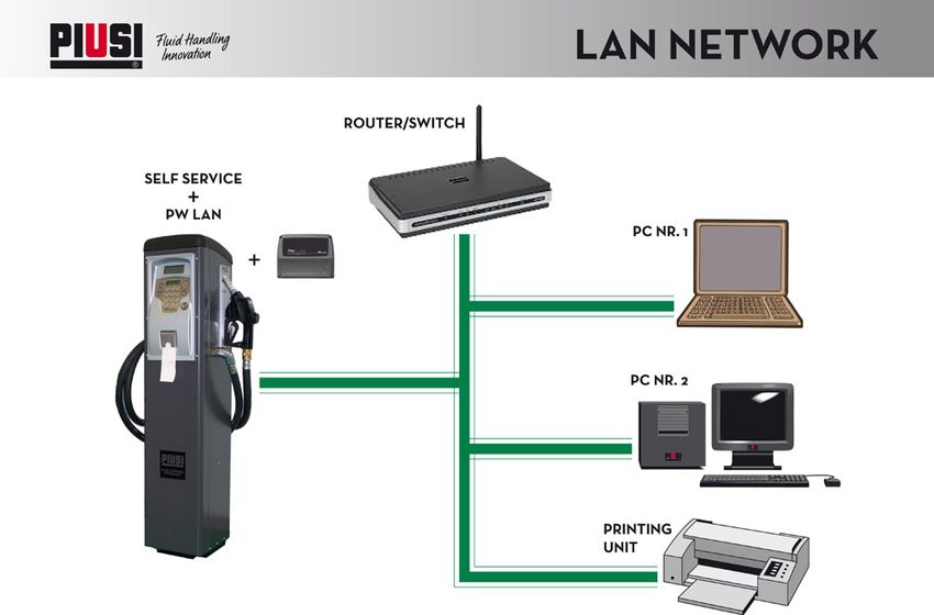
IT
4.4 CONTENUTO DELL’IMBALLO
Premessa Per aprire l’imballo, utilizzare delle forbici o un taglierino.
NOTA Nel caso in cui uno o più componenti di seguito de-
scritti non siano presenti all’interno della confezione,
contattare il servizio di assistenza tecnica Piusi S.p.A.
ATTENZIONE Verificare che i dati di targa corrispondano a quelli de-
siderati. Per qualsiasi anomalia, contattare immedia-
tamente il fornitore, segnalando la natura dei difetti e,
in caso di dubbio sulla sicurezza dell’apparecchiatura,
non utilizzarla.
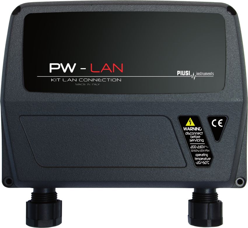
4.5 IDENTIFICAZIONE MACCHINA E COSTRUTTORE
Premessa PW-LAN è provvisto di DIVERSE TARGHE DI IDENTIFICAZIO-
NE APPLICATE SUL GUSCIO ESTERNO, CHE RIPORTANO LE
SEGUENTI INFORMAZIONI:
modello;
numero di lotto / Anno di costruzione;
dati tecnici;
ATTENZIONE Verificare sempre prima dell’installazione che il
modello sia corretto e adatto all’alimentazione
effettivamente disponibile (Tensione / Frequenza).
Occorre verificare che nel tempo la targa non si deteriori
o si stacchi.
NOTA Se dovesse verificarsi questa situazione preghiamo di
contattare il nostro ufficio assistenza per farvi spedire
le targhe rovinate o mancanti, per riapplicarle dove
previsto in origine.
LE TARGHE PRESENTI SONO LE SEGUENTI:
1 - Targa frontale 3 - Marchio CE
2 - Targa Dati Tecnici 4 - Targa CE /Lotto/Anno
PW - LAN
KIT LAN CONNECTION
MADE IN ITALY
1
WARNING
disconnect
before
servicing
3 4
100-240V
50-60Hz/ 15W I P54
operating
temperature
-20/+50°C 2
8 M0270 IT
IT
   5       CARATTERISTICHE TECNICHE
Dimensioni di massima
Lunghezza (A)                       180 mm
Profondità (B)                      60 mm
Altezza (C)                         160 mm
Peso                                330 g

Dati Tecnici
Voltaggio sistema di gestione       100 - 230 Vac
Frequenza                           50 Hz / 60 Hz
Potenza massima                     15 W
Grado di protezione                 IP54

   6       DESCRIZIONE DEL PRODOTTO
INTRODU-        PW-LAN è una nuova soluzione che permette di connettere diversi
ZIONE           prodotti Piusi ad una rete LAN.

                          Conversione istantanea di un segnale RS485 a
                          Ethernet
                          Funzione di IP Fallback
                          Compatibilità con tutti i DCHP server
                          Compatibile al 100% con i software Piusi
                Il PW-LAN è un dispositivo avanzato che possiede diverse moda-
                lità di conversione di segnale RS485, costruito su un interfaccia
                semplice e intuitiva.
                Questo manuale descrive il sistema operativo del PW-LAN, inte-
                grato nel dispositivo.
PRODOTTI        PW-LAN supporta i seguenti prodotti Piusi:
SUPPORTATI                Self Service FM
                          Self Service MC
                          Cube MC
                          MC-BOX
                          OCIO
                          MCO
REQUISITI DI SISTEMA
SISTEMI                   Microsoft Windows XP
OPERATIVI                 Windows Vista
COMPATIBILI               Windows 7
                          Windows 8
WEB                       Mozilla Firefox
BROWSER                   Apple Safari
COMPATIBILI               Google Chrome
                          Microsoft Internet Explorer 8 (o superiore)

M0270 IT                                                                            9
IT
     7   INSTALLAZIONE
ATTENZIONE    Le operazioni di installazione sono effettuate con
              scatola aperta e contatti elettrici accessibili. Tutte
              queste operazioni devono essere fatte con apparec-
              chio isolato dalla rete elettrica per evitare pericoli di
              folgorazione!
              Tutte le operazioni seguenti devono essere effettuate
              da personale elettrotecnico o elettronico specializzato
              È assolutamente vietato l’utilizzo di accessori inadatti
              e non forniti con il sistema. Piusi S.p.A. declina ogni
              responsabilità per danni a persone, cose o all’am-
              biente, dovuti alla mancata osservanza di questa
              prescrizione.
              INSTALLARE L’APPARECCHIO CON I PASSAGGI CAVI
              RIVOLTI VERSO IL BASSO E PREVEDERE UNA COPER-
              TURA DI PROTEZIONE.

10                                                                        M0270 IT
IT
7.1 FISSAGGIO A MURO
PREMESSA Rimuovere il coperchio frontale per eseguire il fissaggio di
PW-LAN a parete
Per il fissaggio a parete, utilizzare nr. 2 viti M4
13.5 156 10
35
80
Ø 4.5
25
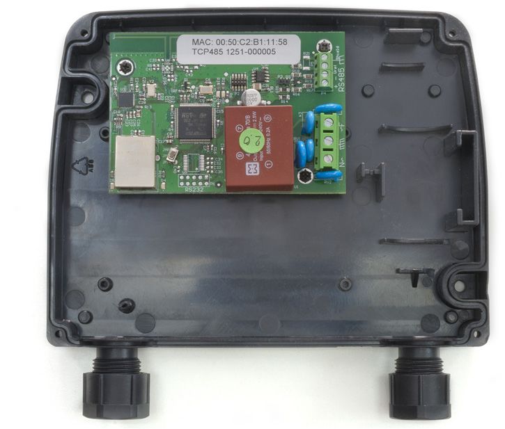
7.2 CABLAGGI
PREMESSA Rimuovere il coperchio frontale per eseguire i necessari cablaggi
Per effettuare un’operazione corretta seguire gli step successivi:
1 Collegare il cavo RS485 come mostrato sotto.
2 Collegare I 3 cavi di alimentazione come mostrato -
Input 100-240 Vac 50/60 Hz.
M0270 IT 11IT
3 Collegare il cavo LAN
ATTENZIONE CAVO RS485
Utilizzando un cavo certificato per rs485 si possono
raggiungere 1200 metri
CAVO ETHERNET
Utilizzare cavo schermato categoria 5 o superiore.
Distanza massima raggiungibile fino a 90 metri. La
distanza massima è influenzata anche dall’architettu-
ra di rete presente
PW-LAN
RS485
CABLATO
POWER
ETHERNET
ATTENZIONE Fissare il cavo di alimentazione con la fascetta in dotazio-
ne in modo che un eventuale distacco del cavo dai mor-
setti non porti a tensioni pericolose ad altri cavi connessi
con l’esterno.
12 M0270 ITIT
7.3 LED E CONNETTORI
3
1
D2 D1
4
2
D5
D4
1 Pulsante RESET di ripristino delle impostazioni di fabbrica
2 Connettore Ethernet
3 Connettore per RS485
4 Connettore di alimentazione 100/240Vac 50/60 Hz
LED LAMPEGGIO MESSAGGIO EQUIVALENTE
OFF Nessun dato da RS485
D1 SLOW
Trasmissione dati da RS485
FLASH
OFF DCHP IP personalizzato
disabilitato, (diverso da 192.168.2.10)
ON DHCP abilitato
D2 SLOW DCHP abili- nessun IP dal IP di sicurezza
FLASH tato, server DHCP 192.168.2.10
FAST DHCP Standard IP 192.168.2.10
FLASH disabilitato
D4 ON segnale LAN
D5 ON Power ON
M0270 IT 13IT
7.4 CONFIGURAZIONE
PREMESSA Questo è lo schema di una tipica rete LAN.
ACCESSO Per accedere alla configurazione del PW-LAN, segui-
re i seguenti passaggi:
1 Assicurarsi che il PC sia collegato via LAN al dispositivo
Piusi
2 Configurare la scheda Ethernet del PC con un IP statico
sulla subnet 192.168.2.x (es. Indirizzo IP: 192.168.2.150 e
maschera di sottorete: 255.255.255.0).
3 Configurare opzioni internet del browser SENZA server
proxy.
4 Lanciare il Web Browser sul PC. Inserire l’indirizzo IP di
default nella barra dell’indirizzo. Premere Enter.
Dispositivo Indirizzo IP di default
PW-LAN 192.168.2.10
5 Inserire admin come nome utente e piusipass come
Password , cliccare Login.
14 M0270 ITIT M0270 IT 15
IT
        7.5     NAVIGAZIONE
PREMESSA        L’interfaccia di configurazione del PW-LAN contiene tre scherma-
                te principali, ognuna di queste consente di configurare funziona-
                lità differenti del dispositivo Piusi.

NETWORK         La schermata “Network” consente di configurare la modalità di
                                                                            -

SYSTEM

RS485           La schermate“RS485”configura il sistema di conversione RS485,
                è possibile scegliere un prodotto Piusi o settare i parametri ma-
                nualmente.

        7.6     NETWORK
PREMESSA          La schermata Network consente di configurare i parametri TCP/IPv4
ITEM/                            1) Caso DHCP Client                                2) Caso IP Statico
SETTING

DEVICE NAME       Specifica l’hostname del dispositivo.
MANAGEMENT IP     Si sceglie la modalità di gestione dell’IP del dispositivo tra 2 opzioni :
ADDRESS           - DHCP Client che significa che nela rete aziendale esiste un DHCP server che assegna al PW-
                  LAN un IP dinamico, un indirizzo IP del Gateway e un indirizzo DNS al dispositivo
                  - Static che significa che l’amministratore di rete assegna al PW-LAN un IP statico fisso.
CURRENT IP        E’’l’indirizzo dinamico che viene assegnato automaticamente dal DHCP server della rete
                  aziendale al PW-LAN

16                                                                                                       M0270 IT
IT
FALLBACK IP E’l’indirizzo IP che di default viene associato al PW-LAN se accadono questi fatti :
- il PW-LAN è configurato come DHCP Client ma dopo un certo tempo dall’accensione il DHCP
server non è riuscito ad assegnare un IP dinamico ed allora
- il PW-LAN si autoconfigura con l’IP di FallBack
STATIC IP E’ l’lP statico che l’amministratore di rete inserisce manualmente nel campo IP
NETMASK Definisce il range di appartenenza di un dispositivo all’interno di una sottorete. La maschera
255.255.255.0 (o“/24”) è comunemente usata in molti network di classe C.
GATEWAY IP Tipicamente questo è l’indirizzo IP del host che fornisce la connessione a Internet. Può essere
un Router ADSL, un modem o un router WISP
PRIMARY DNS IP Specifica l’indirizzo DNS (Sistema dei Nomi a Dominio) primario del server.
SECONDARY Specifica l’indirizzo DNS secondario del server. Questo campo è opzionale e verrà usato solo
DNS IP nel caso in cui il DNS primario non dovesse rispondere
7.7 SYSTEM
PREMESSA La schermata System consente di modificare la password per l’account
administrator.
NEW PASSWORD / VE- Inserire la nuova password per l’account administrator
RIFY NEW PASSWORD Re-inserire la password per l’account administrator
7.8 RS485
PREMESSA La schermata RS485 consente di configurare il sistema di conversion RS485
1) Caso scelta Prodotti Piusi 2) Caso Altri prodotti
Configurazione Default e scelta altri prodotti PIUSI Setting altri Parametri RS485
PIUSI Configurazione automatica dei prodotti Piusi. Scegliere un prodotto dalla lista
PRODUCT
CUSTOM PRO- Inserimento manuale dei parametri RS485
DUCT Procedura a quattro step:
1 Scegliere il Baudrate
2 Scegliere i Databit
3 Scegliere la Parità
4 Scegliere i Bit di stop
M0270 IT 17IT
7.9 PROCEDURA DI RESET E RIPRISTINO
IMPOSTAZIONI DI FABBRICA
Qualora non si riesca più ad accedere al dispositivo e si vogliano riportare le condi-
zioni di default fabbrica su di esso va applicata una particolare procedura di Reset
Hardware
ATTENZIONE La procedura deve essere effettuata solo da perso-
nale esperto ed istruito sui pericoli della corrente
elettrica!
Il personale deve indossare guanti isolanti al fine di
prevenire qualunque rischio di folgorazione!
La procedura è la seguente:
1) Togliere tensione di alimentazione al dispositivo
2) Aprire con le 4 viti la scatola
3) Individuare il pulsante RESET sulla scheda come illustra-
to nei paragrafi precedenti
4) Tenere premuto il pulsante RESET mentre si ridà alimen-
tazione
ATTENZIONE Questa fase è la più pericolosa perché si è in vicinanza
di punti in tensione pericolosa sulla scheda! Utilizzare
guanti isolanti da elettricista!
18 M0270 ITIT
8 SMALTIMENTO
Premessa In caso di demolizione del sistema, le parti di cui è
composto devono essere affidate a ditte specializzate
nello smaltimento e riciclaggio dei rifiuti industriali e, in
particolare:
Smaltimento L’imballaggio è costituito da cartone biodegradabile
dell’imballaggio che può essere consegnato alle aziende per il normale
recupero della cellulosa.
Smaltimento delle Le parti metalliche, sia quelle verniciate, sia quelle
parti metalliche in acciaio inox sono normalmente recuperabili dalle
aziende specializzate nel settore della rottamazione dei
metalli.
Smaltimento dei Devono obbligatoriamente essere smaltite da aziende
componenti elet- specializzate nello smaltimento dei componenti
trici ed elettronici elettronici, in conformità alle indicazioni della direttiva
2002/96/CE (vedi testo direttiva nel seguito).
Informa- La direttiva Europea 2002/96/EC richiede che le
zioni apparecchiature contrassegnate con questo simbolo
relative sul prodotto e/o sull’imballaggio non siano smaltite
all’ambien- insieme ai rifiuti urbani non differenziati. Il simbolo
te per i indica che questo prodotto non deve essere smaltito
clienti residenti insieme ai normali rifiuti domestici. E’ responsabilità
nell’unione del proprietario smaltire sia questi prodotti sia le altre
europea apparecchiature elettriche ed elettroniche mediante le
specifiche strutture di raccolta indicate dal governo o
dagli enti pubblici locali.
Smaltimento di Ulteriori parti costituenti il prodotto, come tubi,
ulteriori parti guarnizioni in gomma, parti in plastica e cablaggi, sono
da affidare a ditte specializzate nello smaltimento dei
rifiuti industriali.
M0270 IT 19EN
1 INDEX
1 INDEX 21
2 CONFORMITY 22
2.1 DECLARATION OF CONFORMITY (94/9/CE, All. VII) 22
3 GENERAL WARNINGS 22
4 SAFETY INSTRUCTIONS 23
4.1 FIRST AID RULES 23
4.2 GENERAL SAFETY RULES 24
4.3 PACKAGING 25
4.4 PACKAGE CONTENTS/PRE-INSPECTION 26
4.5 MACHINE AND MANUFACTURER IDENTIFICATION 26
5 TECHNICAL FEATURES 27
6 OVERVIEW 28
7 INSTALLATION 28
7.1 FIXING TO THE WALL 29
7.2 WIRE CONNECTION 29
7.3 LED & CONNECTORS 31
7.4 GETTING STARTED 32
7.5 NAVIGATION 34
7.6 NETWORK TAB 34
7.7 SYSTEM TAB 35
7.8 RS485 TAB 35
7.9 PROCEDURE TO RESTORE
FACTORY SETTINGS 36
8 DISPOSAL 37
M0270 EN 21EN
2 CONFORMITY
2.1 DECLARATION OF CONFORMITY (94/9/CE, All. VII)
The Manifacturer:
PIUSI S.p.A
Via Pacinotti 16/A z.i. Rangavino
46029 Suzzara - Mantova - Italia
HEREBY STATES under its own responsibility, that the equipment described
below:
Description: PW-LAN module
Model : PW-LAN
Serial number: refer to Lot Number shown on CE plate affixed to product
Year of manufacture: refer to the year of production shown on the CE plate af-
fixed to the product
is in conformity with the legal provisions indicated in the directives:
- Electromagnetic Compatibility Directive 2004/108/EC
- Low-Voltage Directive 2006/95/EC
The documentation is at the disposal of the competent authority following
motivated request at Piusi S.p.A. or following request sent to the email address:
doc_tec@piusi.comThe person authorised to compile the technical file and draw
up the declaration is Otto Varini as legal representative.
Suzzara, 01/01/2013 Otto Varini
legal representative.
3 GENERAL WARNINGS
Important To ensure operator safety and to protect the pump
precautions from potential damage, workers must be fully acquaint-
ed with this instruction manual before performing any
operation.
Symbols used The following symbols will be used throughout the
in the manual manual to highlight safety information and precautions
of particular importance:
ATTENTION
This symbol indicates safe working practices for opera-
tors and/or potentially exposed persons.
WARNING
This symbol indicates that there is risk of damage to the
equipment and/or its components.
NOTE
This symbol indicates useful information.
Manual pres- his manual should be complete and legible throughout.
ervation It should remain available to end users and specialist
installation and maintenance technicians for consulta-
tion at any time.
Reproduction All reproduction rights are reserved by Piusi S.p.A. The
rights text cannot be reprinted without the written permis-
sion of Piusi S.p.A.
THIS MANUAL IS THE PROPERTY OF Piusi S.p.A.
ANY REPRODUCTION, EVEN PARTIAL, IS FORBIDDEN.
22 M0270 ENEN
4 SAFETY INSTRUCTIONS
4.1 FIRST AID RULES
Persons who Disconnect the power source, or use a dry insulator to
have suffered protect yourself while you move the injured person
electric shock away from any electrical conductor. Avoid touching
the injured person with your bare hands until he is far
away from any conductor. Immediately call for help
from qualified and trained personnel. Do not operate
switches with wet hands.
NOTE Please refer to the safety data sheet for the product
M0270 EN 23EN
4.2 GENERAL SAFETY RULES
Essential Wear protective equipment that is:
protective
equipment
characteristics
Personal
protective
equipment that
must be worn
instructions manual
DANGER The Device is not an anti-explosive type
The device must be installed outside areas at risk of
explosion
Do not install in areas where flammable vapors may
be present
DANGER The device must be installed under a roof or in any
environment, protected from rain
ATTENTION The device must be mounted vertically with the grom-
mets facing down
DANGER Installation operations are carried out with the box
open and accessible electrical contacts. All these ope-
rations have to be done with the unit isolated from the
power supply to prevent electrical shock!
All work related to electrical installation must be per-
formed by qualified installer electrical or electronic.
Wear insulated gloves for electrician.
ATTENTION As a general rule of electrical safety is always recom-
mended to power the device protecting the line with:
- Switch / breaker with adeguate ampacity to the
power line
- RCD (Residual Current Device) of 30 mA
ATTENTION Devices must be professionally installed by qualified
and authorized installer and it is the professional instal-
ler’s responsibility to make sure the device is operated
within local country law and regulatory requirements
ATTENTION The device is intended for use only by professional
staff and authorized
24 M0270 ENEN
DANGER The cable must be adapted to the current capacities
of the device.
Never touch the plug and socket with wet hands
Unsuitable extension cable can be dangerous.
In accordance with current regulation only extension
cable that are labelled for outdoor use and have a suf-
ficient ampacity should be used outdoor
The connection between plug and socket must stay
away from water.
Before each use, check that the power cable for da-
mage. Replace immediately the cable connection to
the network if it is damaged.
ATTENTION The maintenance of the electrical parts can ‘be done
only by qualified installer electrical or electronic.
Wear insulated gloves for electrician.
Before performing any maintenance make sure to
unplug the device from the power supply to turn it off
and isolate it from the mains.
If the device is sold without cable to provide periodic
verification of the circuit grounding in accordance
with current regulations.
4.3 PACKAGING
FOREWORD The appliance comes packed in a cardboard box bearing
the following markings:
1 - contents of the
package
2 - weight of the con-
tents
3 - description of the
product
M0270 EN 25EN
4.4 PACKAGE CONTENTS/PRE-INSPECTION
FOREWORD To open the packaging, use a pair of scissors or a cutter, being
careful not to damage the dispensing system or its components.
NOTES In the event that one or more of the components de-
scribed below are missing from inside the package,
please contact Piusi inc technical support.
WARNING Check that the data on the plate correspond to the
desired specifications. In the event of any anomaly,
contact the supplier immediately, indicating the nature
of the defects. Do not use equipment which you suspect
might not be safe.
4.5 MACHINE AND MANUFACTURER IDENTIFICATION
FOREWORD PW-LAN
attached externally and contains the following in-
formation:
model
ATTENTION Before installing, always make sure the type of
dispensing system is correct and suitable for the
available power supply (Voltage/Frequency.)
Make sure that the plate does not deteriorate or be-
come detached over time.
NOTE Should this situation arise, please contact our
support department and arrange to have the
damaged or missing plates sent back and replaced
where necessary.
The plates are the following:
1 - Front plate 3 - CE mark
2 - Technical Data Plate 4 - CE plate /Lot/Year
PW - LAN
KIT LAN CONNECTION
MADE IN ITALY
1
WARNING
disconnect
before
servicing
3 4
100-240V
50-60Hz/ 15W I P54
operating
temperature
-20/+50°C 2
26 M0270 ENEN 5 TECHNICAL FEATURES Dimensions Length (A) 180 mm Depth (B) 60 mm Height (C) 160 mm Weight 330 g Technical Specifications Voltage 100 - 230 Vac Frequency 50 Hz / 60 Hz Max. power 15 W Protection grade IP54 M0270 EN 27
EN
 6        OVERVIEW
Introduction Welcome to PW-LAN – the new solution which allows you to
             connect Piusi devices to your LAN network.
             The PW-LAN provides:
                       Instant conversion from RS485 to Ethernet signal
                       IP Fallback function
                       DHCP compatible
                       100% compatibility with Piusi Softwares
             The PW-LAN is an advanced device capable of powerful and
             different signal conversion features, built upon a simple and
             intuitive user interface foundation.
             This User Guide describes the PW-LAN operating system version
             3.0, which is integrated into the device.
Supported    PW-LAN supports the following Piusi products:
Products               Self Service FM
                       Self Service MC
                       Cube MC
                       MC-BOX
                       OCIO
                       MCO
SYSTEM REQUIREMENTS
OPERATING              Microsoft Windows XP
SYSTEM                 Windows Vista
                       Windows 7
                       Windows 8
WEB                    Mozilla Firefox
BROWSER                Apple Safari
                       Google Chrome
                       Microsoft Internet Explorer 8 (or above)

 7        INSTALLATION
ATTENTION             The installation operations are performed with
                      door open and power contacts accessible. All these
                      operations must be performed with the appliance
                      isolated from the power mains to avoid any risk of
                      electric shocks!
                      All the following operations must be performed by
                      skilled electro-technical or electronic experts
                      The use of accessories that are unsuitable and were
                      not provided with the system is strictly prohibited.
                      Piusi S.p.A. accepts no responsibility for damage
                      to persons, property or the environment caused by
                      failure to comply with this requirement.
                      INSTALL THE APPLIANCE WITH CABLE GLANDS FACING DOWN
                      AND PROVIDE A PROTECTIVE COVER.

28                                                                           M0270 EN
EN
7.1 FIXING TO THE WALL
FOREWORD Remove the front cover to fix the PW-LAN on the wall
To fix on the wall, use No. 2 M4 screws
13.5 156 10
35
80
Ø 4.5
25
7.2 WIRE CONNECTION
FOREWORD Removing the frontal case it is possible to make all the
necessary wiring .
To do a proper operation, perform the following steps:
1 Fix the the RS485 twisted cable as shown below.
2 Fix the three power supply cable as shown below -
Input 100-240 Vac 50/60 Hz.
M0270 EN 29EN
3 Plug in the Ethernet cable
ATTENTION RS485 CABLE
Using a certified cable for rs485 you can reach 1200 meters
ETHERNET CABLE
Use a shielded cable, category 5 or higher. The max. distance
that can be reached is 90 metres. The maximum distance is
also affected by the existing network architecture
WIRED PW-LAN
RS485
POWER
ETHERNET
ATTENTION Fix the power cord with the clip provided so that any separation
of the cable from the terminals does not lead to dangerous vol-
tages other cables connected to the outside.
30 M0270 ENEN
7.3 LED & CONNECTORS
3
1
D2 D1
4
2
D5
D4
1 RESET button to restore factory defaults
2 Ethernet connector
3 RS485 connector
4 Power 100/240Vac 50/60 Hz connector
LED FLASHING EQUIVALENCE
OFF No traffic from RS485
D1 SLOW
Traffic from RS485
FLASH
DCHP Disabled, Customized
IP (different
OFF
from 192.168.2.10)
ON DHCP Enabled
D2 SLOW
DCHP Enabled, No IP from
Fallback IP
FLASH DHCP server 192.168.2.10
FAST DHCP Disabled Standard IP 192.168.2.10
FLASH
D4 ON LAN signal
D5 ON Power ON
M0270 EN 31EN
7.4 GETTING STARTED
FOREWORD This is the scheme of a typical site structure.
ACCESS To access the PW-LAN Configuration Interface, perform the
following steps
1 Make sure that your host machine is connected via Ethernet to
the Piusi device
2 Configure the Ethernet adapter on your computer with a static
IP address on the 192.168.2.x subnet (for example, IP address:
192.168.2.150 and subnet mask: 255.255.255.0).
3 Configure internet options of your browser WITHOUT proxy
server
4 Launch your Web browser. Enter the default IP address of your
device in the address field. Press Enter (PC) or Return (Mac).
Device Default IP Address
PW-LAN 192.168.2.10
5 Enter admin in the Username and piusipass in the Pass-
word fields and click Ok.
32 M0270 ENEN M0270 EN 33
EN
 7.5 NAVIGATION
FOREWORD        The PW-LAN Configuration Interface contains three main tabs, each of
                them provides a Web-based management page to configure a speci-
                fic aspect of the Piusi device:

NETWORK
                Secondary DNS Server.
SYSTEM          The“System Tab”. controls administrator account management,
                firmware update, and configuration backup.
RS485           The“RS485 Tab” configures the RS485 conversion system, it is pos-
                sibile to choose a Piusi product or to set the parameters manually.

 7.6 NETWORK TAB
                  The Network tab allows to configure TCP/IPv4 parameters.
                                 1) Case DHCP Client                                   2) Case Static IP
ITEM/
SETTING

DEVICE NAME       Specifies the host name
MANAGEMENT IP     You chooses the formality of management of the IP of the device among 2 options:
ADDRESS           - DHCP Client that it means that in the lan network exist a DHCP server that assigns a dynamic
                  IP to the PW-LAN , an address IP of the Gateway and an address DNS to the device
                  - Static that means that the administrator of net assigns a fixed static IP to the PW-LAN.
CURRENT IP        it is the dynamic address that is automatically assigned by the DHCP file server of the lan network to
                  the PW-LAN
FALLBACK IP       it is the address IP that of default is associated to the PW-LAN if these facts happen:
                  - the PW-LAN is configured as DHCP Client MA
                  - after a certain time from the turning of the device the DHCP file server has not succeeded in assign-
                  ing a dynamic IP and then the PW-LAN configure itself with the IP of FallBack
34                                                                                                          M0270 EN
EN
STATIC IP it is the static lP that the administrator of net manually inserts in the field IP
NETMASK When the netmask is expanded into its binary form, it provides a mapping to define which portions
of the IP address range are used for the network devices and which portions are used for host de-
vices. The netmask defines the address space of the device’s network segment. The 255.255.255.0 (or
“/24”) netmask is commonly used on many Class C IP networks.
GATEWAY IP Typically, this is the IP address of the host router, which provides the point of connection to
the Internet. This can be a DSL modem, cable modem, or WISP gateway router. The device
directs data packets to the gateway if the destination host is not within the local network.
PRIMARY DNS IP Specify the IP address of the primary DNS (Domain Name System) server.
SECONDARY Specify the IP address of the secondary DNS server. This entry is optional and used only if the primary
DNS IP DNS server is not responding
7.7 SYSTEM TAB
FOREWORD The“SystemTab”controls the administrator account management.
NEW PASSWORD Enter the new password for the administrator account.
VERIFY NEW PASSWORD Re-enter the new password for the administrator account.
7.8 RS485 TAB
FOREWORD The “RS485 Tab” configures the RS485 conversion system
1) Case choice Products Piusi 2) Case Other products
Configuration Default and choice other products PIUSI Setting others Parameters RS485
PIUSI PRODUCT PIUSI PRODUCT: Preset configuration. Choose one of the prod-
ucts in the list.
MANUAL CONFIGURATION Manually enter the RS485 parameters.
CUSTOM This is a four-step procedure:
PRODUCT 1 Choose the Baudrate
2 Choose Databit
3 Choose the Parity
4 Choose Bit Stop
M0270 EN 35EN
7.9 PROCEDURE TO RESTORE
FACTORY SETTINGS
If you are no longer able to access the device and you want to reset the
factory settings, a special Reset procedure should be applied.
ATTENTION The procedure must be done only by staff experi-
enced on the dangers of the electrical power!
The staff must wear insulating gloves in order
to
The procedure is as fo lplorwevse:
1) Remove supply voltage to the device
2) Open the box with the 4 screws
3) Locate the RESET button
as shown in the previous paragraphsi
4) Press and hold the RESET button while you
power
ATTENTION This procedure is very dangerous because you are near points
with dangerous voltage on the board.
Use insulating gloves for electricians!
36 M0270 EN8 DISPOSAL
Foreword If the system needs to be disposed, the parts which make
it up must be delivered to companies that specialize in the
recycling and disposal of industrial waste and, in particular:
Disposing of pack- The packaging consists of biodegradable cardboard which
ing materials can be delivered to companies for normal recycling of cel-
lulose.
Metal Parts Dis- Metal parts, whether paint-finished or in stainless steel, can
posal be consigned to scrap metal collectors.
Disposal of electric These must be disposed of by companies that specialize in
and electronic the disposal of electronic components, in accordance with
components the indications of directive 2002/96/CE (see text of directive
below).
Informa- European Directive 2002/96/EC requires that all equipment
tion regard- marked with this symbol on the product and/or packaging
ing the en- not be disposed of together with non-differentiated urban
vironment waste. The symbol indicates that this product must not be
for clients disposed of together with normal household waste. It is the
residing responsibility of the owner to dispose of these products
within the Euro- as well as other electric or electronic equipment by means
pean Union of the specific refuse collection structures indicated by the
government or the local governing authorities.
Miscellaneous Other components, such as pipes, rubber gaskets, plastic
parts disposal parts and wires, must be disposed of by companies special-
ising in the disposal of industrial waste.Piusi S.p.A.
Suzzara - Mantova (Italy)
M0270 ITEN_00Puoi anche leggere