Sistemi con pompa di calore - Heat pump systems
←
→
Trascrizione del contenuto della pagina
Se il tuo browser non visualizza correttamente la pagina, ti preghiamo di leggere il contenuto della pagina quaggiù

Sistemi con pompa
   di calore
  Heat pump systems

sistemi con pompa di calore
heat pump systems
indice/contents
                                                                 Filosofia MyClima / MyClima philosophy          04
                                                                          Sinottico di gamma / Our range
                                                                               Gamma prodotti / Products         06
                                                                                  Gamma sistemi / Systems        07

                                                      SISTEMI GEOTERMICI / GEOTHERMAL SYSTEMS

                                                 Cos’è l’energia geotermica / What is geothermal energy?         08

                            Pompe di calore da centrale termica / Heat pumps for thermal power station           12
                                                                                         GEO HF 6-33             12
                                                                                      GEO HF 40-100              14
                                                                                       GEO ADV PLUS              16
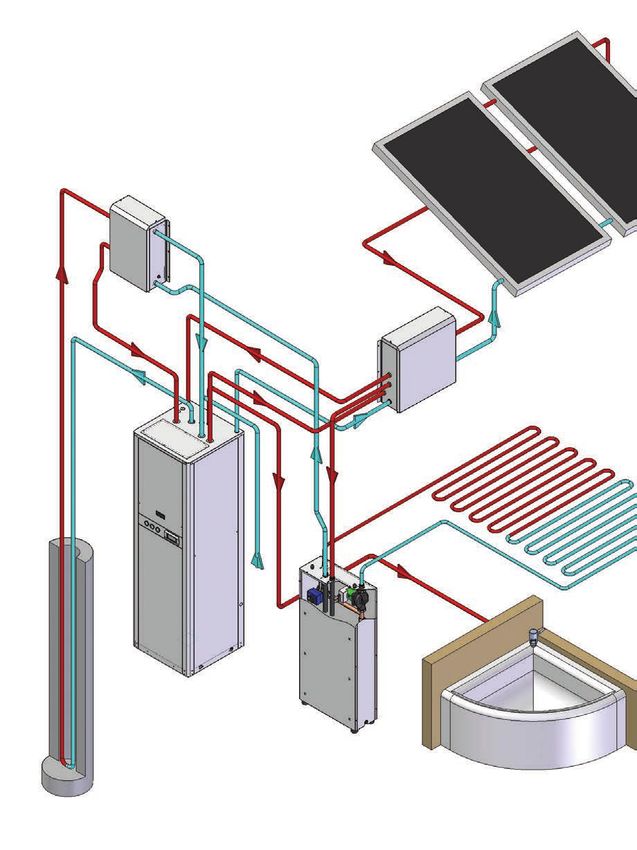
                                                                      Schema d’impianto / Layout plant           18
                                                                                    GEO EASY HT/HTR              20
                                                                      Schema d’impianto / Layout plant           22

                                                    Pompe di calore residenziale / Residential heat pumps        24
                                                                                                  DOMUS          24
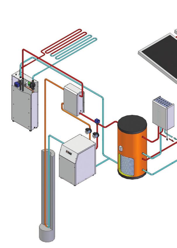
                                                                        Schema d’impianto / Layout plant         26

                                                         SISTEMI ARIA-ACQUA/ AIR-WATER SYSTEMS

            Come funziona una pompa di calore aria-acqua / How does an air-water heat pump work?                 28
                                                                       Gamma prodotti / Products                 29

                                Sistema integrato per il riscaldamento, raffrescamento e produzione ACS
                                            Integrated system for heating, cooling and DHW production
                                                                           SISTEMA IDEA / IDEA SYSTEM            30
                                                                       Schema d’impianto / Layout plant          32

Pompa di calore aria-acqua per produzione efficiente di ACS / Air-water heat pump for efficient DHW production
                                                                                                    EOS PLUS     34

                                                                     SISTEMI IBRIDI / HYBRID SYSTEMS

                                                                       SISTEMA IANUS / IANUS SYSTEM              36
                           Che cosa si intende per “Sistema ibrido”? / What does “Hybrid system” mean?           36

                                 Soluzioni proposte con sistema ibrido / Hybrid system plant solutions           38
                                    Sistema misto con pannello fotovoltaico termico e sonda geotermica           42
                                        Integrated system with thermal PV/T panel and geothermal probe

                                                               ACCESSORI PER IMPIANTI GEOTERMICI                 43
                                                             ACCESSORIES FOR GEOTHERMAL PLANTS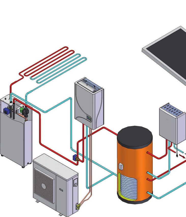
Filosofia MyClima
                                     MyClima Philosophy

04

     Perché scegliere un             Innovazione, sicurezza, semplicità, rispetto per l’ambiente:
     impianto di                     le 4 parole chiave che guidano il gruppo
     riscaldamento
     geotermico per la               L’azienda, giovane e dinamica, unisce l’esperienza del gruppo Fiorini, che da oltre trent’anni opera nel
     nostra casa?                    settore idrotermosanitario, ad un forte impulso per l’innovazione, che in Italia la rende pioniera in un
     ...per cinque buone             settore che è ancora agli albori.
     ragioni:                        Forte di questo, MyClima non propone solo una pompa di calore, ma un “sistema”. L’obiettivo è realizzare
                                     un impianto completo, ogni tassello che lo compone viene selezionato con cura ed ogni componente si
     • il risparmio energetico
                                     integra con gli altri per una risposta rapida e flessibile che garantisca il massimo grado di comfort ed
                                     efficienza. Le applicazioni sono svariate: riscaldamento invernale, raffrescamento estivo, produzione
     • la semplicità di gestione
                                     efficiente di acqua calda sanitaria, dalla singola villetta al complesso industriale.
     • il rispetto per l’ambiente
                                     Il punto di forza è la conoscenza a 360° delle tecnologie su fonti rinnovabili, che consente la
     • l’indipendenza dai
                                     progettazione e la realizzazione di impianti integrati destinati allo sfruttamento e l’integrazione di diverse
     combustibili fossili
                                     fonti energetiche, quali geotermia, aerotermia, solare termico, fotovoltaico etc.
     • la flessibilità del sistema

                                     Il cuore del sistema: la pompa di calore
     Why choosing
     geothermal heating for          Il cuore del sistema è la pompa di calore, totalmente progettata e realizzata internamente, l’ampia
     our home?                       gamma di potenze permette di coprire ogni tipo di esigenza. La grande competenza tecnica garantisce
     ... for five good               un’eccellente assistenza in tutte le fasi, dalla valutazione sulla fattibilità progettuale, all’analisi
     reasons:                        dell’investimento con piani di ammortamento mirati, fino ovviamente al dimensionamento dell’impianto,
                                     l’avviamento e l’assistenza post vendita. Il sistema è standardizzato ma personalizzabile; il cliente è un
     • energy savings                partner e le informazioni tecniche sul suo impianto vengono conservate per consentire in qualsiasi
     • ease of use                   momento di aggiungere componenti al variare delle esigenze.
     • environmentally friendly
                                     Il cervello di sistema: controllo continuo e semplice gestione
     • independence from fossil
     fuels
     • system flexibility
                                     Il cervello del sistema è il software di controllo e regolazione, anch’esso nato dall’esperienza interna dei
                                     tecnici del gruppo. Il sistema di controllo permette di gestire l’impianto e monitorare il corretto
                                     funzionamento di tutti i componenti idraulici e meccanici. La pompe di calore della serie GEO HF e ADV
                                     plus sono gestite da microprocessori dotati di Galileus, il fiore all’occhiello, un software specificamente
                                     implementato da MyClima che, oltre a sovrintendere tutte le modalità operative della macchina, mantiene
                                     monitorato tutto il sistema di climatizzazione e di produzione sanitaria; si tratta quindi di un sistema
                                     integrato in grado di gestire autonomamente i terminali di un impianto radiante, la deumidificazione degli
                                     ambienti, l’integrazione di un eventuale impianto solare termico. E’ possibile inoltre la gestione del free-
                                     cooling durante le stagioni intermedie. Tutte le funzioni di Galileus possono essere gestite tramite il
                                     pannello con display a cristalli liquidi che segnala le modalità di funzionamento impostate e le eventuali
                                     anomalie del sistema, la regolazione ed il controllo possono essere gestiti anche in remoto attraverso un
                                     apposito kit che permette di verificare e modificare i parametri di utilizzo comodamente dal proprio pc o
                                     dal centro assistenza.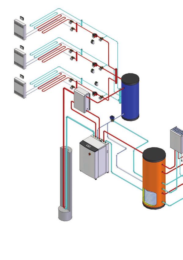
05

Innovation, safety, ease of use, environmentally friendly: 4 key words driving the group

A young and dynamic company combining the experience of the Fiorini group that has been working in
the HVAC field for over thirty years and a strong impetus for innovation, which makes it a pioneer in an
industry that is still in its infancy.
Building on this, MyClima not only offers heat pumps, but “systems”. The goal is to provide a complete
system in which each element is carefully selected and the components are perfectly integrated
altogether to provide a quick and flexible response ensuring the highest level of comfort and efficiency.
The applications are varied: winter heating, summer cooling, efficient production of domestic hot water,
from a single house up to an industrial complex.
Our strength is a comprehensive knowledge of renewable energy technologies, which allows to design and
build integrated systems aimed at exploiting and integrating various energy sources such as geothermal,
aerothermal, solar thermal, photovoltaic, etc..

The heart of the system: the heat pump

The heart of the system is the heat pump, which is entirely designed and manufactured in-house: the
wide range of powers allows to satisfy every need. The high technical expertise ensures excellent support
at all stages, from project feasibility assessment and investment analysis with targeted amortization
schemes to system design, commissioning and after-sales service. Despite being standardized, the system
can be customized. Every customer is our partner. We keep the technical information of our customers’
systems to add further components, at any time, based on changing needs.

The brain of the system: continuous monitoring and easy management

The brain of the system is the control and adjustment software, stemming from the experience of our
internal technicians. The control system allows to manage and to monitor the correct operation of all
hydraulic and mechanical components. The GEO HF and ADV plus series heat pumps are operated by
microprocessors equipped with our flagship software Galileus, which has been specially implemented by
MyClima not only to supervise all machine operational modes, but also to monitor the whole air
conditioning and DHW production system. It is an integrated system capable of independently managing
the terminals of a radiant system, ambient dehumidification and the integration of a solar thermal
system. It also allows to control free cooling during intermediate seasons. All Galileus functions can be
managed through the LCD panel supplied with it, which indicates the set operation mode and any system
malfunctioning. Adjustment and control can also be remotely managed through a special kit that lets you
conveniently check and change ant operation parameters from your own computer or from the service
centre.
Sinottico di gamma
Our range
06
Pompe di calore
Pompe di calore geotermiche
aria - acqua
Geothermal heat pumps
Air-water heat pumps
Prodotti Geo hf Geo hf Geo adv plus Domus Easy htr Easy ht Idea Eos plus
Products kW 5.7 - 27 kW 32.2 - 86.4 kW 6.3 - 30.5 kW 6.1 - 14.1 kW 5.7 - 28.4 kW 5.7 - 28.4 kW 3.0 - 16 kW 1,73
Per il dettaglio sulle caratteristiche
degli accessori vedi da pag.43
For details of the accessory
characteristics see from pag.43
Tipologia/Tipology
Riscaldamento +
Riscaldamento
Riscaldamento + Raffreddamento + ACS Raffreddamento ACS ACS
Funzioni/Functions ACS
Heating + Cooling + DHW Heating + Cooling DHW
Heating + DHW + DHW
Geotermia o Pozzo Aria
Geotermia o Pozzo Aria
Sorgente/Source Geothermal probe Canalizzabile
Geothermal probe or Well Air
or Well Air Duct
Circuito idraulico/Hydraulic circuit
Geotermico/Geothermal Inverter pumps On-off pumps On-off pumps Optional Optional Optional - -
Pozzo/Well Valvola modulante Valvola modulante Valvola modulante Valvola modulante Optional Optional - -
Impianto/Plant Inverter pumps On-off pumps On-off pumps On-off pumps Optional Optional On-off pumps -
Sanitario/Sanitary Inverter pumps On-off pumps On-off pumps On-off pumps - - On-off pumps On-off pumps
Produzione sanitario/Sanitary production
Circuito dedicato Circuito dedicato Circuito dedicato Circuito dedicato
Optional Optional
fino a 65°c fino a 65°c fino a 55°c fino a 58°c fino a 55 °C fino a 60 °C
ACS/DHW fino a 65 °C fino a 65 °C
Dedicated circuit up Dedicated circuit up Dedicated circuit up Dedicated circuit up Up to 55°C Up to 60°C
Optional up to 65°C Optional up to 65°C
to 65°C to 65°C to 55°C to 58°C
integrato/integrated integrato/integrated
Termoaccumulo/Storage tank Optional Optional Optional Optional Optional Optional
180 l. 300 l.
Caratteristiche/Characteristics
Regolazione/Regulation Galileus Galileus Galileus Galileus Tolomeus Tolomeus MyEnergy MyEnergy
Master/Slave 5 5 5 5 - - - -
COP 4,3 4,3 4 4,3 4,3 4,3 4,1 3,7
Rotativo
Scroll alta efficienza Scroll alta efficienza Scroll alta efficienza Scroll alta efficienza Scroll alta efficienza Scroll alta efficienza Rotativo
Tipo compressore/Compressor type DC Inverter
High efficiency scroll High efficiency scroll High efficiency scroll High efficiency scroll High efficiency scroll High efficiency scroll Rotary
Rotary DC inverter
Refrigerante/Refrigerant R407c R407c R407c R410a R407C R407c R410a R134a
Accessori macchina/Machinery accessories
Circolatore geotermico on-off
- - -
Geothermal on-off circulator
Circolatore geotermico inverter
- - - - - -
Geothermal inverter circulator
Circolatore impianto on-off
- -
Plant on-off circulator
Circolatore impianto inverter
- - - - - - -
Plant inverter circulator
Circolatore sanitario on-off
- - -
Sanitary on-off circulator
Circolatore sanitario inverter
- - - - - - -
Sanitary inverter circulator
Kit deviatrice sanitario
- - - - -
Deviation sanitary kit
Kit controllo deviatrice sanitario
- - - - -
Deviation sanitary control kit
Valvola modulante 2 vie (pozzo)
- - - -
2 way modulating valve (well)
Valvola pressostatica (pozzo)
- - - - - - -
Pressostatic valve (well)
Valvola solenoide (pozzo)
- - - - - -
Solenoid valve (well)
Kit controllo MFREE
- -
Freecooling control kit MFREE
Kit sonda aria esterna
- -
External air probe kit
Kit taglio di fase
- - - - -
Phase cut kit
Kit resistenza carter
- - - - - -
Carter resistance kit
Kit resistenza antigelo-scambiatore
- - - - - -
Exchangers anti-freeze resistance kit
Kit resistenza integrativa
- - -
Integration resistance kit
Kit insonorizzante compressore
- -
Soundproofing compressor kit
Di serie/Standard Optional Non disponibile
-
Not available
Sinottico di gamma
Our range

                                                                                                                                                               07

                                                                    Sistemi geotermici                        Sistemi ad aria       Sistema ianus
                                                                   Geothermal systems                            Air system         IANUS system

  Sistemi                                                              Geo adv                                                             Geo       Easy
                                                     Geo hf   Geo hf             Domus   Easy ht   Easy htr    Idea   Eos plus   Domus
  Systems                                                                plus                                                            hf - adv   ht - htr

  Per il dettaglio sulle caratteristiche degli
  accessori vedi da pag.43

  For details of the accessory characteristics see
  from pag.43

Accessori di Sistema disponibili/Available system accessories
Gestione remota via
Internet/Remote regulation
via Internet
KIT WEB

Termoaccumulo per
sanitario/Storage sanitary
tank
Pfa - pfb - pfc
Preparatore istantaneo di
acqua calda sanitaria
DHW on demand
production unit
Set

Accumulo impianto
Plant storage tank
Hc

Accumulo impianto
compatto
Plant compact storage tank
A - am - ami

Pannello solare
Solar collector

Pannello fotovoltaico
termico
Thermal photovoltaic panel

Kit solare
Solar kit

Centralina pompaggio
solare
Solar station unit

Modulo freecooling
Freecooling unit
Mfree

Controllo temperatura/
umidità ambiente
Temperature-humidity
control
Kit zona

Kit miscelatrice zona
Mixing zone valve kit

Kit deviatrice
Deviation valve kit

Modulo freeheating
Freeheating unit
HFREE

Drycooler
Sistemi geotermici
                                              Geothermal systems
                                              Cos’è l’energia geotermica?/What is geothermal energy?
08

     • In Europa un’utenza domestica          Il calore della terra
     consuma in media più dell’80% del
     suo fabbisogno energetico solo per       • La terra costituisce una fonte di calore rinnovabile. L’energia contenuta proviene dal sole e dal calore naturale
     il riscaldamento e la produzione di      della crosta terrestre. Si tratta di energia gratuita disponibile in grande quantità che deve solamente essere
     acqua calda sanitaria, le abitazioni     trasferita dal terreno alle abitazioni. L’energia geotermica è energia pulita che rappresenta una risorsa non solo per
     quindi rappresentano una quota
     significativa dei consumi energetici
                                              l’utente finale ma per l’intero ecosistema.
     totali.
     • Con i sistemi di produzione            Come scambiare il calore tra il terreno e la casa
     energetica tradizionale ne deriva,
     non solo un elevato inquinamento
                                              • L’energia geotermica è disponibile ad una temperatura costante (circa 14°C da 20 a 100 mt di profondità)
     dell’ambiente dovuto alla                durante tutto l’anno ma insufficiente per alimentare l’impianto di riscaldamento.
     combustione di gas metano e              • La pompa di calore GEO trasferisce il calore dal terreno innalzando la temperatura del fluido termovettore
     petrolio, ma anche dei prezzi            mediante il lavoro del compressore alimentato esclusivamente da energia elettrica.
     maggiori dell’energia a causa della
     domanda in continua crescita.            • Questo processo è particolarmente efficiente; infatti con 1 kW di energia elettrica si producono fino a 5 kW di
     • Sole, acqua, terra sono gli            energia termica. L’efficienza è inoltre garantita durante tutto l’arco dell’anno a differenza delle macchine con
     elementi che costituiscono il nostro     scambio sull’aria.
     mondo e rappresentano una fonte
     di energia rinnovabile. Si tratta di     • Tramite l’inversione di ciclo, durante il periodo estivo, la pompa di calore GEO è in grado di raffrescare la casa
     energia pulita, gratuita e disponibile   cedendo al terreno il calore prelevato dagli ambienti della casa, pareggiando in questo modo il bilancio energetico.
     in grande quantità da trasferire
     dall’ambiente alle abitazioni per il
     nostro comfort.                          Come funziona un impianto geotermico
     • Le pompe di calore MyClima sono        • Il terreno su cui è costruita la casa può costituire una fonte sufficiente di energia per riscaldare e raffrescare
     un esempio eccellente di come            l’ambiente interno.
     ottenere energia in modo efficiente
     e pulito: per produrre il 100%           • Sono possibili diverse soluzioni d’impianto in grado di effettuare lo scambio termico tra sorgente sotterranea e
     dell’energia per il riscaldamento è      fluido termovettore:
     necessario solo il 25% di energia        - sonde orizzontali interrate a circa 2 metri di profondità;
     consumata, mentre il restante 75%
     viene ricavato dall’energia solare       - sonde verticali (80 - 120 m di profondità);
     immagazzinata nel terreno, inoltre       - acqua di falda, di fiume o di lago.
     la presenza in prossimità di un          • All’interno delle sonde viene fatto scorrere un fluido termovettore, in genere acqua o una miscela di acqua e
     bacino idrico o una falda
     sotterranea permette di operare lo       glicole che permette di trasferire il calore alla pompa di calore GEO rendendolo disponibile per il riscaldamento, la
     scambio di calore in maniera diretta     climatizzazione e la produzione sanitaria.
     sfruttando la ridotta escursione
     termica dell’acqua.
                                              Earth heat
     • In Europe, an average household        • Earth is a renewable heat source. The energy it contains comes from the sun and the natural heat of the crust.
     consumes more than 80% of its            This energy is free of charge and available in large amounts; it must only be transferred from the soil to the homes.
     energy needs just for heating and
     domestic hot water production. This
                                              Geothermal energy and clean energy represent an essential source not only for the end user but also for the entire
     means that homes represent a             ecosystem.
     significant percentage of total
     energy consumption.                      How to exchange heat between soil and homes
     • Traditional energy systems not
     only pollute the environment, due        • Geothermal energy is available at a constant temperature (approximately 14 °C at between 20 and 100 m depth)
     to natural gas and oil combustion,       throughout the year, but it is not enough to supply the entire heating system.
     but also imply higher energy costs       • GEO heat pumps transfer the heat from the soil, increasing the temperature of the thermovector fluid by means
     due to the ever growing demand.
     • Sun, water, and earth are the          of the compressor powered solely by electricity.
     elements of our world and are            • This process is particularly efficient; in fact, 1 kW of electricity can produce up to 5 kW of thermal energy.
     renewable energy sources.                Efficiency is ensured throughout the year, unlike air-heat exchangers.
     Clean energy free of charge
     available in large amounts to be         • By reversing the cycle during summer, GEO heat pumps can cool your home by releasing the heat captured inside
     transferred from the environment         to the outdoors, thereby settling the energy balance.
     to our homes for our comfort.
     • MyClima heat pumps are a
     perfect example of how to obtain         How does a geothermal system work?
     clean and efficient energy: It takes     • The soil on which the house is built can be a sufficient energy source to heat and cool your home.
     only 25% of consumed energy to           • There are several solutions to exchange heat between an underground source and the thermovector fluid:
     produce 100% of the required
     heating energy; the remaining 75%        - horizontal heat exchanger probes buried 2 metres deep;
     is obtained from the solar energy        - vertical probes (buried 80 - 120 m deep);
     naturally stored in the soil.            - stratum, river or lake water.
     Furthermore, being located close to
     a water source or an underground
                                              • A thermovector fluid, usually water or a glycol-water mixture, flows inside the probes, transferring the heat to
     stratum allows for a direct heat         the GEO heat pump, thereby making it available for heating, cooling and sanitising.
     exchange, exploiting water’s
     reduced temperature range.
09

Sonde orizzontali                                                                           RENDIMENTO/YIELD
• Questo tipo di sonde necessita di un interramento a 1 - 1,5 m di
profondità (sempre 20 cm sotto il limite di gelo), senza piantumare il       Sottosuolo/Subsoil          Rendimento [W/m2]
terreno che deve essere lasciato a verde.                                                                   Yield [W/m2]
• Utilizzando sonde in PE (DN 25 o DN 32): è necessaria in media una         Suolo sabbioso,                   10–15
superficie di prato pari a 2,5 – 3 volte l’area netta da riscaldare.         asciutto/ Dry sandy soil
Indicazioni:                                                                 Suolo sabbioso, umido/            15–20
- Ideali terreni umidi e argillosi.                                          Moist sandy soil
- Non deviare l’acqua piovana tramite drenaggi, per favorire la
rigenerazione del terreno.                                                   Suolo coesivo, asciutto/          20–25
- Non asfaltare sopra la superficie del collettore                           Dry cohesive soil
- Evitare alberi e cespugli con radici profonde.                             Suolo coesivo, asciutto/          25–30
- Le tubazioni del circuito devono prevedere una guarnizione resistente      Dry cohesive soil
alla diffusione del vapore per prevenire la formazione di condensa ed
                                                                             Sabbia/ghiaia saturo/             30–40
un deposito di ghiaccio .                                                    Saturated sand/gravel

Horizontal heat exchanger probes
• This type of probes must be buried 1 - 1.5 m deep (always 20 cm below the freezing limit) in the soil, which
must be left unsown.
• PE probes (DN 25 o DN 32) require an average lawn surface equal to 2.5 – 3 times the area to be heated.
Indications:
- Ideal moist and clay soils.
- Do not divert rainwater through drains to optimise soil regeneration.
- Do not pave over the surface of the manifold
- Avoid tree and bushes with deep roots.
- The circuit piping must be provided with a water vapour barrier to prevent condensation and ice dams from
forming.

Sonde verticali a circuito chiuso (acqua-glicole)
                                                                                         RENDIMENTO/YIELD
• Le sonde verticali prevedono una perforazione del diametro di
circa 150 mm nella quale viene posizionato un circuito in tubi in      Sottosuolo/Subsoil               Rendimento [W/m2]
polietilene (sonda geotermica) fissato con una miscela                                                     Yield [W/m2]
bentonitica.                                                           Sottosuolo cattivo (terreno             20
• Sonde in PE (DN 32 per doppia U a 4 tubi o DN 40 per singola U       asciutto)/Bad subsoil
a 2 tubi)                                                              (dry soil)
• Si considera mediamente che sia necessario a seconda della
                                                                       Roccia o terreno umido/                 50
qualità del terreno dai 15 ai 20 m. di sonda per ogni kW termico
                                                                       Rock or moist soil
reso dalla pompa di calore.
Indicazioni:                                                           Roccia con alta                         70
- La profondità della perforazione varia da 80 a 120 m. In caso        conducibilità/High
maggior fabbisogno è necessario utilizzare più sonde in parallelo.     conductivity rock
- Nel caso di trivellazioni multiple, tra mantenere una distanza tra   Ghiaia, sabbia, asciutta/
Sistemi geotermici
      Geothermal systems

010

      Pozzi con acqua di falda
      • La presenza in prossimità di un bacino idrico o una falda sotterranea permette di operare lo scambio di calore in
      maniera diretta. L’acqua prelevata viene reimmessa attraverso un secondo pozzo, dopo aver effettuato lo scambio
      termico con la pompa di calore .
      • Si considera una portata di spillamento disponibile di 4 l/min/kW di potenza dell’impianto geotermico (in
      riscaldamento).
      Indicazioni:
      - L’utilizzo di una falda freatica è sottoposto all’autorizzazione obbligatoria della Provincia competente.
      - La temperatura minima dell’acqua non deve mai scendere sotto i 7°C e la massima non deve superare i 20°C.
      - La qualità dell’acqua deve rispettare le proprietà chimico-fisiche definite nel quaderno tecnico. Altrimenti è
      necessario interporre uno scambiatore esterno a piastre ispezionabile tra la pompa di calore ed il circuito dell’acqua
      di pozzo.
      - E’ necessario misurare il livello della falda intercettata, effettuando uno spillamento in continuo per 24-48h e
      verificando che dopo questo periodo il livello della falda non si sia abbassato (altrimenti si dovrà cercare una falda
      più profonda o più grande).
      - Deve inoltre essere assicurata una distanza minima di 10-15 m tra il pozzo pescante e quello di drenaggio, per
      non rischiare un “corto circuito idraulico” sotterraneo (a meno che non si reimmetta l’acqua in una falda a livello
      diverso dalla falda di pescaggio).

      Stratum-water wells
      • Being located close to a water source or an underground stratum allows for a direct heat exchange. The water
      withdrawn is reintroduced through a second well after exchanging heat with the heat pump.
      • The geothermal system flow rate is 4 l/min/kW (heating).
      Indications:
      - The use of groundwater strata requires prior mandatory authorisation by the Province of competence.
      - Minimum water temperature must not drop below 7°C, whereas maximum water temperature must not
      exceed 20°C.
      - The quality of the water must comply with the indications in the “chemical-physical properties” table at the
      end of the paragraph; otherwise, an external inspectable plate heat exchanger must be placed between the heat
      pump and the well water circuit.
      - The level of the detected stratum must be measured by having it bleed continuously for 24 – 48 hours, making
      sure that after this period the level of the stratum has not decreased (if so, a deeper or larger stratum must be
      found).
      - It is important to ensure a distance of at least 10-15 m between the suction well and the drainage well to
      prevent underground hydraulic short-circuits (unless water is reintroduced in a stratum at a different level from
      the suction well).
011 Impianti di riscaldamento • Le pompe di calore geotermiche sono sistemi evoluti, il loro funzionamento è ottimizzato se in abbinamento ad impianti/edifici energicamente efficienti, come per impianti di distribuzione a bassa-media temperatura ed involucri edilizi di alta classe di isolamento. Occorre tener conto inoltre delle temperature di funzionamento: il limite economico di convenienza nell’utilizzo di una pompa di calore geotermica si colloca intorno ai 50°C in produzione di acqua calda sanitaria e 35-40°C per l’impianto di riscaldamento. • Per questi motivi, l’impiantistica-tipo da prevedersi a valle di un sistema geotermico (salvo che per l’utilizzo di termoarredo o radiatori nei bagni) può essere: - un impianto di riscaldamento a pavimento radiante a bassa temperatura - un impianto di riscaldamento a parete radiante a bassa temperatura - un impianto di riscaldamento a soffitto radiante a bassa temperatura - un impianto di riscaldamento a piastre radianti a bassa temperatura (es. in sostituzione di vecchi termosifoni) - un impianto di riscaldamento con sistemi convettivi a media temperatura (es. in sostituzione di vecchi termosifoni) - un impianto di riscaldamento a fan coil a media temperatura (es. in sostituzione di vecchi termosifoni) - termoarredi sovradimensionati nei bagni con resistenza elettrica ausiliaria, oppure con spillamento in serie dal circuito primario dei bollitori. Nel caso in cui si progettino zone sull’impianto radiante (a pavimento o a parete), ovvero nel caso in cui l’impianto di riscaldamento non abbia un contenuto d’acqua/un’inerzia termica sufficiente, dovrà essere previsto un disgiuntore idraulico o un accumulo termico al fine di garantire un’adeguata circolazione di acqua nella pompa geotermica, per un regolare funzionamento. Heating systems • Geothermal heat pumps are advanced energy systems that are integrated in systems with certain basic features e.g., good thermal insulation class, especially for cooling applications during summer. It is important to consider the operating temperatures: The economic convenience of using a geothermal heat pump is set to a 50°C flow temperature in domestic hot water production and at lower temperatures (35-40 °C) for the flow to the heating system. • This is why a typical system to be installed downstream a geothermal system (except for heated towel rails and radiators for bathrooms) can be: - a low temperature floor radiant heating system - a low temperature radiant wall heating system - a low temperature ceiling radiant heating system - low temperature radiant plate heating system (e.g. as a replacement for old radiators) - medium temperature convection heating systems (e.g. as a replacement for old radiators) - medium temperature fan coil heating system (e.g. as a replacement for old radiators) - oversized heated towel rails with auxiliary heating element or bleeding of the primary boiler circuit. In the event there are several areas designed on the (floor or wall) radiant system i.e., in the event the heating system does not have enough water content/thermal inertia, it must be provided with a hydraulic breaker or a heat storage device to ensure adequate water circulation in the geothermal pump for a regular operation.
Pompe di calore geotermiche
                                          acqua-acqua
                                          Water-water geothermal heat pumps
012
                                          GEO HF 6-33

      Caratteristiche principali          Pompa di calore geotermica reversibile con
      Main features                       produzione integrata di acqua calda sanitaria ad alta
                                          efficienza
      - Compressore scroll alta
      efficienza / High efficiency        Reversible geothermal heat pump with integrated,
      scroll-compressor                   highly efficient domestic hot water production
      - Circolatori inverter sui tre
      circuiti (impianto, sanitario,      Potenze da 6 a 33 kW / Power from 6 to 33 kW
      geotermico) / Inverter
      circulators on the three circuits
      (plant, sanitary, geothermal)
                                          Funzioni / Functions
                                          • Produzione di acqua calda per l’impianto / Production of
      - ACS con recupero totale /
      Total DHW recovery                  hot water for plant
      - Produzione di ACS fino a 65°C
                                          • Produzione di acqua fredda per l’impianto / Production of
      / DHW production up to 65°C         chilled water for plant
      - Gestione Galileus per tutto il    • Produzione di acqua calda sanitaria ad alta temperatura /
      sistema / Galileus regulation for   Production of high temperature sanitary water
      the whole system                    • Produzione di ACS in priorità ed in contemporanea alla
      - Fino a 5 macchine in cascata      produzione per l’impianto / Production in priority of DHW and
      / Up to 5 heat pumps in             simultaneous for plant
      cascade

                                          Applicazioni / Applications

                                          Scambio su sonda             Scambio su pozzo
                                          Exchange on probe            Exchange on well

                                                 geotherm                      WELL

                                            HEATING         COOLING       HOT WATER

                                                                                              VERSIONI / MODELS
                                           GEO/R        Riscaldamento, raffrescamento impianto ed acqua calda sanitaria con sonda geotermica / Heating-cooling for plant
                                                        and DHW production with geothermal probe
                                           GEO/R/P      Riscaldamento-raffrescamento impianto ed acqua calda sanitaria con pozzo (acqua a perdere) / Heating-cooling for
                                                        plant and DHW production with well
                                           GEO          Riscaldamento-raffrescamento impianto con sonda geotermica / Heating-cooling for plant with geothermal probe
                                           GEO/P        Riscaldamento/raffrescamento impianto con pozzo (acqua a perdere) / Heating-cooling for plant with well
013
Dati tecnici / Technical Data
Taglie / Sizes 6 8 12 16 20 24 33
Funzionamento Invernale B0/W35 (A) / Winter Functioning B0/W35 (A)
Potenza termica / Thermal power kW 5,7 7,9 11,2 13,8 16,0 18,5 27,0
Potenza assorbita compressore / Compressor absorbed power kW 1,30 1,82 2,59 3,20 3,70 4,28 6,25
COP 4,38 4,34 4,32 4,30 4,32 4,33 4,32
Lato impianto / Plant Side
Portata acqua impianto / Plant water flow rate m3/h 0,98 1,36 1,93 2,37 2,74 3,19 4,65
Prevalenza utile / Head pressure mca 6,6 6,1 5,6 4,7 7,5 6,6 10,9
Potenza assorbita pompa / Pump absorbed power kW 0,07 0,07 0,07 0,07 0,14 0,14 0,31
Lato geotermico / Geotherm side
Potenza frigorifera da scambiare in sonda / Cooling power to exchange in probe kW 4,3 5,8 8,8 10,9 12,5 14,5 20,3
Portata fluido sonda / Probe liquid flow rate m3/h 1,22 1,65 2,53 3,11 3,57 3,53 5,81
Prevalenza utile / Head pressure mca 6,1 5,4 8,1 5,5 5,9 4,9 8,5
Potenza assorbita pompa / Pump absorbed power kW 0,07 0,07 0,14 0,14 0,14 0,14 0,31
Lato Sanitario B0/W50 (B) / Domestic Side B0/W50 (B)
Potenza termica / Thermal power kW 5,2 7,3 10,2 12,5 14,9 17,4 25,3
Portata acqua sanitario / Domestic water flow rate m3/h 0,89 1,26 1,75 2,15 2,56 2,99 4,35
Prevalenza utile / Head pressure mca 4,4 4,0 5,8 5,1 4,5 6,6 5,5
Potenza assorbita pompa / Pump absorbed power kW 0,05 0,05 0,07 0,07 0,07 0,14 0,14
Funzionamento invernale W5/W35 (C) / Winter functioning W5/W35 (C)
Potenza termica / Thermal power kW 7,5 10,5 15,0 18,7 21,2 25,1 36,5
Potenza assorbita compressore / Compressor absorbed power kW 1,4 2,1 2,8 3,6 4,0 4,8 6,9
COP 5,39 5,10 5,29 5,23 5,26 5,21 5,31
Lato impianto / Plant Side
Portata acqua impianto / Plant water flow rate m3/h 1,30 1,80 2,58 3,22 3,65 4,32 6,28
Prevalenza utile / Head pressure mca 5,97 5,58 4,20 3,34 4,23 4,93 8,82
Lato pozzo / Well size
Potenza frigorifera da scambiare in pozzo / Cooling power to exchange in well kW 6,1 8,3 11,3 13,7 17,7 17,8 29,5
Portata fluido pozzo / Well liquid flow rate m3/h 1,03 1,41 1,93 2,34 3,01 3,04 5,02
Perdita di carico scambiatore / Exchange load loss mca 0,3 5,4 0,5 0,6 0,6 0,7 0,7
Funzionamento Estivo B30/W18 (D) / Summer Functioning B30/W18 (D)
Potenza frigorifera / Cooling power kW 7,6 10,7 14,7 18,7 22,6 26,7 36,8
Potenza assorbita compressore / Compressor absorbed power kW 1,6 2,2 3,1 3,8 4,8 5,5 7,6
EER 4,90 4,80 4,72 4,92 4,74 4,89 4,83
Lato impianto / Plant Side
Portata acqua impianto / Plant water flow rate m3/h 1,31 1,84 2,53 3,22 3,88 4,59 6,33
Prevalenza utile impianto / Plant head pressure mca 5,8 5,2 4,1 3,0 3,3 4,9 7,8
Lato geotermico / Geotherm side
Potenza termica da scambiare in sonda / Thermal power to exchange in probe kW 9,3 12,6 19,2 24,8 28,0 34,2 44,7
Portata fluido sonda / Probe liquid flow rate m3/h 2,67 2,17 3,30 4,27 4,82 5,88 7,69
Prevalenza utile / Head pressure mca 4,3 4,6 5,0 3,1 3,8 4,2 6,0
Tipo compressore / Compressor type Scroll
Numero compressori / Number of compressors 1 2
Refrigerante / Refrigerant R407c
Alimentazione elettrica / Power supply V/Ph/Hz 230-50 230-50 / 400-3N-50 400-3N-50
Diametri attacchi idraulici / Hydraulic connections diameters 1” 1”1/4
Vasi d'espansione (impianto e geot.) / Expansion vessels (plants and geot.) litri/litres 2 4 8
Contenuto massimo acqua circuito / Water circuit maximum content litri/litres 29 29 57 57 114 114 114
Pressione sonora a 1m / Sound pressure at 1m dB(A) 48 48 50 51 53 55 59
Pesi senza imballo / Weights without packaging Kg 146 153 169 195 215 262 302
Pesi con imballo / Weights with packaging Kg 151 158 175 200 220 270 310
TUTTE LE CONDIZIONI DI LAVORO INDICATE RISPETTANO LA NORMATIVA EN14511 I dati tecnici riportati in questo
ALL INDICATED WORK CONDITIONS COMPLY WITH THE REGULATION EN14511 documento sono indicativi e non
obbligano il costruttore.
The technical data in this document
(A) Circuito utenza: impianto radiante °C 30/35 In-Out Circuito esterno: sonda geotermica acqua glicolata 20% °C 0/-3 In-Out
are indicative and do not commit the
Utility circuit: radiant plant 30/35°C In-Out External circuit: glycol water geotherm probe 20% 0/-3°C In-Out manufacturer.
(B) Circuito sanitario: °C 45/50 In-Out Circuito esterno: sonda geotermica acqua glicolata 20% °C 0/-3 In-Out
Domestic circuit: 45/50°C In-Out External circuit: glycol water geotherm probe 20% 0/-3°C In-Out
P L
(C) Circuito utenza: impianto radiante °C 30/35 In-Out Circuito esterno: acqua di pozzo °C 10/5 In-Out
Utility circuit: radiant plant 30/35°C In-Out External circuit: well water 10/5°C In-Out
(D) Circuito utenza: impianto radiante °C 23/18 In-Out Circuito esterno: sonda geotermica acqua glicolata 20% °C 30/35 In-Out
Utility circuit: radiant plant 23/18°C In-Out External circuit: glycol water geotherm probe 20% 30/35°C In-Out
H
DIMENSIONI GRANDEZZE/SIZES
DIMENSIONS 6-8 12 16-20 24-33
L 620 620 620 800
F
P 575 650 650 880
H 970 1050 1050 1040
F 30 30 30 30Pompe di calore geotermiche
acqua-acqua
Water-water geothermal heat pumps
014
GEO HF 40-100
Caratteristiche principali Pompa di calore geotermica reversibile con
Main features produzione integrata di acqua calda sanitaria ad alta
efficienza
- Compressore scroll alta
efficienza / High efficiency Reversible geothermal heat pump with integrated,
scroll-compressor highly efficient domestic hot water production
- Pompe sui tre circuiti
(impianto, sanitario, Potenze da 40 a 100 kW / Power from 40 to 100 kW
geotermico) / Pumps on the
three circuits (plant, sanitary,
geothermal)
Funzioni / Functions
• Produzione di acqua calda per l’impianto / Production of
- ACS con recupero totale /
Total DHW recovery hot water for plant
- Produzione di ACS fino a 65°C
• Produzione di acqua fredda per l’impianto / Production of
/ DHW production up to 65°C chilled water for plant
- Gestione Galileus per tutto il • Produzione di acqua calda sanitaria ad alta temperatura /
sistema / Galileus regulation for Production of high temperature sanitary water
the whole system • Produzione di ACS in priorità ed in contemporanea alla
- Fino a 5 macchine in cascata produzione per l’impianto / Production in priority of DHW and
/ Up to 5 heat pumps in simultaneous for plant
cascade
Applicazioni / Applications
Scambio su sonda Scambio su pozzo
Exchange on probe Exchange on well
geotherm WELL
HEATING COOLING HOT WATER
VERSIONI / MODELS
GEO/R Riscaldamento, raffrescamento impianto ed acqua calda sanitaria con sonda geotermica / Heating-cooling for plant
and DHW production with geothermal probe
GEO/R/P Riscaldamento-raffrescamento impianto ed acqua calda sanitaria con pozzo (acqua a perdere) / Heating-cooling for
plant and DHW production with well
GEO Riscaldamento-raffrescamento impianto con sonda geotermica / Heating-cooling for plant with geothermal probe
GEO/P Riscaldamento/raffrescamento impianto con pozzo (acqua a perdere) / Heating-cooling for plant with well015
Dati tecnici / Technical Data
Taglie / Sizes 40 50 60 80 100
Funzionamento Invernale B0/W35 (A) / Winter Functioning B0/W35 (A)
Potenza termica / Thermal power kW 32,2 42,8 57,6 70,6 86,4
Potenza assorbita compressore / Compressor absorbed power kW 7,1 9,7 12,9 16,0 19,4
COP 4,51 4,41 4,46 4,41 4,45
Lato impianto / Plant Side
Portata acqua impianto / Plant water flow rate m3/h 5,54 7,36 9,91 12,14 14,86
Prevalenza utile / Head pressure mca 16,1 13,3 14,3 13,0 13,3
Potenza assorbita pompa / Pump absorbed power kW 0,82 0,82 1,12 1,12 1,44
Lato geotermico / Geotherm side
Potenza frigorifera da scambiare in sonda / Cooling power to exchange in probe kW 25,5 33,6 45,4 55,4 68,0
Portata fluido sonda / Probe liquid flow rate m3/h 7,31 9,63 13,01 15,88 19,49
Prevalenza utile / Head pressure mca 12,5 13,8 11,2 11,4 10,0
Potenza assorbita pompa / Pump absorbed power kW 0,82 1,12 1,12 1,44 1,44
Lato Sanitario B0/W50 (B) / Domestic Side B0/W50 (B)
Potenza termica / Thermal power kW 30,6 39,2 52,6 64,8 81,8
Portata acqua sanitario / Domestic water flow rate m3/h 5,26 6,74 9,05 11,15 14,07
Prevalenza utile / Head pressure mca 4,3 3,1 3,8 6,0 11,9
Potenza assorbita pompa / Pump absorbed power kW 0,14 0,14 0,31 0,82 1,12
Funzionamento invernale W5/W35 (C) / Winter functioning W5/W35 (C)
Potenza termica / Thermal power kW 42,6 54,8 76,4 92,4 114,6
Potenza assorbita compressore / Compressor absorbed power kW 7,8 10,6 14,3 17,4 21,8
COP 5,46 5,16 5,34 5,31 5,25
Lato impianto / Plant Side
Portata acqua impianto / Plant water flow rate m3/h 7,33 13,14 11,35 15,89 19,71
Prevalenza utile / Head pressure mca 4,80 11,70 11,00 9,80 10,00
Lato pozzo / Well size
Potenza frigorifera da scambiare in pozzo / Cooling power to exchange in well kW 35,3 44,8 62,8 75,8 94,0
Portata fluido pozzo / Well liquid flow rate m3/h 6,07 7,71 10,80 13,04 16,17
Perdita di carico scambiatore / Exchange load loss mca 1,4 8,7 1,5 1,4 2,9
Funzionamento Estivo B30/W18 (D) / Summer Functioning B30/W18 (D)
Potenza frigorifera / Cooling power kW 44,2 58,2 81,0 96,4 120,0
Potenza assorbita compressore / Compressor absorbed power kW 8,9 11,7 16,2 19,0 24,0
EER 4,96 4,97 5,00 5,07 5,00
Lato impianto / Plant Side
Portata acqua impianto / Plant water flow rate m3/h 7,60 10,01 13,9 16,58 20,64
Prevalenza utile impianto / Plant head pressure mca 12,2 6,8 11,1 9,3 8,7
Lato geotermico / Geotherm side
Potenza termica da scambiare in sonda / Thermal power to exchange in probe kW 52,8 69,4 96,4 114,4 142,8
Portata fluido sonda / Probe liquid flow rate m3/h 9,08 11,94 16,58 19,68 24,56
Prevalenza utile / Head pressure mca 8,8 13,1 10,9 10,8 7,1
Tipo compressore / Compressor type Scroll
Numero compressori / Number of compressors 2
Refrigerante / Refrigerant R407c
Alimentazione elettrica / Power supply V/Ph/Hz 400-3N-50
Diametri attacchi idraulici / Hydraulic connections diameters 1”1/4 1” 1/2 1” 1/2 1” 1/2 2”
Vasi d'espansione (impianto e geot.) / Expansion vessels (plants and geot.) litri/litres - - - - -
Contenuto massimo acqua circuito / Water circuit maximum content litri/litres - - - - -
Pressione sonora a 1m / Sound pressure at 1m dB(A) 63 70 70 70 73
Pesi senza imballo / Weights without packaging Kg 495 647 656 732 784
Pesi con imballo / Weights with packaging Kg 510 662 671 747 799
TUTTE LE CONDIZIONI DI LAVORO INDICATE RISPETTANO LA NORMATIVA EN14511 I dati tecnici riportati in questo
ALL INDICATED WORK CONDITIONS COMPLY WITH THE REGULATION EN14511 documento sono indicativi e non
obbligano il costruttore.
The technical data in this document
(A) Circuito utenza: impianto radiante °C 30/35 In-Out Circuito esterno: sonda geotermica acqua glicolata 20% °C 0/-3 In-Out
are indicative and do not commit the
Utility circuit: radiant plant 30/35°C In-Out External circuit: glycol water geotherm probe 20% 0/-3°C In-Out manufacturer.
(B) Circuito sanitario: °C 45/50 In-Out Circuito esterno: sonda geotermica acqua glicolata 20% °C 0/-3 In-Out
Domestic circuit: 45/50°C In-Out External circuit: glycol water geotherm probe 20% 0/-3°C In-Out
(C) Circuito utenza: impianto radiante °C 30/35 In-Out Circuito esterno: acqua di pozzo °C 10/5 In-Out
Utility circuit: radiant plant 30/35°C In-Out External circuit: well water 10/5°C In-Out
(D) Circuito utenza: impianto radiante °C 23/18 In-Out Circuito esterno: sonda geotermica acqua glicolata 20% °C 30/35 In-Out
Utility circuit: radiant plant 23/18°C In-Out External circuit: glycol water geotherm probe 20% 30/35°C In-Out
GRANDEZZE/SIZES
H
DIMENSIONI
dimensions
40 50 60 80 100
F
L 1200 1200 1200 1200 1200
P 914,7 914,7 914,7 914,7 914,7 L P
H 1344 1344 1344 1344 1344
F 60 60 60 60 60Pompe di calore geotermiche
acqua-acqua
Water-water geothermal heat pumps
016
GEO ADV PLUS
Caratteristiche principali Pompa di calore geotermica reversibile con
Main features produzione integrata di acqua calda sanitaria
- Compressore scroll alta
Reversible geothermal heat pump with integrated
efficienza / High efficiency domestic hot water production
scroll-compressor
- Circolatori on-off sui tre Potenze da 6 a 33 kW / Power from 6 to 33 kW
circuiti (impianto, sanitario,
geotermico) / On-off circulators Funzioni / Functions
on the three circuits (plant,
sanitary, geothermal)
• Produzione di acqua calda per l’impianto / Production of
hot water for plant
- ACS con recupero totale /
Total DHW recovery • Produzione di acqua fredda per l’impianto / Production of
- Produzione di ACS fino a 55°C
chilled water for plant
/ DHW production up to 55°C • Produzione di acqua calda sanitaria ad alta temperatura /
- Gestione Galileus per tutto il Production of high temperature sanitary water
sistema / Galileus regulation for • Produzione di ACS in priorità ed in contemporanea alla
the whole system produzione per l’impianto / Production in priority of DHW and
- Fino a 5 macchine in cascata simultaneous for plant
/ Up to 5 heat pumps in
cascade
Applicazioni / Applications
Scambio su sonda Scambio su pozzo
Exchange on probe Exchange on well
geotherm WELL
HEATING COOLING HOT WATER
VERSIONI / MODELS
GEO/R Riscaldamento, raffrescamento impianto ed acqua calda sanitaria con sonda geotermica / Heating-cooling for plant
and DHW production with geothermal probe
GEO/R/P Riscaldamento-raffrescamento impianto ed acqua calda sanitaria con pozzo (acqua a perdere) / Heating-cooling for
plant and DHW production with well
GEO Riscaldamento-raffrescamento impianto con sonda geotermica / Heating-cooling for plant with geothermal probe
GEO/P Riscaldamento/raffrescamento impianto con pozzo (acqua a perdere) / Heating-cooling for plant with well017
Dati tecnici / Technical Data
Taglie / Sizes 6 8 12 16 20 24 33
Funzionamento Invernale BO/W35 (A) / Winter Functioning B0/W35 (A)
Potenza termica / Thermal power kW 5,7 7,9 11,2 13,8 16,0 18,5 27,0
Potenza assorbita compressore / Compressor absorbed power kW 1,30 1,82 2,59 3,20 3,70 4,28 6,25
COP 4,38 4,34 4,32 4,30 4,31 4,33 4,32
Lato impianto / Plant Side
Portata acqua impianto / Plant water flow rate m3/h 0,98 1,36 1,93 2,37 2,74 3,19 4,65
Prevalenza utile / Head pressure mca 4,3 3,9 4,7 5,4 5,3 4,8 7,8
Potenza assorbita pompa / Pump absorbed power kW 0,08 0,08 0,13 0,20 0,20 0,20 0,41
Lato geotermico / Geothermal Side
Potenza frigorifera da scambiare in sonda / Cooling power to exchange in probe kW 4,3 5,8 8,8 10,9 12,5 14,5 20,3
Portata fluido sonda / Probe liquid flow rate m3/h 1,22 1,65 2,53 3,11 3,57 4,16 5,81
Prevalenza utile / Head pressure mca 3,4 3,0 3,5 3,8 3,9 8,0 5,5
Potenza assorbita pompa / Pump absorbed power kW 0,08 0,08 0,13 0,20 0,20 0,41 0,41
Lato sanitario / Domestic Side B0/W50 (B)
Potenza termica / Thermal power kW 5,2 7,3 10,2 12,5 14,9 17,4 25,3
Portata acqua sanitario / Domestic water flow rate m3/h 0,89 1,26 1,75 2,15 2,56 2,99 4,35
Prevalenza utile / Head pressure mca 2,8 2,4 3,2 3,4 2,9 5,0 3,5
Potenza assorbita pompa / Pump absorbed power kW 0,05 0,05 0,08 0,13 0,14 0,20 0,20
Funzionamento Invernale W5/W35 (B)
Potenza termica / Thermal power kW 7,7 10,7 15,3 19,1 21,6 25,6 37,2
Potenza assorbita compressore / Compressor absorbed power kW 1,4 2,1 2,8 3,6 4,0 4,8 6,9
COP 5,49 5,18 5,40 5,34 5,37 5,31 5,41
Lato impianto / Plant side
Portata acqua impianto / Plant water flow rate m3/h 1,30 1,80 2,58 3,22 3,65 4,32 6,28
Perdita di carico scambiatore / Exchange load loss mca 3,38 3,64 3,73 3,92 4,10 5,82 5,76
Lato pozzo / Well side
Potenza frigorifera da scambiare in pozzo / Cooling power to Exchange in well kW 6,1 8,3 11,3 13,7 17,7 17,8 29,5
Portata fluido pozzo / Well liquid flow rate m3/h 1,03 1,41 1,93 2,34 3,01 3,04 5,02
Perdita di carico scambiatore / Exchange load loss mca 0,31 5,35 0,52 0,55 0,55 0,69 0,7
Funzionamento Estivo B30/W18 (C) / Summer functioning B30/W18 (c)
Potenza frigorifera / Cooling power kW 9,5 11,4 16,4 23,5 27,2 31,7 45,8
Potenza assorbita compressore / Compressor absorbed power kW 1,8 2,1 3,1 4,0 4,7 6,2 8,5
EER 5,27 5,42 5,29 5,80 5,78 5,11 5,38
Lato impianto / Plant side
Portata acqua impianto / Plant water flow rate m3/h 1,31 1,84 2,53 3,22 3,74 4,59 6,33
Prevalenza utile impianto / Plant head pressure mca 3,6 3,1 3,6 3,9 3,6 3,5 4,0
Lato geotermico / Geothermal side
Potenza termica da scambiare in sonda / Thermal power to exchange in probe kW 9,3 12,6 19,2 24,8 28,0 34,2 44,7
Portata fluido sonda / Probe liquid flow rate m3/h 2,67 2,17 3,30 4,27 4,82 5,88 7,69
Prevalenza utile / Head pressure mca 3,7 3,1 3,1 3,5 3,5 6,1 4,5
Refrigerante / Refrigerant R 407c
Tipo compressore / Compressor type Scroll
Numero compressori / Number of compressors 1 1 1 1 1 2 2
Alimentazione elettrica / Power supply V/Ph/Hz 230-50 230-50 / 400-3N-50 400-3N-50
Diametri attacchi idraulici / Hydraulic connection dimensions 1” 1” 1” 1” 1” 1”1/4 1”1/4
Pressione sonora a 1m / Sound pressure at 1m dB(A) 48 48 50 51 53 55 59
Attacchi lato impianto / Plant side connections litri 2 2 4 4 8 8 8
Attacchi lato geotermico/pozzo / Well/geothermal side connections litri 29 29 57 57 114 114 114
Pesi senza imballo / Weights with package Kg 146 153 169 195 215 262 302
Pesi con imballo / Weight without package Kg 151 158 175 200 220 270 310
TUTTE LE CONDIZIONI DI LAVORO INDICATE RISPETTANO LA NORMATIVA EN14511 I dati tecnici riportati in questo
ALL INDICATED WORK CONDITIONS COMPLY WITH THE REGULATION EN14511 documento sono indicativi e non
obbligano il costruttore.
The technical data in this document
(A) Circuito utenza: impianto radiante °C 30/35 In-Out Circuito esterno: sonda geotermica acqua glicolata 20% °C 0/-3 In-Out
are indicative and do not commit the
Utility circuit: radiant plant 30/35°C In-Out External circuit: glycol water geotherm probe 20% 0/-3°C In-Out manufacturer.
(B) Circuito sanitario: °C 45/50 In-Out Circuito esterno: sonda geotermica acqua glicolata 20% °C 0/-3 In-Out
Domestic circuit: 45/50°C In-Out External circuit: glycol water geotherm probe 20% 0/-3°C In-Out
P L
(C) Circuito utenza: impianto radiante °C 30/35 In-Out Circuito esterno: acqua di pozzo °C 10/5 In-Out
Utility circuit: radiant plant 30/35°C In-Out External circuit: well water 10/5°C In-Out
(D) Circuito utenza: impianto radiante °C 23/18 In-Out Circuito esterno: sonda geotermica acqua glicolata 20% °C 30/35 In-Out
Utility circuit: radiant plant 23/18°C In-Out External circuit: glycol water geotherm probe 20% 30/35°C In-Out
DIMENSIONI GRANDEZZE/SIZES
H
dimensions
6-8 12 16-20 24-33
L 620 620 620 800
F
P 575 650 650 880
H 970 1050 1050 1040
F 30 30 30 30Schema d’impianto
Layout plant
GEO HF / GEO ADV PLUS
018
6
5
4
3
7
8
11
1
2 12019
1 Pompa di calore GEO / GEO heat
pump
2 Sorgente geotermica o pozzo /
Geothermal probe or well
3 MFREE Modulo Freecooling /
MFREE freecooling unit
9
4 Deumificatori / Dehumidifiers
5 Pavimento radiante / Floor heating
6 Valvola miscelatrice / Mixing valve
7 Accumulo inerziale d’impianto /
Storage tank for plant
8 Kit valvola deviatrice / Kit
deviation valve
9 Collettori solari / Solar collectors
10 Scaldasalviette / Towel heater
11 Produttore istantaneo ACS SET /
SET on demand production unit
12 Termoaccumulo sanitario /
10 Sanitary water storage tank
13 Centralina di pompaggio solare /
Solar station unit
14 Utilizzo ACS / DHW use
11 13
14Pompe di calore geotermiche
acqua-acqua
Water-water geothermal heat pumps
020
GEO EASY HT/HTR
Caratteristiche principali Pompa di calore geotermica ad alta temperatura
Main features
High temperature geothermal heat pump
- Compressore scroll alta
efficienza / High efficiency Potenze da 6 a 33 kW / Power from 6 to 33 kW
scroll-compressor
- Circolatori sui 3 circuiti come Funzioni / Functions
accessori per montaggio • Produzione di acqua calda ad alta temperatura per
esterno alla macchina / l’impianto / Production of high temperature hot water for
External circulators for 3
circuits on demand
plant
• Produzione di acqua fredda per l’impianto (versione HTR) /
- Produzione di ACS fino a 65°C
con kit accessorio per Production of chilled water for plant (HTR version)
montaggio esterno alla • Produzione di acqua calda sanitaria (con relativo
macchina / DHW production up accessorio) / Production of sanitary water (with related
to 65°C with accesory kit for accessory)
external mounting
- Gestione Tolomeus per tutto il
sistema / Tolomeus regulation
for the whole system
Applicazioni / Applications
Scambio su sonda Scambio su pozzo
Exchange on probe Exchange on well
geotherm WELL
HEATING COOLING HOT WATER
VERSIONI / MODELS
GEO EASY HT Riscaldamento e produzione di ACS (accessorio) / Heating for plant and DHW production (accessory) with
geothermal probe or well
GEO EASY HTR Riscaldamento – raffrescamento e produzione di ACS (accessorio) / Heating-cooling for plant and DHW
production (accessory) with geothermal probe or well
Compatibilità accessori
Accessories compatibility
Kit controllo Kit Kit controllo Kit circolatore Kit circolatore Kit Kit Kit sonda Kit Kit resistenza Kit Kit
deviatrice deviatrice Easy MFREE MFREE impianto geotermico pressostatica solenoide aria esterna resistenza scambiatori taglio di isolamento
sanitario Easy diverter Control kit Plant Geotherm Pressure Solenoid kit External air carter Exchangers fase (1) compressore
Domestic kit MFREE circulator kit circulator kit switch kit probe kit Guard resi- resistance kit Phase cut Compressor
diverter stance kit kit (1) insulation kit
control kit
EASY HT sonda
geotermica
EASY HT
✓ ✓ ✓ ✓ ✓ ✓ - - ✓ ✓ ✓ - ✓
geotherm
probe
EASY HT acqua
di pozzo
EASY HT water
✓ ✓ ✓ ✓ ✓ - - ✓ ✓ ✓ ✓ - ✓
well
EASY HTR
sonda
geotermica
✓ ✓ ✓ ✓ ✓ ✓ - - ✓ ✓ ✓ ✓ ✓
EASY HTR nota (1) se presente anche il modulo freecooling il taglio di fase non puo’ essere montato
geotherm note (1) if free cooling module is also present, the phase cut cannot be assembled.
probe
EASY HTR
acqua
di pozzo
✓ ✓ ✓ ✓ ✓ - ✓ ✓ ✓ ✓ ✓ - ✓
EASY HTR
water well021
Dati tecnici / Technical Data
Taglie / Sizes 6 8 12 16 20 24 33
Funzionamento Invernale BO/W35 (A) / Winter Functioning B0/W35 (A)
Potenza termica / Thermal power kW 5,7 7,9 11,2 13,8 16,0 19,8 28,4
Potenza assorbita compressore / Compressor absorbed power kW 1,30 1,82 2,59 3,20 3,70 4,60 6,50
COP 4,38 4,34 4,32 4,30 4,31 4,30 4,37
Lato impianto / Plant Side
Portata acqua impianto / Plant water flow rate m3/h 0,98 1,36 1,93 2,37 2,75 3,41 4,88
Perdita di carico scambiatore / Exchange load loss mca 0,3 0,3 0,4 0,5 0,5 0,5 0,8
Lato geotermico
Potenza frig. da scambiare in sonda / Cooling power to exchange in probe kW 4,3 5,8 8,8 10,9 12,5 15,2 22,3
Portata fluido sonda / Probe liquid flow rate m3/h 1,22 1,66 2,52 3,11 3,57 4,36 6,39
Perdita di carico scambiatore / Exchange load loss mca 0,6 0,7 0,9 0,1 1,0 1,0 1,7
Lato sanitario
Potenza termica / Thermal power kW 5,2 7,3 10,2 12,5 14,9 18,1 26,1
Portata acqua sanitario / Domestic water flow rate m3/h 0,89 1,26 1,75 2,15 2,56 3,11 4,49
Perdita di carico scambiatore / Exchange load loss mca 0,5 0,3 0,4 0,4 0,4 0,4 5,5
Funzionamento Invernale W5/W35 (B)
Potenza termica / Thermal power kW 7,5 10,5 15,0 18,7 21,2 26,7 37,6
Potenza assorbita compressore / Compressor absorbed power kW 1,4 2,1 2,8 3,6 4,0 5,3 7,2
COP 5,36 5,00 5,36 5,19 5,30 5,04 5,22
Lato impianto / Plant side
Portata acqua impianto / Plant water flow rate m3/h 1,29 1,81 2,58 3,22 3,65 4,59 6,47
Perdita di carico scambiatore / Exchange laod loss mca 0,43 0,52 0,45 0,76 0,77 0,81 0,77
Lato pozzo / Well side
Potenza frig. da scambiare in pozzo / Cooling power to Exchange in well kW 6,1 8,3 11,3 13,7 17,7 21,6 30,8
Portata fluido pozzo / Well liquid flow rate m3/h 1,05 1,43 1,94 2,36 3,04 3,72 5,30
Perdita di carico scambiatore / Exchange load loss mca 0,3 0,4 0,5 0,6 0,6 0,7 0,7
Funzionamento Estivo B30/W18 (C) / Summer functioning B30/W18 (c)
Potenza frigorifera / Cooling power kW 7,6 10,7 14,7 18,7 22,6 27,8 40,5
Potenza assorbita compressore / Compressor absorbed power kW 1,5 2,2 3,1 3,8 4,8 6,0 8,1
COP 5,07 4,86 4,74 4,92 4,71 4,63 5,00
Lato impianto / Plant side
Portata acqua impianto / Plant water flow rate m3/h 1,31 1,84 2,53 3,22 3,88 4,78 6,97
Perdita di carico scambiatore / Exchange load loss mca 0,7 0,7 0,8 0,8 1,0 1,0 7,8
Lato geotermico / Geothermal side
Potenza termica da scambiare in sonda / Thermal power to exchange in probe kW 9,3 12,6 19,2 24,8 28,0 33,6 48,2
Portata fluido sonda / Probe liquid flow rate m3/h 2,67 2,17 3,30 4,27 4,82 5,78 8,29
Perdita di carico scambiatore / Exchange load loss mca 1,0 1,0 1,0 1,0 1,4 1,4 6,0
Refrigerante / Refrigerant R 407c
Tipo compressore / Compressor type Scroll
Numero compressori / Number of compressors 1 1 1 1 1 1 1
Alimentazione elettrica / Power supply V/Ph/Hz 230-50/400-3N-50 400-3N-50
Pressione sonora a 1m / Sound pressure at 1m dB(A) 48 49 50 52 54 63 69
Attacchi lato impianto / Plant side connections 1" M 1" M 1" M 1" M 1"1/4 F 1"1/4 F 1"1/4 F
Attacchi lato geotermico/pozzo / Well/geothermal side connections 1" M 1" M 1" M 1" M 1"1/4 F 1"1/4 F 1"1/4 F
TUTTE LE CONDIZIONI DI LAVORO INDICATE RISPETTANO LA NORMATIVA EN14511 I dati tecnici riportati in questo
ALL INDICATED WORK CONDITIONS COMPLY WITH THE REGULATION EN14511 documento sono indicativi e non
obbligano il costruttore.
The technical data in this document
(A) Circuito utenza: impianto radiante °C 30/35 In-Out Circuito esterno: sonda geotermica acqua glicolata 20% °C 0/-3 In-Out
are indicative and do not commit the
Utility circuit: radiant plant 30/35°C In-Out External circuit: glycol water geotherm probe 20% 0/-3°C In-Out manufacturer.
(B) Circuito utenza: impianto radiante °C 30/35 In-Out Circuito esterno: acqua di pozzo °C 10/5 In-Out
Utility circuit: radiant plant 30/35°C In-Out External circuit: well water 10/5°C In-Out
(C) Circuito utenza: impianto radiante °C 23/18 In-Out Circuito esterno: sonda geotermica acqua glicolata 20% °C 30/35 In-Out
Utility circuit: radiant plant 23/18°C In-Out External circuit: glycol water geotherm probe 20% 30/35°C In-Out Dimensioni
H
L
DIMENSIONI GRANDEZZE/SIZES P
H
dimensions
F
6-16 20-33 F
L 500 670
P
L
P 660 855
H 835 935
F 30 30Schema d’impianto
Layout plant
GEO EASY HT / HTR
022
4
3
7
12
5
11
10
1
8
2023
1 Pompa di calore GEO / GEO heat
pump
2 Sorgente geotermica o pozzo /
Geothermal probe or well
6
3 MFREE Modulo Freecooling /
MFREE freecooling unit
4 Pavimento radiante / Floor heating
5 Kit valvola deviatrice per sanitario
/ Kit deviation valve for sanitary
circuit
6 Collettori solari / Solar collectors
7 Produttore istantaneo ACS SET /
SET on demand production unit
8 Termoaccumulo sanitario /
Sanitary water storage tank
9 Centralina di pompaggio solare /
Solar station unit
10 Kit circolatore impianto / Kit
circulator for plant
7 11 Kit circolatore geotermico / Kit
circulator for goethermal probe
12 Accumulo inerziale d’impianto
compatto / Compact storage tank
9 for plantPuoi anche leggere


