ISTRUZIONI DI MONTAGGIO ASSEMBLY INSTRUCTIONS ISTRUCCIONES DE MONTAJE
←
→
Trascrizione del contenuto della pagina
Se il tuo browser non visualizza correttamente la pagina, ti preghiamo di leggere il contenuto della pagina quaggiù

ISTRUZIONI DI MONTAGGIO
 ASSEMBLY INSTRUCTIONS
ISTRUCCIONES DE MONTAJE
           TIMING ADVANCE PROCESSOR
                    “PANDA”

              Variatore universale per segnali effetto Hall
       Universal Timing Advance processor for Hall effect signals
               Variador universal para señales efecto Hall

IS518N-1                                                    REV. 160309-1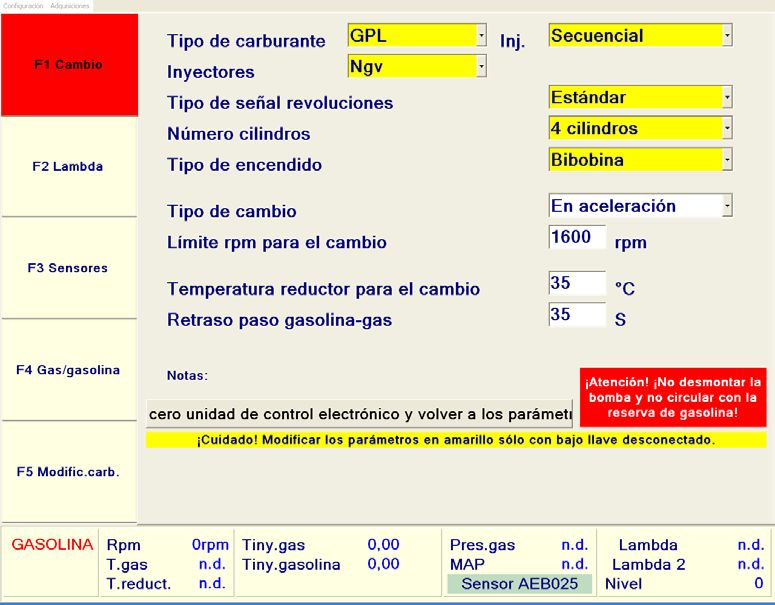
INDICE
ITALIANO
Descrizione Generale............................................................................................................3
Avvertenze................................................................................................................................4
Contenuto Della Confezione..............................................................................................4
Collegamento Uscita Segnale Giri....................................................................................5
Aggiornamento Firmware Con Kit Aeb011/Aeb011usb..........................................6
Aggiornamento Firmware Con Kit Aeb011n . .............................................................7
Installazione Sensore Pms Ad Effetto Hall E 1 Sensore Di Fase Hall.....................8
Programmazione....................................................................................................................9
Emergenza............................................................................................................................. 12
Garanzia.................................................................................................................................. 14
Dati Tecnici............................................................................................................................. 15
Omologazioni....................................................................................................................... 43
DESCRIZIONE GENERALE
Variatore elettronico d'anticipo installabile su vetture dotate di sensore di PMS
effetto Hall. E' in grado di regolare in maniera del tutto automatica l'anticipo, di
migliorare le prestazioni e i consumi.

•     Firmware e Hardware di nuova concezione in grado di allargare il ran-
      ge di utilizzo del variatore su nuovi modelli di autovetture come Honda
      Civic 1.8, ecc...
•     Uscita ottimizzata per la lettura dei giri utilizzabile collegando al variato-
      re centraline Iniezione e Feed-back.
•     Massima compatibilità con il cablaggio della precedente versione 511N
      nonostante la differente dimensione del connettore (vedere figura sot-
      tostante).

                                                    CONNETTORE VARIATORE

                                                         CONNETTORE CAVO
                                                             KF511/2

POSIZIONARE IL CONNETTORE DEL CAVO KF511/2 ALL’ESTREMA DESTRA
DEL CONNETTORE DEL VARIATORE 518N.
                                                                                       ITALIANO

                                                                                  3
AVVERTENZE

                        - Installare in posizione verticale lontano da possibili infiltrazioni
                        d'acqua.

                        - Installare lontano da eccessive fonti di calore (es. collettori di
                        scarico).

                        - Installare lontano dalla bobina d'accensione e passare il
                        cablaggio lontano dai cavi dell'alta tensione.

                        - Realizzare delle buone connessioni elettriche evitando l'uso dei
                 OK
                        “rubacorrente”. Si tenga presente che la migliore connessione è la
                        saldatura debitamente isolata.

                        - Non aprire per nessun motivo la scatola del Variatore, soprattutto
                        con il motore in moto o il quadro inserito.
                        L'A.E.B. declina ogni responsabilità per danni a cose e persone
                        derivati dalla manomissione del propio dispositivo da parte
                        di personale non autorizzato.

                      CONTENUTO DELLA CONFEZIONE
           All’interno della confezione è presente:

           1) N°1 Scatola d’imballo
           2) N°1 Istruzione di montaggio
           3) N°1 Centralina
ITALIANO

           4) N°1 Cablaggio di collegamento
           5) N°1 Connettore emergenza
           6) N°1 Sacchetto accessori
           7) N°1 Etichetta attenzione

           4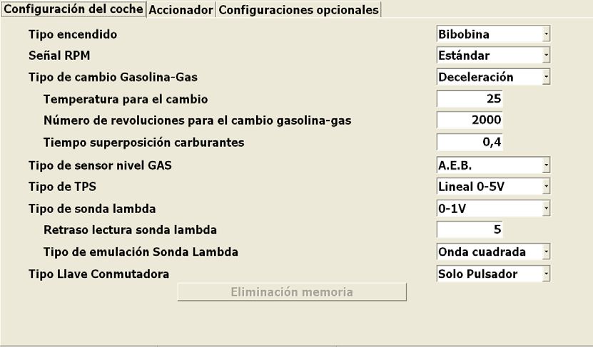
COLLEGAMENTO USCITA SEGNALE GIRI
Sul cablaggio del variatore AEB518N è stata predisposta un'uscita segnale giri
(filo marrone) che può essere utilizzata dai sistemi ad Iniezione o Feed-back
come riferimento giri motore.
ATTENZIONE: Se si collega l’uscita segnale giri (filo marrone) ad un feed-
back o ad un’iniezione, settare (tramite apposito software da PC) i para-
metri come visualizzato di seguito.
                            SISTEMI FEED-BACK

                                 IMPOSTARE
                        Tipo di accensione: Bibobina
                        Tipo di segnale giri: Standard

                            SISTEMI INIEZIONE

                            IMPOSTARE
                   Tipo di accensione: Bibobina
                   Tipo di segnale giri: Standard
                                                                                 ITALIANO

                                                                            5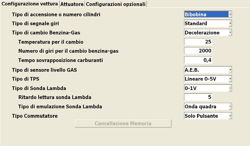
AGGIORNAMENTO FIRMWARE CON KIT AEB011/AEB011USB

                                                                                                              4            5
                                   COMPUTER CLIENTE
                                                                                                           CHIAVE  CHIAVE
                                CON INSTALLATO APPOSITO
                                                                                                          HARDWARE  USB
                                     SOFTWARE PER
                                                                 Italiano
                                                                 English
                                   PROGRAMMAZIONE                Français
                                                                 Polski
                                                                 Português
                                                                 Español
                              VARIATORI ED EMULATORI OBD            OBD Emulators & T.A.P.
I                                                                   Programming Software
                               (VERSIONE 3.3 O SUPERIORE)
T                                                                            6
A                                                                                                       COLLEGARE ALLA
                                                         COLLEGARE ALLA PRESA                           PORTA PARALLELA
L                                                        SERIALE DEL COMPUTER                           (LPT1) O USB DEL
                                                                                                           COMPUTER
                1 2
           ON

I
                                                                                                     COMPOSIZIONE KIT AEB011
A                                                                                                1   CAVO DI CONNESSIONE AL PC
                                                         PRESA                                   2
                           COLLEGARE IL CAVO DEL KIT DI                                              ALIMENTATORE DI RETE
N                                                       220 V A.C.                               3
                              RIPROGRAMMAZIONE                                                       INTERFACCIA SERIALE
                         1    ALL’ESTREMA DESTRA                                                 4   CHIAVE PARALLELA
O                          DEL CONNETTORE VARIATORE                                              6   CD INSTALLAZIONE SOFTWARE
                                                          2
                                                                                                     COMPOSIZIONE KIT AEB011 USB
                                                                                                 1   CAVO DI CONNESSIONE AL PC
                                                                ALIMENTATORE                 3   2   ALIMENTATORE DI RETE
                                               INTERFACCIA                                       3   INTERFACCIA SERIALE
                                                 SERIALE                                         5   CHIAVE USB
    N.B: Nel caso in cui il PC sia sprovvisto di porta seriale, è disponibile l’adapter          6   CD INSTALLAZIONE SOFTWARE
    seriale/usb codice AEB020 US-SE

6
AGGIORNAMENTO FIRMWARE CON KIT AEB011N

                                          CD INSTALLAZIONE                          CHIAVE
                                              SOFTWARE                               USB
                                                                                                                COMPUTER CLIENTE
                                                                                                             CON INSTALLATO APPOSITO
                                                Italiano
                                                                                                                  SOFTWARE PER
                                                English
                                                Français
                                                Polski                                                          PROGRAMMAZIONE
                                                Português
                                                Español

                                                   OBD Emulators & T.A.P.                                  VARIATORI ED EMULATORI OBD
                                                   Programming Software

I                                                                                                           (VERSIONE 3.3 O SUPERIORE)
                                                            3                         4
T
A                                                                                                                COLLEGARE ALLA
                                                                            COLLEGARE ALLA PRESA
                                                                                                                  PORTA USB DEL
                                                                            SERIALE DEL COMPUTER
L              1 2
                                                                                                                    COMPUTER
          ON

I
                             1   COLLEGARE IL CAVO
                                                                            PRESA
A                                DI CONNESSIONE PC   220 V A.C.                                            COMPOSIZIONE KIT AEB011N
N                               ALL’ESTREMA DESTRA                                                     1   CAVO DI CONNESSIONE AL PC
                             DEL CONNETTORE VARIATORE                                                  2   ALIMENTATORE DI RETE
                     1234

O                                                                                                      3   CD INSTALLAZIONE SOFTWARE
                                                                                      2                4   CHIAVE USB

                                                                                ALIMENTATORE   5         INTERFACCE
                                                                                                         (NON COMPRESE NEL KIT)
                                                                                                       5 INTERFACCIA SERIALE (AEB001NG)
                                                                                                       6 INTERFACCIA USB (AEB001N USB)
                                                                                                   6

    N.B: Per la connessione del variatore al PC, non sono necessari entrambi i cavi (N°5 e N°6) in figura, ma solamente
    uno dei due.
7
INSTALLAZIONE SENSORE PMS AD EFFETTO HALL E 1 SENSORE DI
FASE HALL
OPTIONAL
FILO SEGNALE
CONNETTORE
DEL SENSORE AL CONNETTORE
ALBERO A CAM DEL SENSORE DI PUNTO MORTO
(EFFETTO HALL) SUPERIORE
DA COLLEGARE SOLO (EFFETTO HALL)
I
SU ALCUNE VETTURE
T
A
L ROSA
(INGRESSO SEGNALE)
I
VERDE *
A ROSA-NERO
(USCITA SEGNALE)
N VERDE-NERO *
O
NERO BLU ROSSO
USCITA BLU-GIALLO
SEGNALE GIRI MARRONE
PER FEEDBACK O
INIEZIONE POTENZIOMETRO
FARFALLA MASSA +12 VOLT
* SE NON COLLEGATO ISOLARE SOTTOCHIAVE
FILO
SEGNALE POSIZIONE GAS
8 DEL COMMUTATOREPROGRAMMAZIONE
Il Variatore PANDA è riprogrammabile, quindi un solo modello di Variatore si
potrà adattare a diversi modelli di vetture, aggiornando semplicemente il Fir-
mware al suo interno, tramite un qualsiasi kit di programmazione:
• AEB011 (con chiave hardware)
• AEB011USB (con chiave usb)
• AEB011 N.
Si tenga presente che, in fase di collaudo, il Variatore è programmato con il
Firmware per Honda Civic 1.8, quindi verificare sempre se questo è adatto alla
vettura su cui dovrà essere installato.
Il Variatore PANDA Codice AEB518N, amplia la gamma di utilizzo del proceden-
te modello AEB511N con la possibilità di essere installato su nuovi modelli di
autovetture testati da A.E.B, quali:
Cod. Tipo
Vettura C.C. Anno
Motore Centralina
Chrysler Gran
3.3i 2003
Voyager
Bosch
Skoda
1.6i 2008 Motronic
Roomster
ME7.5.20
Siemens
Dodge Caliber 1.8i 2008 P
VDO
Bosch
Honda Civic 1.8i 2008 R18A2
ME763.A0
Gli schemi elettrici d’installazione di ogni singola vettura invece, saranno di-
sponibili nel programma AEB On-Line; per chi ne fosse sprovvisto si dovrà ri-
volgere al suo rivenditore di fiducia o al nostro servizio di assistenza tecnica.
ITALIANO
9PROGRAMMAZIONE
REGOLAZIONE DELL’ ANTICIPO
Parte inferiore del variatore
REGISTRO INTERVENTO ANTICIPO
1 2
ON
LED ACCESO = ANTICIPO INSERITO
CONNETTORE PER IL COLLEGAMENTO E RIPROGRAMMAZIONE
MICROINTERRUTTORI PER LA PROGRAMMAZIONE
PROGRAMMAZIONE GRADI DI ANTICIPO
15° di anticipo 12° di anticipo
9° di anticipo 6° di anticipo
ITALIANO
10PROGRAMMAZIONE
Come e quando disinserire l’anticipo in decelerazione e al minimo
Su alcune vetture è conveniente togliere l’anticipo in decelerazione e al mini-
mo, per evitare saltellii o funzionamenti irregolari.
D’altra parte l’anticipo serve immediatamente in fase di accelerazione, per mi-
gliorare prestazioni, consumi e ridurre al minimo il pericolo di ritorni di fiam-
ma. Con il Variatore PANDA l’anticipo si può inserire o disinserire automatica-
mente collegando il filo BLU-GIALLO del Variatore al potenziometro farfalla.
NOTA: tralasciare l’operazione taratura inserimento anticipo nel caso non si
colleghi il filo BLU-GIALLO.
TARATURA INSERIMENTO ANTICIPO
TPS COLLEGATO:
Il segnale del potenziometro farfalla non è sempre uguale pertanto è prevista
una taratura del punto d’intervento.
La regolazione si effettua durante il funzionamento a GAS agendo sul registro
intervento anticipo nel seguente modo:
1) Verificare che il registro sia ruotato tutto in senso orario.
2) Con la vettura al minimo iniziare a ruotare il registro in senso antiorario fin-
chè non si spegne il led ROSSO (anticipo disinserito).
REGISTRO INTERVENTO ANTICIPO
3) Così regolato, accelerando, il led ROSSO sul Variatore si riaccende per poi
spegnersi quando si rilascia l’acceleratore.
LED ACCESO = ANTICIPO INSERITO
TPS SCOLLEGATO:
É possibile escludere l’intervento dell’anticipo ruotando completamente il
registro in senso antiorario; il variatore inizia ad anticipare solo al superamen-
to di una soglia di giri predefinita (1250 RPM).
ITALIANO
11EMERGENZA
Avvisare il cliente che in caso di avaria il Variatore è dotato di con-
nettore di emergenza che lo esclude e ripristina il collegamento
originale.
PER ESCLUDERLO OPERARE COME SEGUE
FUNZIONAMENTO NORMALE
La spina del cablaggio è inserita nel
ON
1 2 connettore del Variatore.
FUNZIONE EMERGENZA
Togliere il cablaggio dal connettore del
ON
1 2
variatore ed inserirlo nel connettore di
EMERGENZA come da schema.
ITALIANO
12CONTRATTO DI LICENZA D’USO
Leggere con attenzione le seguenti condizioni generali.
Si precisa che le seguenti condizioni si intendono integralmente conosciute ed accettate al momen-
to dell’utilizzo del prodotto.
Oggetto del contratto
A.E.B. s.r.l. conserva la proprietà sul software (d’ora d’innanzi denominato “PROGRAMMA”) contenu-
to all’interno del prodotto A.E.B. da Voi acquistato.
Con la vendita del prodotto A.E.B. s.r.l. non cede alcun diritto sul PROGRAMMA ,ma solo la facoltà di
utilizzo quale utente finale dello stesso, secondo le modalità di cui alle presenti condizioni generali
e secondo le ulteriori condizioni e avvertenze presenti nel manuale d’uso.
A.E.B. s.r.l. è la sola titolare dei diritti di privativa sul PROGRAMMA, dei diritti morali e di utilizzazione
economica, ivi compresi il diritto di riproduzione, traduzione, adattamento, trasformazione, modi-
ficazione e distribuzione, sotto qualsiasi forma e senza limitazione alcuna, compresa la vendita e la
locazione anche di sue copie e delle sue versioni modificate od aggiornate.
A.E.B. s.r.l. è, altresì, titolare del diritto di proprietà su tutti i codici oggetto e su tutti i codici sorgente
del PROGRAMMA.
Tutte le tecniche, gli algoritmi e i procedimenti contenuti nel Programma e nella relativa documen-
tazione sono informazioni riservate di proprietà di A.E.B. s.r.l..
Il Licenziatario non potrà in alcun modo disporre dei codici oggetto e di codici sorgente, né farne og-
getto di licenza o consentirne l’elaborazione, o impegnarne od altrimenti trasferire o in qualsivoglia
altro modo rendere disponibile a terzi il PROGRAMMA sia a titolo oneroso che gratuito.
Il Licenziatario non potrà concedere in locazione o in leasing il PROGRAMMA o parte di esso.
Utilizzo del PROGRAMMA
Il Licenziatario non potrà riprodurre, tradurre, adattare, trasformare, modificare il PROGRAMMA o
qualsiasi parte in esso contenuta, né potrà incaricare terzi di eseguire tali attività.
Il Licenziatario non potrà copiare, nemmeno parzialmente, i manuali relativi al PROGRAMMA e
l’eventuale materiale aggiuntivo (diagrammi logici o di flusso, ecc.) e non potrà consentirne l’uso
a terzi.
Il Licenziatario non potrà decodificare, decompilare, disassemblare, modificare o tradurre il PRO-
GRAMMA, salvo quanto espressamente previsto da norme inderogabili di legge.
Il PROGRAMMA è concesso in licenza d’uso quale prodotto unitario.
Le sue singole parti componenti non possono essere separate per l’utilizzo in ambienti di elabora-
zione distinti o da parte di soggetti diversi dal Licenziatario.
In nessun caso A.E.B. srl sarà ritenuto responsabile dei danni diretti ed indiretti (inclusi il danno per
perdita o mancato guadagno o risparmio, o interruzione dell’attività, perdita di informazioni o dati)
derivante da una non corretta installazione del software o da un suo utilizzo non conforme alle
indicazioni riportate nel manuale d’istruzione.
Dal momento di interruzione della licenza o dallo scioglimento, per qualsiasi ragione verificatosi, del
presente contratto, rimane fermo il divieto d’uso, duplicazione o manipolazione del PROGRAMMA; il
Licenziatario sarà altresì tenuto ad osservare l’obbligo di confidenzialità per 5 anni dalla cessazione
del presente contratto.
Marchio
Tutti i marchi registrati e non, come ogni segno distintivo o denominazione, apposto sul PROGRAM-
MA e sulla relativa documentazione, restano di proprietà di A.E.B. s.r.l. senza che dalla stipulazione
del presente contratto derivi al Licenziatario alcun diritto sui medesimi.
Terzi, collaboratori e dipendenti del Licenziatario
Il Licenziatario si obbliga a far sì che quanti (dipendenti, collaboratori, clienti, fornitori, agenti) hanno
accesso al PROGRAMMA si vincolino al rispetto di tutti gli impegni qui assunti dallo stesso Licen-
ziatario.
Resta inteso che il Licenziatario rimane responsabile per qualsiasi inadempimento ascrivibile a colo-
ro che hanno avuto accesso al PROGRAMMA.
Foro competente
Foro competente a conoscere delle controversie relative all’interpretazione ed applicazione del pre-
sente contratto è il foro di Reggio Emilia.
Legge applicabile
ITALIANO
La legge applicabile al presente contratto è la legge italiana.
Per quanto non espressamente disciplinato troveranno applicazione le norme del codice civile ita-
liano.
La nullità di una o più condizioni contenute nella presente licenza d’uso non comporterà in principio
la nullità dell’intero contratto.
13GARANZIA
Gentile Cliente,
grazie per la fiducia accordata all’A.E.B. acquistando questo prodotto.
L’A.E.B. sottopone tutti i suoi prodotti a severi test di qualità; se nonostante
i controlli il prodotto dovesse presentare dei malfunzionamenti, Le
raccomandiamo di rivolgersi subito all’installatore per i controlli o gli interventi
del caso.
- Norme generali di garanzia
A.E.B. garantisce il buon funzionamento di questo prodotto e la sua immunità
da vizi e difetti costruttivi.
Se durante il periodo di garanzia il prodotto risultasse difettoso, A.E.B. si
farà carico delle riparazioni o sostituzioni del caso, affidandone l’esecuzione
preferibilmente all’originario installatore, altrimenti a chi designato di comune
accordo.
Le sostituzioni dei pezzi difettosi avverranno franco stabilimento A.E.B. e con
spese di spedizione a carico del destinatario.
Per gli accessori od i componenti non costruiti da A.E.B. valgono soltanto le
garanzie riconosciute dai terzi produttori.
La presente garanzia è l’unica prestata da A.E.B., restandone pertanto esclusa
ogni altra.
Nessuna responsabilità, se non in caso di dolo o colpa grave, potrà far carico
ad A.E.B. per danni a persone o cose a chiunque derivati da malfunzionamenti
del prodotto.
La presente garanzia è operativa soltanto per chi è in regola con i pagamenti.
- Condizioni
La garanzia verrà riconosciuta per un periodo di 24 mesi dalla data stampata
sul prodotto con vernice indelebile.
La garanzia varrà soltanto se al momento dell’acquisto il prodotto risulta ben
conservato ed integro nel suo imballaggio e confezionamento predisposti
da A.E.B., che sono gli unici ad assicurarne provenienza ed un’adeguata
protezione.
- Esclusioni della garanzia
Questa garanzia non copre:
a) Controlli periodici, manutenzioni, riparazioni o sostituzione di pezzi dovuti
al normale deterioramento.
b) Malfunzionamenti dovuti a incuria, cattiva installazione, uso improprio
o non conforme alle istruzioni tecniche impartite ed in genere ogni
malfunzionamento non riconducibile a vizi e difetti costruttivi del prodotto e
dunque a responsabilità di A.E.B..
c) Prodotti da chiunque modificati, riparati, sostituiti, montati e comunque
manomessi senza la preventiva autorizzazione scritta di A.E.B..
d) Incidenti, originati da cause di forza maggiore od altre cause (ad es. acqua,
fuoco, fulmine, cattiva aereazione, ecc.) non dipendenti dalla volontà di A.E.B..
ITALIANO
Chiunque dovrà astenersi dal rivendere od installare prodotti affetti da vizi o
difetti costruttivi riconoscibili con la normale diligenza.
Il Foro competente per eventuali controversie in ordine all’interpretazione ed
esecuzione di questa garanzia è unicamente quello di Reggio Emilia.
14DATI TECNICI
Tensione di alimentazione 10 ÷ 14 Vcc
Regolazione anticipo 6°-9°-12°-15°
Altezza 105 mm
Profondità 35 mm
Ingombri scatola variatore
larghezza 80 mm
Ø foro di fissaggio 6 mm
Anticipo disinseribile in decelerazione tramite segnale T.P.S.
Programmazione di diversi tipi di ruota fonica in modo da poter
essere adattato a numerosi modelli di vetture.
Possibilità di collegamento all'uscita giri di una centralina feed-back
o iniezione.
ITALIANO
15INDEX
ENGLISH
General Description............................................................................................................ 17
Warnings................................................................................................................................. 18
Contents Of The Package................................................................................................. 18
Revolution Signal Output Connection........................................................................ 19
Firmware Update With Aeb011/Aeb011usb Kit....................................................... 20
Firmware Update With Aeb011n Kit............................................................................. 21
Installation Of Hall Effect Pms Sensor And 1 Hall Phase Sensors....................... 22
Programming........................................................................................................................ 23
Emergency............................................................................................................................. 26
User Licence Agreement................................................................................................... 27
Warranty................................................................................................................................. 28
Technical Data...................................................................................................................... 29
Type Approvals..................................................................................................................... 43
ENGLISH
16GENERAL DESCRIPTION
Electronic timing advance processor installable in vehicles equipped with an
Hall effect TDC sensor. Able to automatically adjust the advance, improve per-
formance and consumption.
• New concept Firmware and Hardware able to broaden the range of use
of the timing advance processor on new vehicle models such as Honda
Civic 1.8, etc.
• Optimised output for reading the revolutions, can be used by connect-
ing the Injection and Feedback control units to the timing advance
processor.
• Maximum compatibility with the wiring harness of the former 511N ver-
sion in spite of the different connector size (see the figure below).
TIMING ADVANCE
CONNECTOR
KF511/2
CABLE CONNECTOR
SET THE KF511/2 CABLE CONNECTOR TO THE FAR RIGHT OF THE 518N
TIMING ADVANCE PROCESSOR CONNECTOR.
ENGLISH
17WARNINGS
- Install vertically away from possible water leaks.
- Install away from excessive heat sources (e.g. exhaust mani-
folds).
- Install away from the ignition coils and route the wiring harness
away from high voltage wires.
- Make good electrical connections without using cable clamps.
OK
Remember that the best connection is a duly insulated soldering.
- Do not open the timing advance processor casing for any rea-
son whatsoever, especially when the engine is running or the
panel is switched on.
A.E.B. shall not be held liable for damage to things or peo-
ple caused by unauthorised personnel tampering with the
device.
CONTENTS OF THE PACKAGE
The package contains:
1) No.1 Packaging box
2) No.1 Assembly instruction manual
3) No.1 Control unit
ENGLISH
4) No.1 Connection wiring harness
5) No.1 Emergency connector
6) No.1 Bag of accessories
7) No.1 Warning label
18REVOLUTION SIGNAL OUTPUT CONNECTION
The wiring harness of the AEB518N timing advance processor features a revo-
lution signal output (brown wire) that can be used by injection or feedback
systems as an engine revolutions reference.
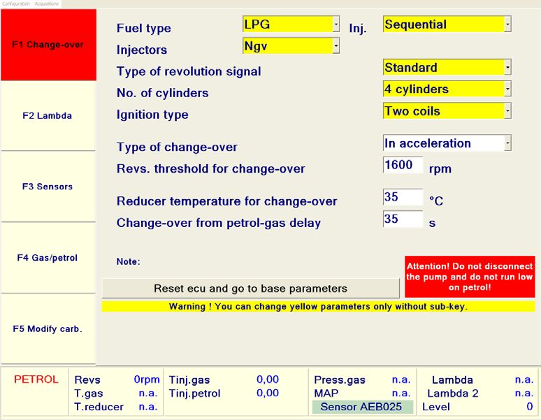
CAUTION: If the revolution signal output (brown wire) is connected to a
feedback or injection control unit, set the parameters as displayed below
(using a PC and the software).
FEEDBACK SYSTEMS
SET:
Ignition type: Dual coil
Type of RPM signal: Standard
INJECTION SYSTEMS
SET:
Type of revolution signal: Standard
Ignition type: Dual coil
ENGLISH
19FIRMWARE UPDATE WITH AEB011/AEB011USB KIT
4 5
CLIENT COMPUTER WITH
HARDWARE
SPECIFIC SOFTWARE INSTALLED USB KEY
KEY
FOR PROGRAMMING TIMING
Italiano
English
ADVANCE PROCESSORS AND Français
Polski
Português
Español
OBD EMULATORS OBD Emulators & T.A.P.
Programming Software
E (VERSION 3.3 OR LATER).
6
N CONNECT
G CONNECT TO THE TO THE COMPUTER
COMPUTER SERIAL PORT PARALLEL PORT (LPT1)
L OR USB PORT.
1 2
ON
I COMPOSITION OF THE AEB011 KIT
220 V.A.C. 1 PC CONNECTION CABLE
S CONNECT THE CABLE OF POWER 2 MAINS POWER SUPPLY
THE REPROGRAMMING KIT 3 SERIAL INTERFACE
H 1 TO THE FAR RIGHT OF THE OUTLET.
4 PARALLEL KEY
TIMING ADVANCE PROCESSOR
CONNECTOR 6 SOFTWARE INSTALLATION CD
2
COMPOSITION OF THE AEB011 USB KIT
1 PC CONNECTION CABLE
POWER SUPPLY 3 2 MAINS POWER SUPPLY
SERIAL 3 SERIAL INTERFACE
INTERFACE 5 USB KEY
NOTE: If the PC does not have a serial port, a serial/USB adapter is available 6 SOFTWARE INSTALLATION CD
(code AEB020 US-SE).
20FIRMWARE UPDATE WITH AEB011N KIT
SOFTWARE USB KEY
INSTALLATION CD CCLIENT COMPUTER
WITH SPECIFIC SOFTWARE
INSTALLED FOR
Italiano
English PROGRAMMING TIMING
Français
Polski
Português
Español
ADVANCE PROCESSORS AND
OBD Emulators & T.A.P.
Programming Software
OBD EMULATORS
E 3 4 (VERSION 3.3 OR LATER).
N CONNECT TO THE
CONNECT TO THE
G COMPUTER USB
COMPUTER SERIAL PORT
1 2
PORT
ON
L
I 220 V.A.C.
1 CONNECT THE PC COMPOSITION OF THE
POWER
S CONNECTION CABLE TO AEB011N KIT
THE FAR RIGHT OF THE OUTLET 1
TIMING ADVANCE
PC CONNECTION CABLE
2
1234
H PROCESSOR CONNECTOR MAINS POWER SUPPLY
3
SOFTWARE INSTALLATION CD
2 4
USB KEY
POWER SUPPLY 5
INTERFACES
(NOT INCLUDED IN THE KIT)
5
SERIAL INTERFACE (AEB001NG)
6
6 USB INTERFACE (AEB001N USB)
NOTE: To connect the timing advance processor to the PC, it is not necessary to use both the cables (NO.5 and NO.6)
illustrated in the figure, just one is enough.
21INSTALLATION OF HALL EFFECT PMS SENSOR AND 1 HALL
PHASE SENSORS
OPTIONAL
CAM SHAFT SENSOR
CONNECTOR SIGNAL
WIRE TO THE TOP DEAD CENTRE SENSOR
(HALL EFFECT) CONNECTOR
ONLY TO BE (HALL EFFECT)
CONNECTED ON
E SOME VEHICLES
N
G PINK
L (SIGNAL INPUT)
I GREEN *
PINK-BLACK
S (SIGNAL OUTPUT)
H GREEN-BLACK *
BLACK BLUE RED
REVOLUTION BLUE-YELLOW
SIGNAL OUTPUT BROWN
FOR FEEDBACK
OR INJECTION THROTTLE
POTENTIOMETER GROUND +12 VOLT
* ISOLATE IF NOT CONNECTED SUBKEY
SIGNAL
WIRE SWITCH SET ON GAS
22PROGRAMMING
The PANDA timing advance processor is reprogrammable; therefore, just one
timing advance processor model can be adapted to various vehicle models by
simply updating the Firmware using any programming kit.
• AEB011 (with hardware key)
• AEB011USB (with USB key)
• AEB011 N
Bear in mind that during the test phase, the timing advance processor is pro-
grammed with the Firmware for Honda Civic 1.8, therefore always ensure that
this is suitable for the vehicle on which it has to be installed.
The PANDA timing advance processor code AEB518N, broadens the range of
use of the former AEB511N model with the possibility of being installed on
new vehicle models tested by A.E.B., such as:
Engine Type of
Vehicle C.C. Year
Code Control Unit
Chrysler Gran
3.3i 2003
Voyager
Skoda Bosch Motronic
1.6i 2008
Roomster ME7.5.20
Dodge Caliber 1.8i 2008 P Siemens VDO
Honda Civic 1.8i 2008 R18A2 Bosch ME763.A0 ENGLISH
The installation wiring diagrams of each vehicle will be available in the A.E.B.
On-Line program; if you do not have the A.E.B. On-Line program, please con-
sult your dealer or our technical assistance service.
23PROGRAMMING
TIMING ADVANCE ADJUSTMENT
Lower part of the timing advance processor
TIMING ADVANCE TRIP REGISTER
1 2
ON
LED ON = TIMING ADVANCE ENABLED
CONNECTION AND REPROGRAMMING CONNECTOR
PROGRAMMING MICROSWITCHES
TIMING ADVANCE DEGREES PROGRAMMING
15° advance 12° advance
9° advance 6° advance
ENGLISH
24PROGRAMMING
How and when to disable the timing advance during deceleration and
when idling
On some vehicles it is convenient to disable the timing advance during decel-
eration and when idling to avoid jumps or irregular function.
On the other hand, the timing advance is required immediately during ac-
celeration to improve performance, consumption and to minimise the risk of
backfiring. With the PANDA timing advance processor, the timing advance can
be enabled or disabled automatically connecting the BLUE-YELLOW wire on
the timing advance processor to the throttle potentiometer.
NOTE: do not carry out the timing advance enabling calibration procedure if
the BLUE-YELLOW wire is not connected.
TIMING ADVANCE ENABLING CALIBRATION PROCEDURE
TPS CONNECTED:
the throttle potentiometer signal is not always the same; therefore, the trip
point needs to be calibrated.
Adjustment is carried out during GAS function by acting on the timing ad-
vance trip register as follows:
1) Ensure the register is turned completely clockwise.
2) While the vehicle is idling, turn the register anticlockwise until the RED LED
switches off (timing advance disabled).
TIMING ADVANCE TRIP REGISTER
3) With this adjustment, during acceleration, the RED LED on the timing advance
processor lights up and then switches off when the accelerator is released.
LED ON = TIMING ADVANCE ENABLED
TPS DISCONNECTED:
It is possible to cut off the timing advance by turning the register completely
anticlockwise; the timing advance processor starts to advance only when a
preset threshold is exceeded (1250 rpm).
ENGLISH
25EMERGENCY
Warn the customer that in case of a malfunction, the timing ad-
vance processor is equipped with an emergency connector that
cuts it off and restores the original connection.
TO CUT OFF, PROCEED AS FOLLOWS
NORMAL FUNCTION
The wiring harness outlet is inserted
ON
1 2 in the timing advance processor con-
nector.
EMERGENCY FUNCTION
ON
1 2
Remove the wiring harness from the
timing advance connector and insert
it in the EMERGENCY connector as
indicated in the diagram.
ENGLISH
26USER LICENCE AGREEMENT
Read the following general conditions carefully.
The user shall be deemed to be fully acquainted with the following conditions and to have accepted
them at the time of the software usage.
Scope of the agreement
A.E.B. s.r.l. retains ownership of the software (herein referred to as “PROGRAM”) required to use the A.E.B. pro-
duct you have purchased.
A.E.B. s.r.l. does not assign any rights to the PROGRAM through the sale of this product, but solely the right of
use as the end user of the said product, in accordance with the modalities described in these general condi-
tions and subject to further conditions and cautions given in the user manual.
A.E.B. s.r.l. is the sole holder of all copyright and other rights of the PROGRAM, the moral rights and the rights
of economic use, including the right of reproduction, translation, adaptation, transformation, modification
and distribution, in any form and with no restrictions whatsoever, including the sale and the lease of its copies
and of modified or updated versions.
A.E.B. s.r.l. is also the holder of the intellectual property rights to all the object codes and to all the source
codes for the PROGRAM.
All the techniques, algorithms and procedures contained in the PROGRAM and in the associated documenta-
tion are considered confidential and property of A.E.B. s.r.l.
The Licensee may not dispose in any way of the object codes or source codes, or include them as part of a
licence, or allow them to be processed, pledged or otherwise transferred, or in any way to make the PROGRAM
available to third parties whether for sale or for free.
The Licensee shall not hire or lease the PROGRAM or any part of it.
Use of the PROGRAM
The Licensee may not reproduce, translate, adapt, transform, modify the PROGRAM or any part of its contents,
nor may it engage third parties to perform the said activities.
The Licensee may not copy, even in part, the manuals relating to the PROGRAM and any additional material
(logical diagrams or flow charts, etc.) and may not consent to their use by third parties.
The Licensee may not decodify, decompile, disassemble, modify or translate the PROGRAM, except as expres-
sly provided under mandatory statutory regulations.
This user licence is granted for the PROGRAM as a single product.
Its individual component parts may not be divided for use in separate processing environments or by parties
other than the Licensee.
Under no circumstances shall A.E.B. s.r.l. be liable for direct and indirect damage (including damage throu-
gh loss of earnings or savings, or interruptions to activities, loss of information or data) deriving from the
incorrect installation of the software or from any use that does not comply with the indications given in the
user manual.
Any interruption to the licence or the cancellation of this agreement, for whatever reason this occurs, shall not
detract from the prohibition to use, duplicate or tamper with the PROGRAM; the Licensee will also undertake
to observe the obligation of confidentiality for 5 years after the date when this agreement expires.
Trademark
All trademarks, whether registered or not, and all distinctive signs or names used to mark the PROGRAM and
the associated documentation shall remain the property of A.E.B. s.r.l. and the Licensee shall derive no rights
to the latter by entering into this agreement.
Third parties and the Licensee’s collaborators and employees
The Licensee undertakes to ensure that all persons (employees, collaborators, clients, suppliers, agents) with
access to the PROGRAM are bound to observe all the obligations assumed herein by the Licensee.
It is hereby understood that the Licensee will be liable for any breach attributable to those individuals who
have been given access to the PROGRAM.
Court with jurisdiction
The court with jurisdiction to settle any disputes concerning the construal and application of this agreement
will be the Court of Reggio Emilia.
Applicable law
ENGLISH
This contract will be governed by Italian law.
In the event of any aspect not expressly provided for herein, reference will be made to the provisions of the
Italian Civil Code.
The nullity of one or more conditions of this user license will not, in principle, determine the nullity of the
entire agreement.
27WARRANTY
Dear Customer,
Thank you for the trust you have placed in A.E.B. by purchasing this product.
A.E.B. subjects all its products to severe quality tests. If, in spite of the controls,
the product should malfunction, we recommend you immediately contact the
installer for any checks or interventions necessary.
- General warranty regulations
A.E.B. guarantees that this product operates properly and that it is free of
manufacturing faults and defects.
If the product becomes defective during the warranty period, A.E.B. will
repair or replace it, preferably entrusting the task to the original installer or to
someone else as agreed by the parties.
Defective parts will be replaced ex-works and the recipient shall be responsible
for shipping expenses.
Accessories and components not made by A.E.B. are covered by their
manufacturers’ warranties only.
This is the only warranty offered by A.E.B. All others are excluded.
Unless due to malice or gross negligence, A.E.B. shall not be held liable for any
injury to people or damage to things resulting from product malfunctioning.
This warranty is valid only for those up to date with their payments.
- Conditions
The warranty shall be valid for a period of 24 months starting from the date
printed on the product with indelible ink.
The warranty shall be valid only if, at the time of purchase, the product is
properly stored as in its original A.E.B. packaging. The original packaging is the
only guarantee of origin and adequate protection.
- Warranty exclusions
This warranty does not cover:
a) periodic checks, maintenance, repairs, or replacement of parts due to
normal wear;
b) malfunctioning due to negligence, incorrect installation, improper use or
non-observance of the technical instructions and, in general, any malfunction
not traceable to manufacturing faults or defects of the product and therefore
the responsibility of A.E.B.
c) products modified, repaired, replaced, installed or in any way tampered with
by anyone without the prior written authorization of A.E.B.
d) accidents originating from force majeure or other causes (e.g. water, fire,
lightning, bad ventilation, etc.) not depending on A.E.B.
Products with manufacturing faults or defects recognizable through normal
ENGLISH
diligence must not be resold or installed.
The sole competent court for any disputes concerning the interpretation or
execution of this warranty is that of Reggio Emilia (Italy).
28TECHNICAL DATA
Power supply voltage 10 ÷ 14 Vdc
Timing advance adjustment 6°-9°-12°-15°
Height: 105 mm
Depth: 35 mm
Timing advance processor overall
dimensions
Width: 80 mm
Fixing hole: 6 mm Ø
Timing advance can be disabled during deceleration via TPS signal
Programming of various types of phonic wheel for adaptation to
different vehicle models.
Possibility to connect to revolution output of a feedback or injection
control unit.
ENGLISH
29ÍNDICE
ESPAÑOL
Descripción General........................................................................................................... 31
Advertencias......................................................................................................................... 32
Contenido De La Caja........................................................................................................ 32
Conexión Salida Señal Revoluciones........................................................................... 33
Actualización Firmware Con Kit Aeb011/Aeb011usb............................................ 34
Actualización Firmware Con Kit Aeb011n.................................................................. 35
Instalación Sensor Pms Inductivo Y 2 Sensores De Fase Hall.............................. 36
Programación....................................................................................................................... 37
Emergencia............................................................................................................................ 40
Garantía.................................................................................................................................. 41
Datos Técnicos...................................................................................................................... 42
Homologaciones................................................................................................................. 43
ESPAÑOL
30DESCRIPCIÓN GENERAL
Variador electrónico de avance, instalable en automóviles dotados de sensor
de PMS de efecto Hall. Es capaz de regular, de manera completamente auto-
mática, el avance, de mejorar las prestaciones y los consumos.
• Firmware y Hardware de nueva concepción capaces de ampliar el rango
de uso del variador en nuevos modelos de automóvil como Honda Civic
1.8, etc.
• Salida optimizada para la lectura de las revoluciones utilizable conectan-
do con el variador centralitas de inyección y retroacción.
• Máxima compatibilidad con el cableado de la precedente versión 511N,
no obstante las medidas distintas del conector (véase la figura siguien-
te).
CONECTOR VARIADOR
CONECTOR CABLE KF511/2
SITUAR EL CONECTOR DEL CABLE KF511/2 EN EL EXTREMO DERECHO DEL
CONECTOR DEL VARIADOR 518N.
ESPAÑOL
31ADVERTENCIAS
- Instalar en posición vertical alejado de posibles filtraciones de
agua.
- Instalar alejado de excesivas fuentes de calor (por ej. colectores
de escape).
- Instalar alejado de la bobina de encendido y hacer pasar el ca-
bleado alejado de los cables de la alta tensión.
- Realizar unas buenas conexiones eléctricas evitando el uso de
OK
los “ladrones”. Téngase presente que la mejor conexión es la sol-
dadura debidamente aislada.
- No abrir, por ningún motivo, la caja del variador, sobre todo con
el motor en marcha o con el cuadro encendido.
A.E.B. rehúsa cualquier responsabilidad ante daños a cosas
y personas derivados de la alteración del propio dispositivo
por parte de personal no autorizado.
CONTENIDO DE LA CAJA
Dentro de la caja hay:
1) N°1 Caja de embalaje
2) N°1 Instrucciones de montaje
3) N°1 Centralita
ESPAÑOL
4) N°1 Cableado de conexión
5) N°1 Conector de emergencia
6) N°1 Bolsa de accesorios
7) N°1 Etiqueta de atención
32CONEXIÓN SALIDA SEÑAL REVOLUCIONES
En el cableado del variador AEB518N se ha previsto una salida de señal de revolu-
ciones (cable marrón) que puede ser utilizado por los sistemas de inyección o de
retroacción como referencia de revoluciones del motor.
ATENCIÓN: si se conecta la salida de señal de revoluciones (cable marrón) con
una retroacción o con una inyección, se debe ajustar (por medio del pertinen-
te software desde PC) los parámetros como mostrado a continuación.
SISTEMAS RETROACCIÓN
CONFIGURAR
Tipo encendido: bibobina
Señal RPM: estándar
SISTEMAS INYECCIÓN
CONFIGURAR
Tipo de señal revoluciones: estándar
Tipo de encendido: bibobina
ESPAÑOL
33ACTUALIZACIÓN FIRMWARE CON KIT AEB011/AEB011USB
4 5
ORDENADOR CLIENTE
CON INSTALADO PERTINENTE LLAVE LLAVE
SOFTWARE PARA HARDWARE USB
Italiano
PROGRAMACIÓN DE English
Français
Polski
VARIADORES Y Português
Español
OBD Emulators & T.A.P.
EMULADORES OBD Programming Software
E (VERSIÓN 3.3 O SUPERIOR)
6
S CONECTAR AL
P CONECTAR AL PUERTO PUERTO PARALELO
SERIE DEL ORDENADOR (LPT1) O USB DEL
A ORDENADOR
1 2
ON
Ñ COMPOSICIÓN KIT AEB011
1 CABLE DE CONEXIÓN AL PC
O TOMA 2
CCONECTAR EL CABLE DEL ALIMENTADOR DE RED
220 Vca. 3
KIT DE REPROGRAMACIÓN AL INTERFAZ SERIE
L 1 EXTREMO DERECHO DEL 4 LLAVE PARALELA
CONECTOR VARIADOR 6 CD INSTALACIÓN SOFTWARE
2
COMPOSICIÓN KIT AEB011 USB
1 CABLE DE CONEXIÓN AL PC
ALIMENTADOR 3 2 ALIMENTADOR DE RED
INTERFAZ 3 INTERFAZ SERIE
SERIE 5 LLAVE USB
Nota: En el caso de que el PC no tenga puerto serie, está disponible el 6 CD INSTALACIÓN SOFTWARE
adaptador serie/usb código AEB020 US-SE
34ACTUALIZACIÓN FIRMWARE CON KIT AEB011N
CD INSTALACIÓN LLAVE
SOFTWARE USB ORDENADOR CLIENTE
CON INSTALADO PERTINENTE
SOFTWARE PARA
Italiano
English PROGRAMACIÓN DE
Français
Polski
Português
Español
VARIADORES Y
OBD Emulators & T.A.P.
Programming Software
EMULADORES OBD
E 3 4 (VERSIÓN 3.3 O SUPERIOR)
S CONECTAR AL
CONECTAR AL PUERTO
P PUERTO USB DEL
SERIE DEL ORDENADOR
1 2
ORDENADOR
ON
A
Ñ 1 CONECTAR EL CABLE
TOMA
DE CONEXIÓN PC 220 Vca COMPOSICIÓN KIT AEB011N
O AL EXTREMO DERECHO 1 CABLE DE CONEXIÓN AL PC
DEL CONECTOR VARIADOR 2 ALIMENTADOR DE RED
1234
L
3 CD INSTALACIÓN SOFTWARE
2 4 LLAVE USB
ALIMENTADOR 5 INTERFACES
(NO INCLUIDAS EN EL KIT)
5 INTERFAZ SERIE (AEB001NG)
6 INTERFAZ USB (AEB001N USB)
6
Nota: Para la conexión del variador al PC no se necesitan ambos cables (N°5 y N°6) en la figura, sino tan solo uno de
los dos.
35INSTALACIÓN SENSOR PMS INDUCTIVO Y 2 SENSORES DE FASE HALL
OPCIÓN
CABLE SEÑAL
CONECTOR DEL
SENSOR ÁRBOL DE AL CONECTOR
LEVAS (EFECTO HALL) DEL SENSOR DE
A CONECTAR SÓLO PUNTO MUERTO SUPERIOR
EN ALGUNOS (EFECTO HALL)
E AUTOMÓVILES
S
P ROSA
A (ENTRADA SEÑAL)
Ñ VERDE *
ROSA-NEGRO
O (SALIDA SEÑAL)
L VERDE-NEGRO*
NEGRO AZUL ROJO
SALIDA SEÑAL BLU-GIALLO
REVOLUCIONES MARRÓN
PARA RETROACCIÓN
O INYECCIÓN POTENCIÓMETRO
MARIPOSA MASA +12 VOLTIOS
* SI NO CONECTADO, AISLAR CONTACTO DE
CABLE LLAVE
SEÑAL POSICIÓN GAS
36 DEL CONMUTADORPROGRAMACIÓN
El variador PANDA es reprogramable por lo que un solo modelo de variador se
puede adaptar a distintos modelos de automóvil, simplemente actualizando el
Firmware que lleva utilizando cualquier kit de programación:
• AEB011 (con llave hardware)
• AEB011USB (con llave usb)
• AEB011 N.
Cabe tener presente que, en la fase de ensayo, el Variador está programado
con el Firmware para Honda Civic 1.8, por lo que es necesario comprobar siem-
pre si dicho firmware es idóneo para el automóvil en el cual se va a instalar.
El Variador PANDA código AEB518N, amplía la gama de utilización del modelo
precedente AEB511N con la posibilidad de instalarlo en nuevos modelos de
automóvil ensayados por A.E.B, como por ejemplo:
Cód. Tipo
Automóvil C.C. Año
Motor Centralita
Chrysler Gran
3.3i 2003
Voyager
Bosch
Skoda
1.6i 2008 Motronic
Roomster
ME7.5.20
Siemens
Dodge Caliber 1.8i 2008 P
VDO
Bosch
Honda Civic 1.8i 2008 R18A2
ME763.A0
ESPAÑOL
Los esquemas eléctricos de instalación para cada automóvil estarán, al contra-
rio, disponibles en el programa AEB On-Line; quien no dispusiera de él deberá
acudir a su revendedor de confianza o a nuestro servicio técnico.
37PROGRAMACIÓN
AJUSTE DEL AVANCE
Parte inferior del variador
AJUSTE DE ACTUACIÓN DEL AVANCE
1 2
ON
LED ENCENDIDO = AVANCE ACTIVADO
CONECTOR PARA LA CONEXIÓN Y LA REPROGRAMACIÓN
MICROINTERRUPTORES PARA LA PROGRAMACIÓN
PROGRAMACIÓN GRADOS DE AVANCE
15° de avance 12° de avance
9° de avance 6° de avance
ESPAÑOL
38PROGRAMACIÓN
Cómo y cuándo desactivar el avance en deceleración y al ralentí
En algunos automóviles conviene quitar el avance en deceleración y al ralentí
para evitar saltos o funcionamientos irregulares.
Por otra parte el avance sirve inmediatamente en la fase de aceleración, para
mejorar prestaciones, consumos y reducir al mínimo el peligro de retornos de
llama. Con el variador PANDA el avance se puede activar o desactivar automá-
ticamente conectando el cable AZUL-AMARILLO del variador al potencióme-
tro de mariposa.
NOTA: Si no se conecta el cable AZUL-AMARILLO se puede ignorar la opera-
ción de ajuste de la activación del avance.
AJUSTE DE LA ACTIVACIÓN DEL AVANCE
TPS CONECTADO:
La señal del potenciómetro de mariposa no siempre es igual por lo que está
previsto un ajuste del punto de actuación.
El ajuste se efectúa, durante el funcionamiento con GAS, actuando de la si-
guiente manera sobre el registro de actuación del avance:
1) Comprobar que el registro esté todo girado hacia la derecha (sentido horario).
2) Con el automóvil al ralentí empezar a girar el registro hacia la izquierda (sen-
tido antihorario) hasta que se apaga el LED rojo (avance desactivado).
REGISTRO DE ACTUACIÓN DEL AVANCE
3) Regulado de esta manera, al acelerar el LED rojo en el variador vuelve a en-
cenderse para luego apagarse al soltar el acelerador.
LED ENCENDIDO = AVANCE ACTIVADO
TPS DESCONECTADO:
Es posible excluir la actuación del avance girando completamente hacia la iz-
quierda el registro; el variador activa el avance sólo cuando se supera un um-
bral predeterminado de revoluciones (1250 RPM).
ESPAÑOL
39EMERGENCIA
Avisar al cliente que en caso de avería el variador tiene conector
de emergencia que lo excluye y restablece la conexión original.
PARA EXCLUIRLO ACTUAR COMO SIGUE
FUNCIONAMIENTO NORMAL
La clavija del cableado está enchufada
ON
1 2 en el conector del variador.
FUNCIÓN DE EMERGENCIA
Quitar el cableado del conector del
ON
1 2
variador y enchufarlo en el conector
de EMERGENCIA como mostrado en
el esquema.
ESPAÑOL
40GARANTÍA
Muy amable Cliente,
Las agradecemos la confianza que ha reservado a A.E.B. al comprar este produc-
to.
A.E.B. somete todos sus productos a severas pruebas de calidad; si no obstante
las comprobaciones efectuadas el producto presentara alguna anomalía, las re-
comendamos que acuda enseguida al instalador para que efectúe las comproba-
ciones o las actuaciones necesarias.
- Normas generales de garantía
A.E.B. garantiza el buen funcionamiento de este producto y que está exento de
vicios y de defectos constructivos.
Si durante el periodo de garantía el producto resultara defectuoso, A.E.B. se hará
cargo de las reparaciones o sustituciones necesarias, confiando su realización pre-
ferentemente al instalador original o bien a quien se designe de común acuerdo.
Las sustituciones de las piezas defectuosas serán efectuadas franco fábrica (EXW)
A.E.B. y con gastos de envío a cargo del destinatario.
Para los accesorios o los componentes no fabricados por A.E.B. valen solamente
las garantías reconocidas por los terceros productores.
La presente garantía es la única ofrecida por A.E.B. por lo que queda excluida
cualquier otra.
Ninguna responsabilidad, salvo que en caso de dolo o culpa grave, se podrá car-
gar a A.E.B. por daños a personas o cosas causados a quienquiera por malfuncio-
namientos del producto.
La presente garantía tiene efecto solamente para quien está en regla con los pa-
gos.
- Condiciones
La garantía será reconocida por un periodo de 24 meses desde la fecha impresa
en el producto con tinta indeleble.
La garantía valdrá sólo si en el momento de la compra el producto resulta bien
conservado y está íntegro en su embalaje y caja preparados por A.E.B. que son los
únicos que pueden asegurar su procedencia y adecuada protección.
- Exclusiones de la garantía
a) Comprobaciones periódicas, mantenimientos, reparaciones o sustituciones de
piezas debidos al desgaste normal.
b) Malfuncionamientos debidos a descuido, errónea instalación, uso impropio o
no conforme a las instrucciones técnicas proporcionadas y en general cualquier
mal funcionamiento no atribuible a vicios y defectos de fabricación del producto
y por lo tanto de responsabilidad de A.E.B.
c) Productos modificados, reparados, sustituidos, montados por quienquiera que
sea y de todas maneras alterados sin la previa autorización por escrito de A.E.B.
d) Accidentes debidos a causas de fuerza mayor u otras causas (por ejemplo agua,
fuego, rayos, mala ventilación, etc.) que no dependan de la voluntad de A.E.B.
ESPAÑOL
Todos deberán abstenerse de revender o instalar productos con vicios o defectos
de fabricación reconocibles con la diligencia normal.
El Fuero competente para eventuales controversias relacionadas con la interpre-
tación y la ejecución de esta garantía es únicamente el Fuero de Reggio Emilia.
41DATOS TÉCNICOS
Tensión de alimentación 10 ÷ 14 Vcc
Ajuste de avance 6°-9°-12°-15°
Altura 105 mm
Profundidad 35 mm
Medidas máximas caja variador
Ancho 80 mm
Ø agujero de fijación 6 mm
Avance desactivable en deceleración por medio de señal T.P.S.
Programación de distintos tipos de rueda fónica para poder
adaptarse a numerosos modelos de automóvil.
Posibilidad de conectar a la salida de revoluciones una centralita de
retroacción (feed-back) o inyección.OMOLOGAZIONI/ TYPE APPROVALS
HOMOLOGACIONES
Marchio omologazione Descrizione
Type approval mark Description
Marca homologación Descripción
e3
Direttiva 2006/28/CE .
036264 Directive 2006/28/CE .
Directiva 2006/28/CE .
AEB Alternative Fuel Electronics
via dell’industria 20 42025 - Cavriago - Italy
ph. +39 0522 494401 - fax. +39 0522 494410
www.aeb.it - info@aeb-srl.com
a division of Technical assistance
ph. +39 0522 494414 - fax. +39 0522 494410
aebasst@aeb-srl.comPuoi anche leggere