MANUALE UTENTE - INSTALLATORE PER FILOCOMANDO REMOTO
←
→
Trascrizione del contenuto della pagina
Se il tuo browser non visualizza correttamente la pagina, ti preghiamo di leggere il contenuto della pagina quaggiù
MANUALE UTENTE - INSTALLATORE PER FILOCOMANDO REMOTO                                                                                         IT

               REMOTE WIRE CONTROLLER USER’S – INSTALLER’S MANUAL                                                                                 EN

                                                        MODELLI / MODELS
                                                                     WRC11

  Questo manuale è stato creato per scopo informativo. La ditta declina ogni responsabilità per i risultati di una progettazione o di una installazione
basata sulle spiegazioni e le specifiche tecniche riportate in questo manuale. E’ inoltre vietata la riproduzione anche parziale sotto qualsiasi forma dei
                                                     testi e delle figure contenute in questo manuale.

This manual has been created for informative purposes. The company declines any responsibility for the results of projects or installations based on the
 explanations and the technical specifications provided in this manual. It is besides forbidden the reproduction under any form of the texts and of the
                                                            figures contained in this manual.
ITALIANO
INDICE
PARTE UTENTE ...................................................................................................2
I. PRECAUZIONI DI SICUREZZA ....................................................................................... 2
II. SPECIFICHE TECNICHE ................................................................................................ 2
III. DESCRIZIONE FILOCOMANDO REMOTO ................................................................... 3
IV. ISTRUZIONI DI UTILIZZO .............................................................................................. 3
1. Funzione ricezione segnale remoto ................................................................................... 3
2. Accensione/Spegnimento climatizzatore ........................................................................... 3
3. Impostazione modalità ........................................................................................................ 3
4. Impostazione velocità ventilatore....................................................................................... 3
5. Impostazione temperatura .................................................................................................. 3
6. Impostazione Timer on e Timer off ..................................................................................... 3
7. Impostazione orologio......................................................................................................... 4
8. Blocco filocomando remoto ............................................................................................... 4
9. Funzione promemoria di pulizia del filtro .......................................................................... 4
10. Funzione Swing ................................................................................................................. 4
11. Funzione Follow Me........................................................................................................... 5
V. CERTIFICAZIONE - TECNICA E REQUISITI ................................................................. 5
PARTE INSTALLATORE ......................................................................................6
I. PRECAUZIONI DI SICUREZZA ....................................................................................... 6
II. ACCESSORI DI INSTALLAZIONE .................................................................................. 7
III. PROCEDURA DI INSTALLAZIONE ............................................................................... 8
IV SCHEMA DI CABLAGGIO CON L’UNITÀ INTERNA ..................................................... 9
1PARTE UTENTE
I. PRECAUZIONI DI SICUREZZA
Prima dell’utilizzo del controllo, leggere attentamente le seguenti precauzioni di sicurezza. Osservare le precauzioni di
sicurezza, perché sono molto importanti.
Prima di eseguire un test, è opportuno avere una certa familiarità con gli indicatori e le icone e conformarsi alle
adeguate procedure di sicurezza.
■ Descrizione indicazioni
Simbolo Significato
Avvertimento Indica che un non corretto uso può causare gravi ferite alle persone e rischio di morte.
CAUTELA Indica che un non corretto uso o rispetto delle istruzioni può causare danni a persone e cose.
NOTE:
1. Ferite sta per ferite a mani, bruciature e scosse elettriche non gravi, ovvero che non richiedono ricovero in
ospedale.
2. Danno alle cose, o beni, significa rovina delle caratteristiche del condizionatore e/o dei suoi componenti.
■ Descrizione icone
Icona Significato
VIETATO: Attenersi alle indicazioni
OBBLIGO: Seguire le dettagliate indicazioni
■ Avvertimento
Assicurare l’installazione a personale qualificato.
Affidare l’installazione a personale non specializzato può comportare rischio di scosse elettriche e/o di
incendio.
Non spruzzare sostanze infiammabili sul filocomando, si potrebbe dar luogo ad un incendio
Non operare con mani bagnate. Non lasciare cadere il filo comando nell’acqua, si rischia scosse elettriche
e corto circuiti.
II. SPECIFICHE TECNICHE
● Parametri principali
Tensione di alimentazione +5V DC (corrente continua)
Temperatura ambiente -15°C ~ 43°C
Umidità ambiente RH40% ~ RH90%
Requisiti di sicurezza elettrica Sicurezza elettrica conforme a GB4706.32-2004. GB/T7725-2004.
● Funzioni principali
Le funzioni principali di questo dispositivo qui di seguito indicate:
1) Connessione con l’unità interna tramite cavo schermato a 5 fili.
2) Impostazione modalità di funzionamento tramite tasti.
3) Dotato di funzioni tramite display a cristalli liquidi LCD (Liquid Crystal Display).
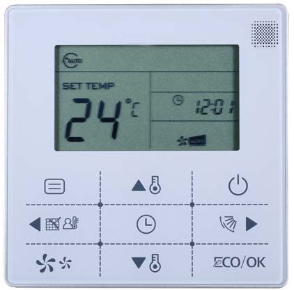
2III. DESCRIZIONE FILOCOMANDO REMOTO
Ricevitore segna le
Modalità di operazione
Icona Lock
Icona di trasmissione
Icona Funzione
Indicatore
Temp. di impostazione Timer/Orologio
Velocità di
Icona di operazione funzionamento
Icona Swing
Tasto modalità
Tasto ON/OFF
Tasto “Sinistra”
Dasto “Destra”
Tasto velocitàventilatore Tasto ECO /OK
Tasto impostazione Temp. Tasto impostazione Timer/Orologio
IV. ISTRUZIONI DI UTILIZZO
1. Funzione ricezione segnale a distanza
Sul filocomando remoto WRC11 è presente il ricevitore del segnale per il telecomando infrarosso. È possibile utilizzare
il telecomando per controllare il funzionamento del condizionatore attraverso il segnale infrarosso, quando il sistema è
stato acceso.
CAUTELA
Il filocomando non riceve l'istruzione del controllo dell’oscillazione aletta.
Per l'unità interna con la funzione swing, è possibile utilizzare direttamente il telecomando per controllare l’oscillazione
delle alette attraverso il pannello display dell'unità interna, o utilizzare il tasto swing sul filocomando per controllare
l’oscillazione delle alette dell'unità interna.
2. Accensione/Spegnimento condizionatore
Premendo il tasto ON/OFF nello stato OFF, l’unità si accenderà e l’icona di funzionamento sarà illuminata.
Premendo il tasto ON/OFF nello stato ON, l’unità si ferma di funzionare e l’icona di funzionamento si spegnerà.
3. Impostazione Modalità
Premere questo tasto per selezionare la modalità di funzionamento. Ogni volta che il tasto viene premuto, la modalità di
funzionamento cambierà a sua volta come segue:
AUTO → RAFFREDDAMENTO → DEUMIDIFICAZIONE → RISCALDAMENTO → VENTILAZIONE.
Note: Se il filocomando viene impostato su solo raffreddamento, la modalità di riscaldamento verrà disattivata.
4. Impostazione velocità ventilatore
Durante il funzionamento in modalità di raffreddamento, riscaldamento e ventilazione, è possibile premere il tasto FAN
SPEED in modo di regolare la velocità del ventilatore. Dopo ogni pressione sul tasto la velocità del ventilatore varia
come segue: AUTO → BASSA → MEDIA → ALTA → AUTO.
La regolazione della velocità del ventilatore non è consentita durante il funzionamento in modalità AUTO e
deumidificazione e la velocità della ventilatore di default è auto.
5. Impostazione temperatura
Durante il funzionamento in modalità AUTO, raffreddamento, deumidificazione riscaldamento, usare i tasti di
regolazione e per selezionare la temperatura nell’intervallo 17°C ~ 30°C (o 62°F ~ 88°F).
Nota: Durante il funzionamento in modalità di ventilazione, la temperatura non può essere regolata.
6. Impostazione Timer on e Timer off
Premere il tasto di impostazione timer/orologio, per poi accedere all’impostazione della funzione timer on, il display
mostra simultaneamente l’icona e l’indicatore .
3Utilizzare i tasti di regolazione e per impostare l’orario timer on per accendere il condizionatore.
Quando il tempo impostato è inferiore di 10 ore, ogni volta viene premuto il tasto o l’orario Aumenta o
diminuisce di 0.5 ora.
Quando il tempo impostato è oltre 10 ore, ogni volta viene premuto il tasto o l’orario aumenta o diminuisce
di 1 ora, il tempo massimo di impostazione del timer on/off è 24 ore.
Al termine dell’impostazione del timer premere il tasto o attendere 5 secondi per confermare l’impostazione e
uscire dall’impostazione.
Premere il tasto di impostazione timer/orologio per accedere all’impostazione della funzione timer off, il display mostra
simultaneamente l’icona e l’indicatore .
Nota: La procedura di impostazione del timer off è identica a quella del timer ON.
CAUTELA: È possibile annullare l’impostazione del timer ON/OFF, impostando l’orario di accensione e di
spegnimento auto sulle 0.0h.
7. Impostazione orologio
Premere il tasto timer/clock per circa 3 secondi, per poi accedere all’impostazione dell’orologio.
L’indicatore dell’ora inizia a lampeggiare sul display, e poi utilizzare i tasti e per regolare l’orario.
Al termine dell’impostazione dell’ora, premere il tasto “destro” od il tasto “sinistro” per passare all’impostazione
dei minuti, quando l’indicatore dei minuti inizia a lampeggiare, premere i tasti e d’impostazione per regolarli.
Alla fine dell’impostazione dell’orologio, premere il tasto o attendere 5 secondi per confermare l’impostazione e
uscire dall’impostazione.
8. Funzionamento ECO
In modalità di raffreddamento e riscaldamento, premendo il tasto è possibile impostare il funzionamento
economico.
Sotto lo stato di funzionamento ECO, l’unità funziona a velocità di ventilazione auto, e temperatura di impostazione di
26°C in raffreddamento e 22°C in riscaldamento.
Nota: Il funzionamento ECO è disponibile solamente se l’unità è dotata di questa funzione.
9. Blocco filocomando remoto
Premere simultaneamente i tasti di regolazione e per attivare il blocco del filocomando remoto e l’icona
si illuminerà sul display.
Quando è attivata la funzione blocco, il filocomando non risponde alla pressione dei tasti e alle istruzioni del
telecomando.
Premere simultaneamente di nuovo i tasti di regolazione e per annullare il blocco dei tasti del filocomando.
10. Funzione promemoria di pulizia del filtro
Il filocomando è dotato della funzione di memorizzazione della durata totale di operazione dell'unità interna, quando
viene raggiunto l’orario totale di operazione programmato esso significa che la pulizia del filtro dell'aria dell'unità
interna deve essere effettuata.
Premere a lungo il tasto per 3 secondi, per cancellare l'icona che ricorda la pulizia e si ricalcola il tempo totale di
funzionamento dell'unità interna.
CAUTELA: Il valore di impostazione predefinito della funzione di promemoria è di 2500 ore, e può essere
cambiato a 1250 ore, 5000 ore o 10000 ore. Per quanto riguarda la procedura impostazione, si raccomanda di
consultare il manuale di installazione.
411. Funzione Swing
Se l'unità interna è dotata della funzione swing, premere il tasto destro per regolare la direzione uscita aria
dell'unità interna. Premendo questo tasto per una durata di 3 secondi si può attivare o disattivare la funzione di
oscillazione automatica delle alette d’aria, l'icona swing sarà illuminata quando si attiva la funzione di oscillazione
automatica.
12. Funzione Follow Me
Quando l’unità è in modalità di operazione auto, raffreddamento o riscaldamento, premere il tasto per attivare la
funzione Follow Me, premere nuovamente questo tasto per disattivare la stessa funzione. Il cambiamento della
modalità operativa condurrà anche alla disattivazione della funzione precedente.
Quando la funzione Follow Me è attivata, l'icona sarà illuminata ed il display del filocomando visualizza la
temperatura ambiente rilevata dal sensore locale e trasmette il valore di temperatura all'unità interna ogni 3 minuti.
V. CERTIFICAZIONE - TECNICA E REQUISITI
● EMC deve essere conforme alla certificazione CCC.
5PARTE INSTALLAZIONE
I. PRECAUZIONI DI SICUREZZA
■ Leggere le istruzioni per la sicurezza prima dell’installazione.
■ Le seguenti indicazioni devono essere seguite con cura per la corretta installazione del filocomando.
■ Confermare che nessuna anomalia è stata riscontrata durante il test di funzionamento dopo la completa installazione,
dopodiché consegnare il manuale all’utente.
■ Descrizione indicazioni
SIMBOLO SIGNIFICATO
AVVERTIMENTO Indica che un non corretto uso può causare gravi ferite alle persone e rischio di morte.
CAUTELA Indica che un non corretto uso o rispetto delle istruzioni può causare danni a persone e cose.
Installazione deve essere eseguita da personale qualificato.
L’installato da personale non qualificato può incorrere in un rischio di scosse elettriche o di cortocircuito.
Le istruzioni di questo manuale devono essere seguite durante l’installazione.
Una non corretta installazione può causare scosse elettriche o cortocircuito.
Non smontare il condizionatore d’aria per scopi specifici.
Lo smontaggio e montaggio deve essere fatto da personale qualificato in caso contrario si possono verificare
surriscaldamenti o funzionamento anomalo.
CAUTELE
Non installare l’unità in luoghi dove vi possono essere perdite di gas infiammabili.
Gas infiammabile a contatto con i circuiti elettrici potrebbe causare un incendio.
I cavi elettrici devono essere conformi alle caratteristiche del filocomando.
In caso contrario si corre il rischio di surriscaldamenti con rischio di corto circuito ed incendio.
Non installare il filocomando in prossimità delle lampade.
Cioè per evitare che il segnale di comunicazione possa essere disturbato. (Riferirsi alla figura seguente)
Non installare il dispositivo in luoghi dove vi sia olio, gas od altre sostanze corrosive.
6II. ACCESSORI DI INSTALLAZIONE
No. Name Q.tà Note
1 Filocomando 1 /
2 Viti di montaggio M4×25 2 Utilizzate per il montaggio sulla scatola elettrica
3 Manuale di utilizzo e 1 /
4 Viti in plastica 2 Utilizzate per il fissaggio alla scatola elettrica
Cavo di collegamento per Se necessario per il collegamento tra il cavo di
5 1
pannello ricevitore recezione e il cavo schermato a 5 fili.
Preparazioni per l’installazione
Preparati il seguente materiale per l’installazione.
No. Nome Q.tà Note
1 Scatola elettrica 1 /
2 Cavo a 4 fili schermati 1 RVVP-0.5mm2×5
3 Tubo di collegamento 1 Preinstallato nel muro, massima lunghezza 15m
4 Caciavite Phillips 1 Per fissaggio viti ad intaglio a croce
5 Cacciavite a taglio 1 Per svitare il coperchio posteriore del filocomando
Note per l’installazione del filocomando
1) Questo manuale contiene informazioni sull’installazione del filocomando. Si raccomanda di riferirsi al manuale di
installazione delle unità interne per il collegamento tra filocomando ed unità interna.
2) L’alimentazione del filocomando è in bassa tensione. Non collegarlo con tensione standard (220V/380V), e non porre
i cavi del filocomando nello stesso tubo di collegamento dei cavi di alimentazione elettrica.
3) Il cavo schermato deve essere messo a terra, altrimenti il segnale potrebbe risultare disturbato.
4) Qualora sia necessario allungare i cavi è opportuno saldare le giunzioni od adottare degli appositi connettori.
5) Al termine del collegamento elettrico, non utilizzare il Megger per controllare l’isolamento del cavo segnale.
7III. PROCEDURA DI INSTALLAZIONE
Cavo di collegamento con il pannello ricevitore (display unità interna)
(accessory)
A
B
C
D
E Parte A
Pannello ricevitore
Cavo schermato a 5 fili preinstallato nel muro (display dell’unità interna)
1) Tagliare il cavo a 5-fili di collegamento del pannello ricevitore del segnale (accessorio) in due parti A e B (la parte A è
quella con il connettore a 5-fili più grande mentre e la parte B è quella con connettore piccolo).
2) Collegare il connettore a 5-fili della parte A con il terminal a 5-fili del pannello ricevitore segnale, riferirsi alla figura
sopra.
3) Collegare il cavo a 5-fili preinstallato nel muro alle altre 5 estremità della parte A del cavo del pannello ricevitore
segnale. Accertarsi che i terminali (A/B/C/D/E) del filocomando siano collegati con i rispettivi terminali (A/B/C/D/E) dei
cavi di commutazione segnale, riferirsi alla figura sopra.
4) Collegare i fili del lato tagliato del cavo del pannello ricevitore segnale (parte B) con il cavo preinstallato nel muro a 5
fili, riferirsi alla figura sotto.
Cavo schermato a 5 fili
A
preinstallato nel muro
B
C
D
E
Parte B
Installazione del coperchio posteriore del filocomando
5) Inserire il coperchio posteriore del filocomando nella
scatola elettrica utilizzando le viti a testa con intaglio
(accessorio) e rimuovere il coperchio posteriore del
filocomando, si riferisce a destra. (Riferirsi alla figura
destra)
6) Regolare la lunghezza delle due viti di plastica dell'accessorio per la lunghezza standard dal punto di fissaggio della
scatola elettrica alla parete. Assicurarsi che le due vite di fissaggio il coperchio del filcomando sono a livello e verticali
rispetto alla superficie della parete.
7) Far passare la parte B del cavo segnale del pannello ricevitore attraverso il foro dell’apertura del filocomando.
Assicurarsi che il coperchio posteriore del filocomando è a livello.
8) Inserire il piccolo connettore a 5-fili della parte B del cavo di connessione del pannello ricevitore con il terminale a 5
fili del pannello PCB del filocomando uno a uno, quindi fissare il coperchio il coperchio, riferirsi alla figura sotto.
Parte B
8Note:
- Un serraggio eccessivo della vite può causare la deformazione del coperchio posteriore e il danneggiamento del
display LCD.
- Assicurarsi che il coperchio del comando è a livello dopo l'installazione, e quindi fissare di nuovo al coperchio
inferiore.
- Durante l'installazione, riservare una certa lunghezza del cavo di collegamento per agevolare la manutenzione del
filocomando.
IV. SCHEMA DI CABLAGGIO CON IL L’UNITÀ INTERNA
Scatola elettrica dell’unità interna
Display unità interna
(Pannello ricevitore)
Scheda di controllo unità interna Connettore a 5 fili
Cavo schermato a 5 fili
Parte posteriore
del filocomando
r
9ITALIANO
ENGLISH
INDEX
USER’S PART ..................................................................................................... 11
I. SAFETY PRECAUTIONS .................................................................................................. 11
II. TECHNICAL SPECIFICATIONS ...................................................................................... 11
III. WIRED REMOTE CONTROLLER OUTLOOK ................................................................ 12
IV. OPERATION INSTRUCTIONS ....................................................................................... 12
1. Remote signal receiving function .......................................................................................... 12
2. On and Off the air-conditioner ............................................................................................... 12
3. Set the operating mode ........................................................................................................... 12
4. Fan speed setting .................................................................................................................... 12
5. Temperature setting ............................................................................................................... 12
6. Timer on and Timer off setting .............................................................................................. 12
7 Clock setting ............................................................................................................................ 13
8 ECO operation ......................................................................................................................... 13
9 Lock the wired remote controller ............................................................................................ 13
10. Air filter cleaning reminding function .................................................................................. 13
11. Swing Function...................................................................................................................... 13
12. Follow Me Function ............................................................................................................... 14
V. TECHNIQUE CERTIFICATION AND REQUIREMENT .................................................... 14
INSTALLER’S PART........................................................................................... 15
I. SAFETY PRECAUTIONS .................................................................................................. 15
II. INSTALLATION ACCESSORIES..................................................................................... 16
III. INSTALLATION PROCEDURE ....................................................................................... 17
IV. WIRING DIAGRAMS WITH AIR CONDITIONING INDOOR UNIT ................................. 18
10USER’S PART
I. SAFETY PRECAUTIONS
The following contents are stated on the product and the operation manual, including usage, precautions against
personal harm and property loss, and the methods of using the product correctly and safely. After fully understanding
the following contents (identifiers and icons), read the text body and observe the following rules.
■ Identifier description
Identifier Meaning
Means improper handling may lead to personal death or severe severe injury.
Warning
Means improper handling may lead to personal injury or property loss.
Caution
NOTE
1) “Harm” means injury, burn and electric shock which need long-term treatment but need no hospitalization.
2) “Property loss” means loss of properties and materials.
■ Icons description
Icon Meaning
It indicates forbidding. The forbidden subject-matter is indicated in the icon or by images or characters
aside.
It indicates compulsory implementation. The compulsory subject-matter is indicated in the icon or by
images or characters aside.
■ Warning
Please entrust the distributor or professionals to install the unit. The installers must have the relevant
know-how.
Warning Improper installation performed by the user without permission may cause fire, electric shock, personal
injury or water leakage.
Do not spray flammable aerosol to the wired remote controller directly. Otherwise, fire may occur.
Do not operate with wet hands or let water enter the wired remote controller. Otherwise, electric shock
may occur.
II. TECHNICAL SPECIFICATIONS
● Main parameters
Input voltage DC +5V
Ambient temperature -5°C ~ 43°C
Ambient humidity RH40% ~ RH90%
Electric control safety meets GB4706.32-2004 and GB/T7725-2004 requirements.
● Main functions
Main functions of this wired remote controller as follows:
1. Connect to the indoor unit display panel through the 5-core shielding cable;
2. Through the button operations to set the action mode;
3. Liquid crystal display function.
11III. WIRED REMOTE CONTROLLER OUTLOOK
Remote Receivin g
Wind ow
Operating Mo de
Locking Icon
Transmitting Ic on
Function Icon
Timer/Clock
Settin g Temperatu re Display Area
Operetion Ic on Operating Fan Speed
Swing Icon
Mode Butt on
ON/OFF Button
Left Butt on Right Button
Fan Speed Butt on ECO /OK Button
Temp. Setting Butt on Timer/Clock Setting Butt on
IV. OPERATION INSTRUCTIONS
1. Remote signal receiving function
The wired remote controller can be a remote signal receiving device; you can use the wireless remote controller to
control the air-conditioner through the wired remote controller when the system has been powered on.
CAUTION
The wired remote controller will not receive the swing controlling instruction.
For the indoor unit with swinging function, you can directly use the wireless remote controller to control swinging
through the display panel of the indoor unit, or use the swing button on the wired remote controller to control the indoor
unit for swinging.
2. On and Off the air-conditioner
Press the On/Off button to control the indoor unit on and off status.
When the unit is turned off, press the ON/OFF button, the unit will be turned on and the operating icon lights up.
When the unit is turned on, press the ON/OFF button, the unit will be turned off and the operating icon lights off.
3. Set the operating mode
Press the mode button to set the operating mode, after each button press the operation mode will circle as follow:
AUTO→COOL→DRY→HEAT→FAN →AUTO
When the controller has been set to cool-only, then there is no HEAT mode.
4. Fan speed setting
Under COOL, HEAT and FAN modes, press the fan speed button can adjust the fan speed setting.
After each fan speed button press will circle as follow:
AUTO→LOW→MID→HIGH→AUTO.
Under AUTO and DRY modes the fan speed is not adjustable and the default fan speed is auto.
5. Temperature setting
Under AUTO, COOL, DRY, HEAT modes, press the temperature setting buttons and to set the temperature,
the adjusting range is 17°C ~ 30°C (or 62°F ~ 88°F).
The setting temperature cannot be adjusted under FAN mode.
6. Timer on and Timer off setting
Press the timer/clock setting button, then enter into the timer on setting status, and the screen will display and .
12Press and buttons to adjust the timer. when the timer setting is less than 10 hours, each press or will
increase or decrease 0.5 hour. When the timer setting is more than 10 hours, each press or will increase or
decrease 1 hour, the maximum timer setting is 24 hours.
After finish adjusting the timer on setting, press the button or wait for 5 seconds to confirm and exit the timer
on setting.
Under the timer on setting status, press the timer/clock setting button, then enter into the timer off setting status, and
the screen will display and .
The setting method of timer off is the same as the timer on.
Under timer setting state, set the timer on and timer off to be 0.0h can cancel timer on and timer off.
CAUTION
If the wired remote controller has been set timer on/ off, press the ON/OFF to turn on/ turn off the unit then the timer will
be cancelled simultaneously.
7. Clock setting
Long press the timer/clock setting button for 3 seconds, then enter into the clock setting status.
The hour position of the clock will flash, and can press and buttons to adjust the hour value.
After finishing the hour setting, press left button or right button to switch to minute position setting, then the
minute position will flash, press and buttons to adjust the minute value.
After finish the clock setting, press the button or wait for 5 seconds to confirm and exit the setting state.
8. ECO operation
Press the button to enter ECO operation when the unit is turned on and is cooling or heating.
Under ECO operation, the initial fan speed is auto, and the setpoint is 26°C for COOL mode, and 22°C for HEAT mode.
ECO operation is available only when the IDU equipped with this function.
9. Lock the wired remote controller
Press the temperature adjusting buttons and buttons simultaneously, the wired remote controller enters into
locking state, and the locking icon will be lighted up.
Under the locking state, the wired remote controller will not respond to the buttons pressing and the control instruction
from the wireless remote controller.
Simultaneously press and the temperature adjusting buttons and again can cancel the locking state.
10. Air filter cleaning reminding function
The wired remote controller records the total running time of the indoor unit, when the accumulated running time
reaches the pre-setting value, the air filter of the indoor unit need to be cleaned.
Long press for 3 seconds, and reset the reminding icon and the wired remote controller will re-accumulate the
total running time of the indoor unit.
CAUTION
The default setting value of the reminding function is 2500 hours, and it can change to be 1250 hours, 5000 hours or
10000 hours. The setting methods please refer to the installation manual.
11. Swing Function
If the indoor unit supports swing function, press the right button to adjust the air outlet direction of the indoor unit.
Long press this button for 3 seconds can turn on or turn off the auto swing function, the swing icon will be lighted up
when the auto swing function is turned on.
1312. Follow Me function
When the system is running and the operating mode is AUTO, COOL or HEAT, press the button will activate
the Follow Me function, press this button again to deactivate the function. Operating mode changeover will deactivate
the function as well.
When the Follow Me function is activated, the icon will be light up, the wired remote controller will display room
temperature read from the local sensor, and transmit the temperature value to the indoor unit every 3 minutes.
V. TECHNIQUE CERTIFICATION AND REQUIREMENT
● EMC should conform to the CE certification.
14INSTALLER’S PART
I. SAFETY PRECAUTIONS
■ Read the safety precautions carefully before installing the unit.
■ Stated below are important safety issues that must be obeyed.
■ Confirm there is no abnormal phenomena during test operation after complete, then hand the manual to the user.
■ Meaning of marks:
Symbol Meaning
Warning Means improper handling may lead to personal death or severe injury.
Caution Means improper handling may lead to personal injury or property loss.
WARNING
Please entrust the distributor or professionals to install the unit.
Installation by other persons may lead to imperfect installation, electric shock or fire.
Strictly follow this manual.
Improper installation may lead to electric shock or fire.
Reinstallation must be performed by professionals.
Improper installation may lead to electric shock or fire.
Do not disassemble your air conditioner at will.
A random disassembly may cause abnormal operation or heating, which may result in fire.
CAUTION
Do not install the unit in a place vulnerable to leakage of flammable gases.
Once flammable gases are leaked and left around the wire controller, fire may occur.
The wiring should adapt to the wire controller current.
Otherwise, electric leakage or heating may occur and result in fire.
Do not place the wired remote controller near the lamps, to avoid the remote signal of the controller to be
disturbed. (refer to the right figure)
15II. INSTALLATION ACCESSORIES
No Name Quantity Remarks
1 Wire controller 1 ----------------
This accessory is used when install the wire
2 M4×25 Cruciform slot screw 2 controller inside the electric cabinet (For
Mounting on the Wall)
3 Installation and operation manual 1 ---
This accessory is used when install the wire
4 Plastic Bolt 2
control inside the electric cabinet
For connect between the signal received wire
5 The connective wires of signal receiving panel 1
and shielded 5-core cable
Please filed install the following accessory
No Name Quantity Remarks
Universal electric cabinet specification, pre-embed
1 Electric cabinet 1
it into wall.
2 Shielded 5-core cable 1 Pre-embed RVVP-0.5mm 2×5 into wall.
Pre-embed into wall, the longest length should not
3 Wire configured tube (insulated sheath) 1
exceeding than 15m.
4 Phillips screwdriver 1 For install Cruciform slot screw.
5 Slotted head screwdriver 1 For unscrew the bottom cover of wire controller.
Note to installation of wire controller
1) This installation manual contains information about the procedure of installing Wired Remote Controller. Please refer
to Indoor Unit Installation Manual for connecting between Wired Remote Controller and Indoor Unit.
2) Circuit of Wired Remote Controller is low voltage circuit. Never connect it with a standard 220V/380V circuit or put it
into a same Wiring Tube with the circuit.
3) The shield cable must be connected stable to the ground, or transmission may fail.
4) Do not attempt to extend the shield cable by cutting, if it is necessary, use Terminal Connection Block to connect.
5) After finishing connection, do not use Megger to have the insulation check to the signal wire.
16III. INSTALLATION PROCEDURE
Connective wires for the signal received panel (accessory)
A
B
C
D
E A part
Signal received panel
The shielded 5-core wire pre-embedded into wall. of indoor unit
1) Cut off the connective wires for the signal received panel (accessory) from the middle (no protecting sleeve part),
divide to be A, B parts, and the A part has big 5-core connector as well as B part has small 5-core connector.
2) Connect the big 5-core connector of the A part signal received panel connecting wire group with the 5-core terminal
of signal received panel, refers to the above.
3) Please connect the other side (cut-off side) of A part signal received panel with the wall pre-bedded 5-core cable
reliability, refers to the above.
4) Please connect the cut-off side of B part signal received panel with the wall pre-bedded 5-core cable reliability, refers
to the below figure.
The shielded 5-core wire
A pre-embedded into wall .
B
C
D
E
B part
- Connecting wires of two sides in digital display pipe must be connected one to one.
5) Insert to the bottom cover to the electric cabinet by the accessory slotted head screws, and take down the bottom
cover of wire controller, refers to the below figure.
6) Adjust the length of two plastic bolts base on the length of through out from standard electric cabinet to the wall.
Confirm the two bolts fixing in the cabinet are in the same length and vertical to the wall surface.
7) Make the connecting wires of B part signal receiving panel to go through the hole of back cover, and use Make sure
the back cover of wire controller in the same level, refers to the below.
B part
178) Insert the small 5-core connector of the B part signal receiving panel connecting wire group with the 5-core terminal
of wire controller PCB panel one to one, and then cover the wire controller with the back cover, refers to the below.
B part
- Over tighten the screw would cause rear cover deformed and LCD damage.
- When installation, please maintain the screws and wire controller at the same height level without deformed.
- When installation, please reserve a certain length of wire controller connective cable for future maintenance to take off
the wire controller.
IV. WIRING DIAGRAMS WITH AIR CONDITIONING INDOOT UNIT
Wiring diagram of the wire controller and the air conditioning indoor unit.
Indoor unit electric control box
Indoor unit display panel
Indoor unit 5-core connecting wire group
electric control
panel 5-core shielding wire
The back of
the wire
controller
18Serie / Series / Serie / Serie
MANUALE UTENTE - INSTALLATORE PER
FILOCOMANDO REMOTO
REMOTE WIRE CONTROLLER USER’S -
INSTALLER’S MANUAL
Emissione / Issue Sostituise / Supersade I prodotti elettrici ed elettronici di eventuale scarto non dovranno essere disposti
Ausgabe / Emission Ersetzt / Remplace con i normali rifiuti domestici, ma smaltiti a norma di legge RAEE in base alle
direttive Europee 2002/96/CE e suc-cessive modifiche 2003/108/CE,
informandosi presso il Comune di residenza o presso il rivenditore nel caso in cui
01 - 2018 - il prodotto venga sostituito con uno analogo.
Possible electrical or electronic rejected devices/products should not be located
Catalogo / Catalogue / Katalog / Catalogue together with normal domestic waste, but disposed according to the current
WEEE law in compliance with the 2002/96/EC European Directive and with the
MUI14015I1201-00 2003/108/EC following amendments. Should you decide to replace this product
with a new one, please, address your local Administration or your reseller.Puoi anche leggere