Comando remoto a filo Wire remote control - INSTRUZIONI PER USO USE INSTRUCTIONS - Ferroli
←
→
Trascrizione del contenuto della pagina
Se il tuo browser non visualizza correttamente la pagina, ti preghiamo di leggere il contenuto della pagina quaggiù
Comando remoto a filo
                                    Wire remote control
Cod. 3QE45990 - Rev. 00 - 05/2019

                                       INSTRUZIONI PER USO
                                       USE INSTRUCTIONS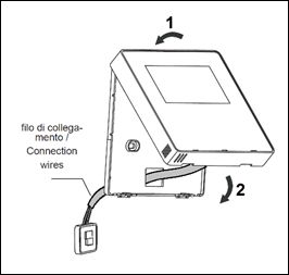
Comando remoto a filo

                                                                                                  SOMMARIO
GENERALITA’ .  .  .  .  .  .  .  .  .  .  .  .  .  .  .  .  .  .  .  .  .  .  .  .  .  .  .  .  .  .  .  .  .  .  .  .  .  .  .  .  .  .  .  .  .  .  .  .  .  .  .  .  .  .  .  .  .  .  .  . 3
     Norme generali di sicurezza  . . . . . . . . . . . . . . . . . . . . . . . . . . . . . . . . . . . . . . . . . . . . . . . 3
     Per l’utente . . . . . . . . . . . . . . . . . . . . . . . . . . . . . . . . . . . . . . . . . . . . . . . . . . . . . . . . . . . . .3
     Le unità sono contrassegnate con il seguente simbolo . . . . . . . . . . . . . . . . . . . . . . . . . . . 3
INSTALLAZIONE  .  .  .  .  .  .  .  .  .  .  .  .  .  .  .  .  .  .  .  .  .  .  .  .  .  .  .  .  .  .  .  .  .  .  .  .  .  .  .  .  .  .  .  .  .  .  .  .  .  .  .  .  .  .  .  .  . 4
     Precauzioni  . . . . . . . . . . . . . . . . . . . . . . . . . . . . . . . . . . . . . . . . . . . . . . . . . . . . . . . . . . . . 4
     Dimensioni . . . . . . . . . . . . . . . . . . . . . . . . . . . . . . . . . . . . . . . . . . . . . . . . . . . . . . . . . . . . . 4
     Collegamenti elettrici  . . . . . . . . . . . . . . . . . . . . . . . . . . . . . . . . . . . . . . . . . . . . . . . . . . . . 5
     Schema di Collegamento . . . . . . . . . . . . . . . . . . . . . . . . . . . . . . . . . . . . . . . . . . . . . . . . . .5
USO .  .  .  .  .  .  .  .  .  .  .  .  .  .  .  .  .  .  .  .  .  .  .  .  .  .  .  .  .  .  .  .  .  .  .  .  .  .  .  .  .  .  .  .  .  .  .  .  .  .  .  .  .  .  .  .  .  .  .  .  .  .  .  .  .  .  .  . 7
     Descrizione tasti e funzioni  . . . . . . . . . . . . . . . . . . . . . . . . . . . . . . . . . . . . . . . . . . . . . . . . 7
     Display . . . . . . . . . . . . . . . . . . . . . . . . . . . . . . . . . . . . . . . . . . . . . . . . . . . . . . . . . . . . . . . . 7
     Accensione\Spegnimento  . . . . . . . . . . . . . . . . . . . . . . . . . . . . . . . . . . . . . . . . . . . . . . . . . 8
     Modifica dei parametri impostati -temperatura – timer - funzione . . . . . . . . . . . . . . . . . . . 8
     Selezione della modalità di funzionamento “Mode”  . . . . . . . . . . . . . . . . . . . . . . . . . . . . . 8
     Il settaggio della velocità del ventilatore  . . . . . . . . . . . . . . . . . . . . . . . . . . . . . . . . . . . . . . 8
     Il settaggio dell’oscillazione “Swing”  . . . . . . . . . . . . . . . . . . . . . . . . . . . . . . . . . . . . . . . . . 8
     Impostazione “Timer”  . . . . . . . . . . . . . . . . . . . . . . . . . . . . . . . . . . . . . . . . . . . . . . . . . . . . 8
     Il settaggio della funzione “Sleep”  . . . . . . . . . . . . . . . . . . . . . . . . . . . . . . . . . . . . . . . . . . 9
     Funzioni opzionali  . . . . . . . . . . . . . . . . . . . . . . . . . . . . . . . . . . . . . . . . . . . . . . . . . . . . . . . 9
     Visualizzazioni sul display  . . . . . . . . . . . . . . . . . . . . . . . . . . . . . . . . . . . . . . . . . . . . . . . . 12
     Altre impostazioni  . . . . . . . . . . . . . . . . . . . . . . . . . . . . . . . . . . . . . . . . . . . . . . . . . . . . . . . 14
     Procedura di impostazione  . . . . . . . . . . . . . . . . . . . . . . . . . . . . . . . . . . . . . . . . . . . . . . . . 14
     Display errori . . . . . . . . . . . . . . . . . . . . . . . . . . . . . . . . . . . . . . . . . . . . . . . . . . . . . . . . . . . 15
MANUTENZIONE .  .  .  .  .  .  .  .  .  .  .  .  .  .  .  .  .  .  .  .  .  .  .  .  .  .  .  .  .  .  .  .  .  .  .  .  .  .  .  .  .  .  .  .  .  .  .  .  .  .  .  .  .  .  .  .  . 17
     Pulizia dei filtri dell’unità interna . . . . . . . . . . . . . . . . . . . . . . . . . . . . . . . . . . . . . . . . . . . . .17
     Pulizia dell’unità interna . . . . . . . . . . . . . . . . . . . . . . . . . . . . . . . . . . . . . . . . . . . . . . . . . . . 17
     Pulizia dell’unità esterna  . . . . . . . . . . . . . . . . . . . . . . . . . . . . . . . . . . . . . . . . . . . . . . . . . . 17

2                          IT                                         Cod. 3QE45990 - Rev. 00 - 05/2019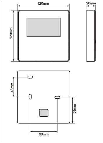
Comando remoto a filo
                                            GENERALITA’
Norme generali di sicurezza
Informazioni sulla documentazione
▪ Seguire con attenzione le precauzioni descritte in questo documento.
▪ Tutte le attività descritte nel manuale di installazione devono essere eseguite da un installatore
qualificato.
▪ Installazione da parte di persone non qualificate può causare dei malfunzionamenti, scosse elet-
triche o incendi.
▪ Un’installazione inpropria potrebbe provocare scosse elettriche o incendi.

Il cablaggio elettrico deve essere eseguito in
conformità a quanto indicato in questo manuale.
In caso contrario, dispersioni elettriche o surriscal-
damento potrebbero causare un incendio.
Nessuna forza esterna deve essere applicata
al terminale.
In caso contrario, potrebbe danneggiarsi il filo di
collegamento con possibile surriscaldamento e
conseguente rischio di incendio.
Non posizionare il controllore in prossimità di
lampade, per evitare disturbi elettromagnetici
sul segnale.
Per l’utente
▪ Se non si è sicuri di come far funzionare l’unità, contattare l’installatore.
▪ L’apparecchio non è destinato all’uso da parte di persone, compresi i bambini, con ridotte capacità
fisiche, sensoriali o mentali, o la mancanza di esperienza e conoscenza, a meno che non siano con-
trollati o istruiti all’uso dell’apparecchio da una persona responsabile della loro sicurezza . I bambini
devono essere sorvegliati per assicurarsi che non giochino con il prodotto.
AVVISO
▪ Non collocare oggetti o apparecchiature sulla parte superiore dell’unità.
▪ Non sedersi o salire sull’unità.

Le unità sono contrassegnate con il seguente simbolo
Ciò significa che i prodotti elettrici ed elettronici salute umana. Per ulteriori informazioni, contattare
non devono essere mescolati con i rifiuti dome- l’installatore o autorità locali.
stici non differenziati. Non cercare di smontare il
sistema da soli: lo smantellamento del sistema, il
recupero del refrigerante, dell’olio e di altre parti
deve essere eseguita da personale autorizzato e
devono essere conformi alla normativa vigente. Le
unità devono essere trattate in un impianto di trat-
tamento specializzato per il riutilizzo, il riciclaggio e
il recupero. Assicurandosi che questo prodotto sia
smaltito correttamente, si contribuisce a prevenire
potenziali conseguenze negative per l’ambiente e la

                                  Cod. 3QE45990 - Rev. 00 - 05/2019                       IT            3
Comando remoto a filo
INSTALLAZIONE
Precauzioni
Luogo di installazione
Non installare l’unità in un luogo con molto olio, vapore, gas solforosi, altrimenti, il prodotto può
deformarsi e danneggiarsi.
Nota: Il controllore ha un sensore di temperatura a bordo, il valore di temperatura misurato può essere
preso come riferimento per il funzionamento della macchina. E’ opportuno quindi che il comando sia
posizionato in una zona significativa per la lettura della temperatura ambiente, quindi lontano da vetri,
finestre, nascosto da tendaggio o zone a temperatura particolare.
Preparazione prima dell’installazione
Il kit Controllore remoto a filo è composto da:
ID Descrizione Qtà
1 Controllore remoto a filo 1
2 Cavo di collegamento 4 fili 5 metri 1
3 Manuale di installazione e uso 1
Dimensioni
4 IT Cod. 3QE45990 - Rev. 00 - 05/2019Comando remoto a filo
Collegamenti elettrici
1) Questo manuale di installazione contiene informazioni sulla procedura di installazione del controllore
remoto. Si prega di fare riferimento anche al manuale di installazione dell’unità per il collegamento
controllore - unità.
2) Il circuito del controllore remoto è a bassa tensione. Non collegarlo alla rete di alimentazione
elettrica (230V / 400V) o ad altre fonti ad alta tensione. Non posare il cavo di connessione assieme
a cavi di potenza.
Schema di Collegamento
Negli schemi sotto, indicazione dei collegamenti da eseguire in fase di installazione.
Note:
A= Comando a filo
B= Cavo di collegamento 5 m fornito a corredo
C= Morsettiera su scatola elettrica unità interna
Si raccomanda di rispettare la sequenza dei collegamenti
RD= Rosso con terminale X1
BL= Nero con terminale X2
GN= Verde con terminale X3
YE= Giallo con terminale X4
Cod. 3QE45990 - Rev. 00 - 05/2019 IT 5Comando remoto a filo
Installazione comando
Installazione coperchio posteriore
1-Aprire il controllore come indicato in figura Punto di apertura Pannello
posteriore
Pannello
Cacciavite testa anteriore
piatta
Pannello
2-Fissare il coperchio posteriore ed assicurarsi che:
posteriore
a) il controllore sia installato correttamente a filo
parete
b) le viti di fissaggio per non deformino il coperchio
posteriore.
Installazione parte frontale
3-Inserire il cavo di collegamento. Durante l’in-
stallazione del coperchio frontale fare attenzione
a evitare possibili interferenze meccaniche tra
coperchio e filo.
filo di
collegamento
6 IT Cod. 3QE45990 - Rev. 00 - 05/2019Comando remoto a filo
USO “HEAT-CALDO”: L’unità si attiva quando la tem-
peratura impostata è piu’ alta della temperatura
Descrizione tasti e funzioni ambiente.
“FAN”. L’unità attiva solo il ventilatore per la
circolazione dell’aria”.
8. Tasto “ SWING “ per attivare/disattivare il
movimento automatico del deflettore d’aria (ove
presente flap motorizzato)
9. Tasto “FAN” permette di selezionare la velocità
della ventilazione:
automatica - bassa – media - alta - automatica
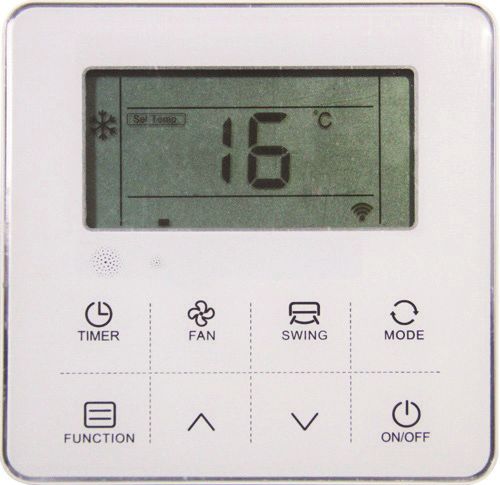
Display
fig. 1 - Tasti e funzioni
Il comando (fig. 3) è composto da una serie di tasti
e da un display che visualizza tutte le funzioni attive
ed i vari parametri necessari all’utente ed all’in-
stallatore per un corretto utilizzo dell’unità stessa.
1. Area ricevitore infrarosso e sensore luminosità.
2. Tasto “TIMER consente di attivare la funzione
fig. 2 - Display
TIMER
3. Tasto “FUNCTION” attiva o disattiva funzioni 1. Area icone Modalità di funzionamento.
speciali del condizionatore 2. Area icone Velocità Ventilatore
4. Tasto “ “, usato per alzare il valore di tem- 3. Area icone funzioni ausiliarie
peratura o tempo o dei paramenti in fase di
4. Area icone impostazioni ausiliarie
impostazione.
5. Area visualizzazione Temperature
5. Tasto “ “, usato per abbassare il valore di
temperatura o tempo o dei paramenti in fase di 6. Area visualizzazione impostazioni timer
impostazione. 7. Icone funzioni deflettori aria
6. Tasto “ “, permette l’accensione e lo spegni-
mento del condi-zionatore.
7. Tasto “MODE”, permette di selezionare il modo
di funzionamento:
AUTO - COOL - DRY – FAN. - HEAT
“AUTO”: seleziona automaticamente la moda-
lità di funzionamento più opportuna in relazione
alla temperatura ambiente iniziale (modalità
automatica).
“COOL-FREDDO”: L’unità si attiva quando la
temperatura impostata è piu’ bassa della tempe-
ratura ambiente.
“DRY-DEUMIDIFICAZIONE” per deumidificare.
Cod. 3QE45990 - Rev. 00 - 05/2019 IT 7Comando remoto a filo
Accensione\Spegnimento Il settaggio dell’oscillazione “Swing”
Premere il ON/OFF pulsante per accendere (ON) 1. Per le unità che hanno unicamente la
o spegnere (OFF). funzione oscillazione verticale delle alette:
1. Quando l’unità è in funzione, gli utenti Quando l’unità è in funzione, premere il tasto
possono regolare la modalità operativa, la “Swing” per attivare o disattivare l’oscil-
velocità del ventilatore, la temperatura impo- lazione delle alette. Quando si attiva appare
stata, le funzioni speciali e gli altri parametri l’icona “”. Se si disattiva, l’icona scompare. Se
sul controller a filo. l’unità ha la possibilità di fissare il posiziona-
mento delle alette, premere il tasto “Swing”
2. Quando l’unità è in standby, il display del
per regolare l’inclinazione nell’ordine:
controller mostra la temperatura interna
dell’ambiente (Room temp.), le altre infor- → → → → → → cancel up and
mazioni non sono visualizzate.
2. Per le unità con solo oscillazione orizzontale
delle alette: quando l’unità è in funzione pre-
Modifica dei parametri impostati mere il tasto “Swing” per attivare l’oscillazione
-temperatura – timer - funzione orizzontale. Quando si attiva, si visualizza
1. Quando l’unità è in funzione, premere i il simbolo,” ”. Alla disattivazione l’icona
tasti “▲“ o “▼“ per aumentare o diminuire scompare. Se l’unità ha la possibilità di fissare
la temperatura impostata di 1ºC. Nelle il posizionamento delle alette, premere il tasto
modalità COOL, DRY, e HEAT, l’intervallo “Swing” per regolare l’inclinazione nell’ordine
di temperature impostabile è 16ºC~32 ºC; prima mostrato.
Il controller mostra” Set temp.” per indicare
la temperatura impostata. → → → → → → cancel up and
2. Nella selezione della modalità operativa, 3. Per le unità con entrambe le funzioni oscil-
premere i tasti “▲“ o “▼“ per selezionare lazione verticale ed orizzontale. Premere
la funzione il tasto “Swing”, la modalità di oscillazione
varia nel seguente ordine:
3. Nella modalità Timer, premere i tasti “▲“ o
“▼“ per settare un timer. ↓ su e giù SWING ON
↓ su e giù SWING OFF
Selezione della modalità di funzionamento ↓ sinistra e destra SWING ON
“Mode” ↓ sinistra e destra SWING OFF
Quando l’unità sta funzionando, premere il tasto ↓ su e giù - sinistra e destra SWING ON
“MODE”, la modalità di funzionamento varierà ↓ su e giù - sinistra e destra SWING OFF
secondo il seguente ordine:
Impostazione “Timer”
La temperatura inizialmente impostata per ogni Gli utenti possono impostare il tempo di spegni-
modalità è di 24ºC, e non c’è alcuna temperatura mento quando l’unità è in funzione e impostare il
impostata e velocità automatica del ventilatore in tempo di avvio quando l’unità è spenta.
modalità FAN.
1. Premere il tasto “Timer” quando l’unità sta
funzionando, il display del controllo a filo
Il settaggio della velocità del ventilatore mostra “ Time off ” e l’utente può impostare
Quando l’unità è in funzione, premere il tasto “Fan” il timer di spegnimento della macchina;
per variare la velocità di funzionamento secondo quando l’unità è spenta, il controller a filo
il seguente ordine: mostra “ Time on “, e gli utenti possono
settare il timer di accensione della macchina.
2. Dopo essere entrati nella sezione settaggio
In modalità turbo, il display mostra turbo + l’icona Timer, il tempo settato di default è 0.5h, pre-
della velocità maggiore del ventilatore. mere quindi i pulsanti “▲“ o “▼“ per regolare
8 IT Cod. 3QE45990 - Rev. 00 - 05/2019Comando remoto a filo
il timer. Se non si preme alcun bottone per 2. Premere i tasti “▲“ o “▼“ per selezionare
10 secondi, il timer settato verrà cancellato la funzione Sleep, l’icona lampeggia.
e si ritorna allo stato no-timer. 3. Premere di nuovo il tasto “Function” per
3. Dopo aver settato il Timer, premere ancora il cancellare la funzione Sleep
tasto “Timer” per confermare. L’impostazione
del Timer ha successo e la barra temporale
smette di lampeggiare.
4. Dopo aver impostato il Timer “Timer On”, si
può aggiustare la velocità del ventilatore, la
modalità operativa, settare la temperatura
e l’oscillazione delle alette. Se non viene
settata alcuna operazione per 10 secondi,
il display torna in standby.
5. Intervallo Timer: 0.5-24 hours. Premendo i
pulsanti “▲“ o “▼“, il tempo aumenta o dimi- Funzioni opzionali
nuisce di 0.5 ore. Quando il Timer supera le Il controllo a filo a parete prevede queste
10 ore, premendo i tasti una volta, il tempo funzioni generiche, le funzioni specifiche
aumenta/diminuisce di 1 ora. del controller dipendono invece dal proprio
6. Premere il pulsante “Timer” o “ON/OFF” per particolare climatizzatore.
uscire dall’attivazione/ disattivazione Timer. Nota: nel settaggio delle funzioni, premere
qualsiasi tasto quale Timer, Fan, Swing, Mode,
ON/OFF, e Comfort per uscire dal settaggio
delle funzioni e tornare al menù principale. Se
non avviene alcuna interazione per 10secondi,
avviene l’uscita dall’interfaccia.
Entrare nelle funzioni
Premere il tasto “Function” per entrare nell’inter-
faccia selezione funzione, premere “▲“ o “▼“ per
Il settaggio della funzione “Sleep” selezionare la funzione, e quando la corrispon-
dente icona lampeggia, premere di nuovo il tasto
Funzione Sleep: L’unità interna funzionerà in base “Function” per confermare.
alla curva di temperatura Sleep preimpostata, che
crea un ambiente notturno confortevole e migliora
la qualità del sonno. Cancellare la funzione
Entrare nella funzione Sleep: Premere il tasto “Function” per entrare nell’inter-
1. In funzionamento, premere il tasto “Function” faccia selezione funzione, premere “▲“ o “▼“ per
per entrare nella selezione delle funzioni. selezionare la funzione, e quando la corrispon-
dente icona lampeggia, premere il tasto “Function”
2. Premere i tasti “▲“ o “▼“ per selezionare per cancellare.
funzione Sleep, l’icona “ “ lampeggia
in quel momento.
3. Premere il tasto “ Function” per aprire la
funzione Sleep, in quel momento l’icona “
” è accesa.
Cancellare la funzione Sleep:
1. Quando la funzione Sleep è attiva, premere
il tasto “Function” per entrare nella selezione
funzione.
Cod. 3QE45990 - Rev. 00 - 05/2019 IT 9Comando remoto a filo
Il settaggio della funzione “Turbo” Il settaggio della funzione “ECO”
Funzione Turbo: La velocità del ventilatore è
Attivare la funzione:
la massima per riscaldare/raffrescare in fretta
l’ambiente. 1. Premere il tasto “Function” per
entrare nella selezione della
Attivare la funzione: funzione.
1. Quando l’unità sta funzionando in 2. Premere i tasti “▲“ o “▼“ per
riscaldamento o raffrescamento pre- selezionare la funzione ECO,
mere il tasto “Function” per accedere in quel momento l’icona “
Eco
”
alla selezione della funzione. lampeggia.
2. Premere il tasto “▲“ o “▼“ per 3. Premere nuovamente il tasto
selezionare la funzione Turbo, a “Function” per confermare la
quel punto appare il simbolo, “ ”. funzione ECO, in quel momento
3. Premere il tasto “Function” per con- l’icona lampeggia “ ”.
Eco
fermare, in quel momento l’icona “ Cancellare la funzione:
”, appare sul display ( Turbo 1. Premere il tasto “Function” per
e l’icona di velocità maggiore entrare nella modalità selezione
possibile). della funzione.
Cancellare la funzione: 2. Premere i tasti “▲“ o “▼“ per
1. Quando la funzione turbo è attivata, selezionare la funzione ECO,
premere il tasto “Function” per in quel momento l’icona “ “ Eco
entrare nell’interfaccia selezione lampeggia.
funzione. 3. Premere nuovamente il tasto
2. Premere il tasto “▲“ o “▼“ per “Function” per cancellare la
entrare nella sezione Turbo, in quel funzione ECO.
momento lampeggia l’icona “ ”,
premendo ancora il tasto “Function”
si cancella la funzione Turbo e l’icona
sparisce.
Nota: Nelle unità senza la funzione Turbo è
comunque possibile settare il Turbo sul controller
a filo, la performance è equivalente a quella con
la massima velocità, ma le icone “ Turbo ” e “
” non appaiono.
10 IT Cod. 3QE45990 - Rev. 00 - 05/2019Comando remoto a filo
Il settaggio della funzione “Anti-fungus” Il settaggio della funzione “Clean”
Funzione Anti-fungo: Dopo lo spegnimento, il Funzione Clean: La funzione Clean può pulire
condizionatore d’aria asciuga automaticamente automaticamente l’evaporatore della macchina
l’umidità sull’evaporatore dell’unità interna, in interna, che può non solamente mantenere l’aria
modo da evitare la formazione di muffa. fresca, ma anche ridurre le conseguenze negative
del raffrescamento.
Attivare la funzione:
1. Durante le modalità COOL e Attivare la funzione:
DRY, premere il pulsante “Fun- 1. Quando l’unità è spenta, premere
ction” per entrare nella modalità il tasto “Function” per entrare
di selezione della funzione. nella selezione della funzione,
2. Premere i tasti “▲“ o “▼“ per l’icona “ Clean ” lampeggia.
selezionare la funzione Anti- 2. Premere ancora il tasto “Fun-
Fungo, in quel momento l’icona ction” per confermare l’attiva-
“ -” lampeggia. zione della funzione Clean,
3. Premere nuovamente il tasto in quel momento l’icona “ Clean ”
“Function” per attivare la fun- lampeggia.
zione Anti-Fungo, l’icona “ ” 3. Quando l’unità è accesa e la fun-
lampeggia. zione Clean attivata, il controller
Cancellare la funzione: mostra l’icona “ Clean ”, finché non
termina il funzionamento.
1. Quando è attivata la funzione
Anti-Fungo, premere il tasto
“Function” per entrare nella
modalità selezione funzione.
2. Premere il tasto “▲“ o “▼“ per
selezionare la funzione Anti-
Fungo, l’icona “ ” lampeggia.
3. Premere il tasto “Function”
nuovamente per disattivare la
funzione Anti-fungo, l’icona “
” sparisce.
Cod. 3QE45990 - Rev. 00 - 05/2019 IT 11Comando remoto a filo
Il settaggio della funzione “Light Sensation” Visualizzazioni sul display
Funzione Light Sensation: Rileva l’accensione
e lo spegnimento della luce di una lampada da Funzione “WIFI” sul display
interni e passa quindi ad una bassa velocità del
ventilatore quando la luce della lampada è spenta, Se l’unità è equipaggiata con un modulo WiFi,
il che riduce il rumore e crea un ambiente notturno l’icona “ ” si illumina sul controller.
più confortevole per gli utenti. Se l’unità non è equipaggiata, l’icona “ ” non
compare.
Attivare la funzione:
1. In funzionamento, premere il
tasto “Function” per selezionare
la funzione.
2. Premere “▲“ o “▼“ per selezio-
nare la funzione Light Sensation,
l’icona “ ” lampeggia.
3. Premere nuovamente il pulsante
“Function” per attivare la funzione
light sensation, in quell momento
l’icona ” ” lampeggia. Funzione “Blocco bambini” sul display
4. Quando la funzione Light Sen- Premere i pulsanti “▲“ o “▼“ per più di 5 secondi
sation è attivata, se la luce per entrare nella modalità blocco bambini. Viene
all’interno dell’ambiente è spenta visualizzata l’icona “ ” sul display. Il metodo di
da almeno 20 minuti, l’unità entra sbloccaggio: premere I bottoni “▲“ o “▼“ per più di
automaticamente in modalità 5 secondi o spegnere l’unità per sbloccare l’unità
Sleep. Se la luce viene accesa (“ ” non compare più).
per almeno 20 minuti, l’unità
annulla la modalità Sleep e
segue il settaggio della velocità
impostato.
Cancellare la funzione:
1. Quando la funzione è attivata,
premere il tasto “Function” per
entrare nella selezione delle
funzioni.
2. Premere i tasti “▲“ o “▼“ per Funzione “Blocco” sul display
selezionare la funzione Light Quando l’unità è controllata e bloccata da un
Sensation. controller centralizzato, il controllo a filo a parete
3. Premere nuovamente il pulsante mostra l’icona “ ”.
“Function”, e l’icona “ ” sparirà.
12 IT Cod. 3QE45990 - Rev. 00 - 05/2019Comando remoto a filo
Funzione “Muto” sul display più visualizzata. Viene inviato all’unità un segnale
Quando l’unità attiva la modalità Silenziosa, sul di ripristino della pulizia del filtro.
display appare l’icona “ ”, quando la funzione è
disattivata, scompare l’icona sul display.
Nota: Le unità senza la modalità muto possono
comunque attivarla dal controller, la velocità del
ventilatore viene ridotta al minimo ma non appare
l’icona ” ” sul display.
Funzione cambio “Celsius e Fahrenheit” sul
display
Quando gli utenti impostano Celsius come misura
valida, il controller cablato mostrerà la temperatura
in gradi Celsius. Quando gli utenti impostano
Fahrenheit come valido, il controller cablato
visualizzerà la temperatura in gradi Fahrenheit .
Funzione “Ritorno Olio / Sbrinamento” sul
display
Quando l’unità sta funzionando inSbrinamento,
l’icona “ ” lampeggia sul controller.
Quando l’unità ha finito lo Sbrinamento l’icona,”
“ sparisce.
Funzione controllo remoto
Il telecomando a filo a parete può ricevere comandi
da un telecomando ad infrarossi e modificare il
suo funzionamento.
Accendere l’unità con il telecomando ad infrarossi,
il controller a filo funziona in base allo stato impo-
stato sul telecomando ad infrarossi e visualizza
la modalità di funzionamento corrispondente
impostata.
Funzione “Ricordo pulizia filtro” sul display
Sensore di temperatura ambiente equipaggiato
Funzione di promemoria pulizia filtro: L’unità può
sul controllo a filo a parete
registrare il tempo di funzionamento, quando
raggiunge il tempo impostato dall’utente, ricorderà Quando il controller a filo è dotato di un sensore di
all’utente di pulire il filtro, in modo da evitare una temperatura ambiente e il sensore non è danneg-
mancata pulizia prolungata e il bloccaggio per giato, di default la temperatura ambiente rilevata
sporco del filtro, che può causare uno scarso dal sensore sul controller e il valore della tempe-
effetto riscaldamento/ raffreddamento, creazione ratura sono inviati al PCB principale dell’unità.
di batteri ed altri problemi. Se il controller del filo non è dotato di un sensore di
Quando il tempo di funzionamento raggiunge il temperatura ambiente o il sensore è danneggiato,
tempo impostato di promemoria di pulizia del filtro la temperatura ambiente verrà rilevata dal sensore
impostato dall’utente, l’unità segnalerà un prome- di temperatura dell’unità stessa.
moria per la pulizia del filtro tramite l’icona “ ” sul
controller cablato, che ricorda all’utente di pulire
il filtro. Premere il tasto “Timer” per 5 secondi per
annullare il promemoria, quindi l’icona non verrà
Cod. 3QE45990 - Rev. 00 - 05/2019 IT 13Comando remoto a filo
Altre impostazioni
Mediante il comando a filo è possibile eseguire alcune impostazioni.
Le impostazioni specifiche legate alla installazione dell’unità sono riportate nel manuale di installazione
specifica. Altre impostazioni legate alla visualizzazione di alcuni valori sono riportate sotto:
1) Funzione di promemoria pulizia filtro. (è possibile impostare il numero di ore di funzionamento
passate le quali verrà visualizzato il segnale sul display)
2) Funzione cambio “Celsius e Fahrenheit” sul display
3) Visualizzazione della temperatura ambiente a display
La tabella sotto riporta il numero del parametro ed il valore associato a cui corrispondono diverse
impostazioni.
Numero Parametro Valori possibili Valore
Significato Impostazione
Area A display Are B display
500 ore/unità (se il parametro è 05, il tempo
10 Tempo pulizia filtro 00-05 05
di pulizia è 500x5=2500 ore)
00 gradi Celsius
13 Visualizzazione °C\°F 00-01
01 Gradi Fahrenheit
Visualizzazione tempe- 00 Temperatura non visualizzata
14 00-01
ratura ambiente 01 Temperatura visualizzata
Procedura di impostazione
Per ogni impostazione occorre entrare nella modalità FUNCTION del comando a filo ed eseguire la
procedura descritta
1) Toccare un tasto qualsiasi del comando in modo da attivarlo.
2) Premere il tasto “FUNCTION” per almeno 5 sec per entrare nella modalità di setting. Nella zona
del display dedicato alla visualizzazione dell’orario apparirà il numero del parametro corrente (A) ed
il suo valore (B).
3) Premere il tasto “” o “” per modificare il numero del parametro attivo. Una volta selezionato premere
quindi nuovamente il tasto “FUNCTION” per altri 5 sec. Per confermare la scelta del parametro.
4) Impostazione del parametro. Modificare il valore del parametro a seconda di quanto desiderato e
descritto nella tabella precedente.
5) Confermare con il tasto “FUNCTION”. A questo punto il valore è memorizzato.
14 IT Cod. 3QE45990 - Rev. 00 - 05/2019Comando remoto a filo
Display errori
In caso di guasto dell’unità, il display a bordo macchina visualizza direttamente il codice di errore e
lampeggia. Tale errore se persiste va comunicato al centro assistenza autorizzato
Codice Errore Descrizione Errore Posizione
A1 Errore sonda aria ambiente U.I
A2 Errore sonda scambiatore U.I
A5 Errore livello condensa U.I
A6 Errore motore ventilatore U.I
A8 Errore EEPROM scheda unità interna U.I
A9 Errore comunicazione tra unità interna ed esterna U.I - U.E
AA Errore comunicazione tra unità interna e controllore U.I
C1 Errore sonda aria ambiente esterno U.E
C2 Errore sonda scambiatore esterno U.E
C3 Errore sonda scarico compressore U.E
C6 Errore sonda aspirazione compressore U.E
C8 Errore sonda centrale scambiatore esterno U.E
E1 Errore valvola 4 vie U.E
E3 Protezione sovra temperatura di scarico U.E
E8 Errore sovra temperatura scambiatore interno (in riscaldamento) U.I
F6 Errore bassa pressione U.E
FH Protezione bassa temperatura di scarico U.E
H1 Errore pressostato di scarico U.E
H4 Errore pressostato di aspirazione U.E
J2 Errore comunicazione tra unità interna ed esterna U.I - U.E
J3 Errore comunicazione tra scheda unità esterna e inverter U.E
J7 Errore EEPROM scheda unità esterna U.E
31 Errore protezione modulo inverte U.E
Cod. 3QE45990 - Rev. 00 - 05/2019 IT 15Comando remoto a filo
Codice Errore Descrizione Errore Posizione
32 Errore hardware driver inverter U.E
33 Errore software driver inverter U.E
34 Errore avviamento compressore U.E
35 Errore sovra corrente modulo inverter U.E
36 Errore sovra voltaggio modulo inverter U.E
37 Errore di temperatura sul modulo inverter U.E
38 Errore sulla alimentazione elettrica U.E
39 Protezione da riscaldamento modulo inverter U.E
3C Protezione sovra assorbimento ventilatore esterno U.E
3E Errore tipo software sul modulo inverter U.E
3F Errore tipo hardware sul modulo inverter U.E
3H Errore sul motore ventilatore esterno U.E
3J Protezione sovracorrente sul driver ventilatore esterno U.E
41 Protezione modulo inverter ventilatore esterno U.E
99 Errore di comunicazione tra scheda unità interna e driver ventilatore interno U.I
9A Protezione temperatura modulo ventilatore interno U.I
9C Protezione corrente modulo ventilatore interno U.I
9E Protezione per non corretta comunicazione con il motore ventilatore interno U.I
9F Protezione componenti scheda driver motore ventilatore interno U.I
9H Errore avviamento ventilatore interno U.I
9J Errore tensione alimentazione ventilatore interno U.I
16 IT Cod. 3QE45990 - Rev. 00 - 05/2019Comando remoto a filo
MANUTENZIONE Pulizia dell’unità esterna
Pulizia dei filtri dell’unità interna • La pulizia dell’unità esterna (figura sotto) deve
essere eseguita periodicamente e all’inizio della
Per un corretto funzionamento dell’apparecchio stagione di utilizzo del climatizzatore.
è necessario controllare e pulire periodicamente
il filtro dell’aria • Pulire le griglie di entrata ed uscita aria, aspor-
tando gli eventuali corpi che possono limitare la
N.B.: Quest’operazione è da compiere almeno libera circolazione dell’aria. Fare attenzione a
una volta al mese (la frequenza degli interventi non piegare le alette della batteria condensante.
di pulizia varia secondo le caratteristiche e della
polvere presente nel locale da condizionare) o N.B.: Durante la pulizia della griglia posteriore
quando la spia filtro si accende. prestare attenzione a non tagliarsi con le alette
della batteria condensante.
Procedere come indicato in seguito:
1. Per rimuovere i filtri, utilizzare le apposite strisce
di tessuto (b figura sotto).
2. Lavarli con acqua o pulirli con l’aspirapolvere.
3. Inserire i filtri nei riscontri (a figura sotto) della
flangia di aspirazione e ruotare come indicato
fino ad inserirli nella parte superiore della flangia.
Pulizia dell’unità interna
Per eseguire la pulizia dell’unità interna procedere
come indicato in seguito (figura sotto):
1. Pulire con un panno umido.
2. Non pulire con getti d’acqua diretti per evitare
di danneggiare i componenti elettrici.
3. Non pulire utilizzando alcool o altre sostanze
corrosive.
Cod. 3QE45990 - Rev. 00 - 05/2019 IT 17Wire remote control
SUMMARY
GENERAL . . . . . . . . . . . . . . . . . . . . . . . . . . . . . . . . . . . . . . . . . . . . . . . . . . . . . . . . . . . . . . 19
General safety precautions . . . . . . . . . . . . . . . . . . . . . . . . . . . . . . . . . . . . . . . . . . . . . . . 19
For user . . . . . . . . . . . . . . . . . . . . . . . . . . . . . . . . . . . . . . . . . . . . . . . . . . . . . . . . . . . . . . 19
Units are marked with the following symbol: . . . . . . . . . . . . . . . . . . . . . . . . . . . . . . . . . . 19
INSTALLATION . . . . . . . . . . . . . . . . . . . . . . . . . . . . . . . . . . . . . . . . . . . . . . . . . . . . . . . . . . 20
Precautions . . . . . . . . . . . . . . . . . . . . . . . . . . . . . . . . . . . . . . . . . . . . . . . . . . . . . . . . . . . 20
Dimensions . . . . . . . . . . . . . . . . . . . . . . . . . . . . . . . . . . . . . . . . . . . . . . . . . . . . . . . . . . . 20
Electrical connections . . . . . . . . . . . . . . . . . . . . . . . . . . . . . . . . . . . . . . . . . . . . . . . . . . . 21
Connection Scheme . . . . . . . . . . . . . . . . . . . . . . . . . . . . . . . . . . . . . . . . . . . . . . . . . . . . 21
USE . . . . . . . . . . . . . . . . . . . . . . . . . . . . . . . . . . . . . . . . . . . . . . . . . . . . . . . . . . . . . . . . . . . 23
Description of the control functions and buttons . . . . . . . . . . . . . . . . . . . . . . . . . . . . . . . 23
Display . . . . . . . . . . . . . . . . . . . . . . . . . . . . . . . . . . . . . . . . . . . . . . . . . . . . . . . . . . . . . . . 23
“ON/OFF” setting . . . . . . . . . . . . . . . . . . . . . . . . . . . . . . . . . . . . . . . . . . . . . . . . . . . . . . . 24
Setting adjustment -temperature – timer - function . . . . . . . . . . . . . . . . . . . . . . . . . . . . . 24
“Mode” setting . . . . . . . . . . . . . . . . . . . . . . . . . . . . . . . . . . . . . . . . . . . . . . . . . . . . . . . . . 24
“Fan speed” setting . . . . . . . . . . . . . . . . . . . . . . . . . . . . . . . . . . . . . . . . . . . . . . . . . . . . . 24
Louver “Swing” setting. . . . . . . . . . . . . . . . . . . . . . . . . . . . . . . . . . . . . . . . . . . . . . . . . . . 24
“Timer” setting . . . . . . . . . . . . . . . . . . . . . . . . . . . . . . . . . . . . . . . . . . . . . . . . . . . . . . . . . 24
“Sleep” function setting . . . . . . . . . . . . . . . . . . . . . . . . . . . . . . . . . . . . . . . . . . . . . . . . . . 25
Optional functions . . . . . . . . . . . . . . . . . . . . . . . . . . . . . . . . . . . . . . . . . . . . . . . . . . . . . . 25
Display view . . . . . . . . . . . . . . . . . . . . . . . . . . . . . . . . . . . . . . . . . . . . . . . . . . . . . . . . . . . 28
Additional setting . . . . . . . . . . . . . . . . . . . . . . . . . . . . . . . . . . . . . . . . . . . . . . . . . . . . . . 30
Additional setting . . . . . . . . . . . . . . . . . . . . . . . . . . . . . . . . . . . . . . . . . . . . . . . . . . . . . . 30
Fault display . . . . . . . . . . . . . . . . . . . . . . . . . . . . . . . . . . . . . . . . . . . . . . . . . . . . . . . . . . . 31
MANTENANCE . . . . . . . . . . . . . . . . . . . . . . . . . . . . . . . . . . . . . . . . . . . . . . . . . . . . . . . . . . 33
How to clean the filters of the interior unit . . . . . . . . . . . . . . . . . . . . . . . . . . . . . . . . . . . . 33
How to clean the in unit . . . . . . . . . . . . . . . . . . . . . . . . . . . . . . . . . . . . . . . . . . . . . . . . . . 33
How to clean the exterior unit . . . . . . . . . . . . . . . . . . . . . . . . . . . . . . . . . . . . . . . . . . . . . 33
18 EN Cod. 3QE45990 - Rev. 00 - 05/2019Wire remote control
GENERAL
General safety precautions
About the documentation Otherwise, wire cut and heating may occur and
▪ The precautions described in this document cover result in fire.
very important topics, follow them carefully. Do not place the wired remote controller near
▪ All activities described in the installation manual the lamps, to avoid the remote signal of the
must be performed by a qualified installer. controller to be disturbed.
▪ Installation by other persons may lead to imperfect
installation, electric shock or fire.
▪ Imporper installation may lead to electric shock
or fire.
Do not install the controller in a place vulnerable
to leakage of flammable gases, fired risk.
The wiring should be made in compliance to what
described in this manual.
Otherwise, electric leakage or heating may occur
and result in fire.
No external force may be applied to the terminal.
For user
▪ If you are not sure how to operate the unit, contact your installer.
▪ The appliance is not intended for use by persons, including children, with reduced physical, sensory
or mental capabilities, or lack of experience and knowledge, unless they have been given supervision
or instruction concerning use of the appliance by a person responsible for their safety. Children must
be supervised to ensure that they do not play with the product.
NOTICE
▪ Do NOT place any objects or equipment on top of the unit.
▪ Do NOT sit, climb or stand on the unit.
Units are marked with the following symbol:
This means that electrical and electronic products human health. For more information, contact your
may not be mixed with unsorted household waste. installer or local authority.
Do NOT try to dismantle the system yourself: the
dismantling of the system, treatment of the refri-
gerant, of oil and of other parts must be done
by an authorized personnel and must comply with
applicable legislation. Units must be treated at a
specialized treatment facility for reuse, recycling
and recovery. By ensuring this product is dispo-
sed of correctly, you will help to prevent potential
negative consequences for the environment and
Cod. 3QE45990 - Rev. 00 - 05/2019 EN 19Wire remote control
INSTALLATION
Precautions
Installation location
Do not install the unit in a place with much oil, steam, sulfide gas, otherwise, the product may deform
and fail.
Note: The controller has an on-board temperature sensor, the measured temperature value can be
taken as a reference for units’ operation. It is therefore advisable that the control be positioned in a
significant area for reading the room temperature, therefore away from glass, windows, hidden by
curtains or areas with a particular temperature.
Preparation before installation
The controller kit is made by:.
ID Description Qty
1 Wired remote controller 1
2 Connecting wire 4 wire 5 meter 1
3 Installation & Owner's Manual 1
Dimensions
20 EN Cod. 3QE45990 - Rev. 00 - 05/2019Wire remote control
Electrical connections
1) This installation manual contains information about the procedure of installing remote controller.
Please refer also to Installation manual of the unit for connecting remote controller - unit.
2) Circuit of remote controller is low voltage circuit. Never connect it to a voltage supply circuit (230V
/ 400V) or to other high voltage sources.
Not install the connection wire with power cables.
Connection Scheme
In the diagrams below, indication of the connections to be performed during installation.
Note:
A= Wire controller
B= Connection wire supplied 5 m
C= Terminal board on Indoor unit
Please care the sequence of connection
RD= Red with connection X1
BL= Black with connection X2
GN= Green with connection X3
YE= Yellow with connection X4
Cod. 3QE45990 - Rev. 00 - 05/2019 EN 21Wire remote control
Controller installation
Back cover installation
Bucking position
1-Open the controller as show in figure Back cover
screwdriver Front cover
straight head
2-Fix the back cover and control that: Back cover
a-the controller is properly installed flat to the wall
b-the screws do not deform the back cover
Front cover installation
3-Insert the wire connection. During the installa-
tion of the front cover be careful to avoid possible
mechanical interference between the front cover
and the wire.
Connection
wires
22 EN Cod. 3QE45990 - Rev. 00 - 05/2019Wire remote control
USE circulation.
Description of the control functions and 8.” SWING “ button: is used to activate/deactivate
buttons the automatic movement of the air deflector (
vertical )
9.”FAN” button: allows selecting the fan speed:
automatic - low - medium - high
Display
fig. 1 - Control functions and button
The control (Fig. 1) includes a series of buttons
and a display showing all the active functions and fig. 2 - Display
the different parameters required by the user or
installer to correctly use the unit. 1. Operation mode icons area
1. Infrared and light sensor. 2. Fan Speed icons area.
2.“TIMER button: allows you to activate the timer 3. Auxiliary functions icons area
function to turn on or off delayed. 4. Auxiliary settings icons area
3.”FUNCTION” button: allows you to activate 5. Temperature area
particular function of the air-conditioned 6. Timer settings display area
4.” “button: is used to increase the temperature 7. Air deflector functions icons area
or time value.
5.” “button: is used to decrease the temperature
or time value.
6. “ “ button:, allows turning the air conditioner
on and off..
7.”MODE” button:
AUTO - COOL - DRY – FAN. - HEAT
“AUTO”: it automatically selects the most suitable
operating mode depending on the initial ambient
temperature (automatic mode).
“COOL”: the unit is activated when the set tem-
perature
is lower than the ambient temperature.
“DRY”: used for the dehumidification.
“HEAT”: the unit is activated when the set tem-
perature is higher than the ambient temperature.
“FAN”: the unit activates only the fan to allow air
Cod. 3QE45990 - Rev. 00 - 05/2019 EN 23Wire remote control
“ON/OFF” setting opening up and down swing,” “ is lighting. At
Press- “ON / OFF” button to start or shutdown the time of closed, swing icon will disappear.If the
the unit. unit has positioning swing function, press “Swing”
1. When the unit is running, users can regulate the button to regulate the swing angle in the order
operation mode, fan speed, setting temperature,
special functions and other parameters on the
→ → → → → → cancel up and
wired controller 2.For the unit only has the function of left and
right swing:
2. When the unit is standby, the wire controller
displays indoor ambient temperature (Room when the unit is running, press “Swing” button to
temp.), the other content is not displayed. enter or cancel left and right swing. At the time of
opening left and right swing,” “ is lighting. At
the time of closed, swing icon will disappear. If the
Setting adjustment -temperature – timer -
unit has positioning swing function, press “Swing”
function
button to regulate the swing angle in the order
1. When the unit is running, press “▲“ or “▼“ button
to increase or decrease the setting temperature → → → → → → cancel up and
by 1°C. Under COOL, DRY, and HEAT modes, 3.For the unit has the functions of left and right
the setting temperature range is 16ºC~32ºC. swing and up and down swing:
The controller will display” Set temp.” to show the
Press “Swing” button, the swing mode will switch
setting temperature.
in the following cycle order:
2. Under the function selection mode, press “▲“
↓ up and down SWING ON
or “▼“ button to select a function;
↓ up and down SWING OFF
3 .Under the timing mode, press “▲“ or “▼“ button
to setting time. ↓ left and right SWING ON
↓ left and right SWING OFF
“Mode” setting ↓ up and down - left and right SWING ON
When the unit is running, press “MODE” button, ↓ up and down - left and right SWING OFF
the running mode will switch according to the
following order. “Timer” setting
Users can set shutdown timing time when the unit
The initial setting temperature for each mode is is running, and set starting-up timing time when
24 °C, and there is no temperature setting and the unit is standby.
automatic wind under FAN mode. 1. Press Timer button when the unit is running,
the wired controller will display “ Time off “ and
users can set the shutdown timing time; when the
“Fan speed” setting
unit is standby, the wired controller will display”
When the unit is running, press “Fan” button to Time on “ , and users can set the starting-up
switch fan speed in the following order: timing time
2. After entering timing time setting interface,
the default timing time is 0.5H, at this moment,
In turbo setting, the display show turbo+ max press“▲“ or “▼“ button to regulate the timing time.
available speed icon. If the button is not pressed for 10 seconds, the
timing setting will be canceled, and then return to
Louver “Swing” setting. the state of non-timing.
1.For the unit only has the function of up and 3. After the setting of timing, press “Timer” button
down swing: again to confirm. The timing setting is successful
and the time bar will stop blinking.
when the unit is running, press “Swing” button to
enter or cancel up and down swing. At the time of
24 EN Cod. 3QE45990 - Rev. 00 - 05/2019Wire remote control
4. After the setting “Timer On”function, you can
adjust the fan speed, running mode, set tempe-
rature, and swing angle. If there is no operation
for 10 seconds, standby screen will be displayed.
5. Timing range: 0.5~24 hours.
press “▲“ or “▼“ button once, the timing time
will increase or decrease by 0.5 hours.When the
timing time is more than 10 hours, press “▲“ or
“▼“ button once, the timing time will increase or
decrease by1 hour. Optional functions
The wire controller is for the general-purpose,
specific functions fo the controller are subject
6.Press “Timer” button or “ON / OFF” button to to the functions of your air conditioning unit.
exit Timer ON or Timer OFF.
Note: In the interface of function setting, press
any button such as Timer, Fan, Swing, Mode,
ON/OFF, and Comfort to exit the interface and
conventional operation interface will display.
If there is no operation for 10S, you can exit
the interface.
Enter function
Press function button to enter function selection
interface , press “▲“ or “▼“ button to select a fun-
“Sleep” function setting ction, and the corresponding icon will lash, press
Sleep function: Make indoor unit will run according “function” button again to confirm the function.
to pre-set sleep temperature curve, which creates
a comfortable sleep environment and improves Cancel function
sleep quality
Press function button to enter function selection
Enter sleep function: interface, press “▲“ or “▼“ button to select a
1.In the state of running, press “Function” button function, and the corresponding icon will lash,
to enter the interface of function selection. press “function” button again to cancel the function.
2. Press “▲“ or “▼“ button to switch to sleep
function, “ “icon is flashing at this moment
3.Press “ Function “ button to open sleep function,
at this moment, icon “ “ is lighting
Cancel “sleep” function:
1. In the state of running, press “Function” button
to enter the interface of function selection.
2. Press “▲“ or “▼“ button to switch to sleep
function, “ “icon is flashing
3.Press “ Function “ button again to cancel sleep
function
Cod. 3QE45990 - Rev. 00 - 05/2019 EN 25Wire remote control
Setting function “TURBO” Setting function “ECO”
Turbo function: The fan speed will be ultra-high in
Enter ECO function:
turbo mode and users can achieve rapid cooling
or heating effect. 1.Press “Function” button to enter the
interface of function selection.
Enter turbo function: 2. Press “▲“ or “▼“ button to switch
1.When the unit is running in cooling to ECO function, at this moment “
Eco
or heating mode, press “Function” “icon is flashing
key to enter the interface of function
3.Press “Function” button again to
selection.
confirm ECO function, at this moment,
2.Press “▲“ or “▼“ button to switch to
“ “icon is lighting
Eco
turbo function, at this moment, “ “ Cancel ECO function:
icon is flashing.
1.Press “Function” button to enter the
3.Press Function button to confirm interface of function selection.
turbo function, at this moment, icon “
2. Press “▲“ or “▼“ button to switch
“ fan speed display is ( Turbo to ECO function, at this moment “
Eco
and highest fan speed icon). “icon is flashing
Cancel turbo function: 3.Press “Function” button again to
1.When turbo function is opened, press cancel ECO function
“Function” button to enter the interface
of function selection.
2. Press “▲“ or “▼“ button to switch to
strong function, at this moment, icon”
“ is flashing, press Function button
to cancel strong function, and strong
icon would not display
Note: The unit without turbo function can also
set turbo function on the wired controller, the
performance is high fan speed, but “ ” icon
and “ Turbo “ icon do will not display.
26 EN Cod. 3QE45990 - Rev. 00 - 05/2019Wire remote control
Setting function “Mildew-proof” Setting function “Clean”
Mildew-proof function: After shutdown, the air Clean function: The air conditioner can clean
conditioner would automatically dry the moisture the evaporator automatically, which can not only
in the evaporator of indoor unit, so as to avoid keep air fresh, but also reduce the recession of
mildewing. cooling effect.
Enter mildew-proof function: Enter clean function :
1.Under COOL and DRY mode, press 1.In the state of standby, press “Fun-
“Function” button to enter the interface ction” button to enter the interface of
of function selection function selection
2.Press “▲“ or “▼“ button to switch 2.Press Function button again to
to the mildew-proof function setting confirm clean function, at this moment,
interface,at this moment, icon “ Clean
icon “ “is lighting
“ is flashing;
3.When the unit is performing clean
3.Press “Function” button again to
function, the wire controller will keep
enter mildew-proof function, icon” Clean
“is lighting. displaying icon” “,until it is finished
Cancel fungus-proof function:
1.When mildew proof function is ON,
press “Function” button to enter the
interface of function selection
2.Press “▲“ or “▼“ button to mildew-
proof function icon “ “ is flashing;
3.Press “Function” button again to
cancel mildew proof function,icon will
“ “ disapper
Cod. 3QE45990 - Rev. 00 - 05/2019 EN 27Wire remote control
Setting function “Light sensation” Display view
Light sensation function: Detect the On and Off of
indoor lamplight and switch o low fan speed when “WIFI” function
the lamplight is off, which can reduce the noise and
create a comfortable sleep environment for users If the unit is equipped with a WIFI function module,
the icon “ ” is lighting
Enter light sensation function: If the unit is not equipped with a WIFI function
1.In the state of running, press “Fun- module, the icon “ ” does not display
ction” button to enter the interface of
function selection.
2.Press “▲“ or “▼“ button to light sen-
sation function icon “ “ is flashing;
3.Press Function button again to
enter light sensation function, at this
moment, icon” “ is lighting.
4.When light sensation function is
on, if the indoor lamplight is OFF
and lasts for 20minutes, the unit will “Child Lock” function display
automatically enter sleep mode. If the
indoor lamplight is ON, and lasts for Press both “▲“ or “▼“ buttons for more than 5S to
20 minutes, the unit will cancel sleep enter locking, the controller will display “ ” . In the
mode and run according to the setting state of locking, operations on the wired controller
fan speed. are disabled (but remote control receiving is valid).
Cancel light sensation : The method of unlocking: Press both “▲“ or “▼“
buttons for more than 5S or power off the unit to
1.When light sensation function is on,
release the locking (“ ” does not display).
press “Function” button to enter the
interface of function selection.
2.Press “▲“ or “▼“ button to light
sensation function icon “ “ is flashing;
3.Press Function button again to
cancel light sensation function, icon
“ “will disappear
“Shielding”function display
When unit is locked by centralized control, the
wired controller will display” ”
28 EN Cod. 3QE45990 - Rev. 00 - 05/2019Wire remote control
“Mute” function display
When the unit enter silent function, display “
” icon, when silent function is cancelled,the icon
does not display.
Note: The unit without silent function can also set
silent through wired controller, but it shows in the
way of low wind grade, but “ ” does not display.
Celsius and Fahrenheit switching display
When users set Celsius to be valid, the wired
controller will display Celsius temperature.
When users set Fahrenheit to be valid, the wired
controller will display corresponding Fahrenheit
temperature synchronously.
“Oil Return / Defrost” function display
When the unit is running in the state of Oil Return
or Defrost, “ “ icon is lighting on wire controller.
When the unit has finished Oil Return or Defrost
process, “ “ icon does not display. Remote control function
The wired controller can receive remote control
commands and update the current status
Start-up the unit with remote controller, wired
controller work in accordance with the state set on
the remote controller and displays corresponding
working mode;
Room temperature sensorequipped on the
wired controller
“Filter Screen Clean”function display
When the wire controller is equipped with a room
Filter screen cleaning reminder function: The temperature sensor and the sensor is not dama-
unit can record its running time, when reaching ged, it is default that the ambient temperature
the time set by the user, it will remind the user to detected by the sensoron the controller and the
clean the filter screen, so as to avoid prolonged temperature value will be sent to the main PCB
cleaning and filter screen blockage, which can of the unit.
result in poor heating/cooling effect, abnormal
If the wire controller is not equipped with a room
protection, bacterial breeding, and other problems.
temperature sensor or the sensor is damaged,
When the running time reaches the filter screen
the room temperature will be detected by the
cleaning reminder time set by a user, the unit will
temperature sensor of the unit itself.
give out a reminder of filter screen cleaning, wired
controller displays” ” icon, reminding the user
to clean filter screen. At this moment, long press
“Timer” button for 5S to cancel the reminder, then
the icon does not display. A filter screen cleaning
reset signal is sent to the unit.
Cod. 3QE45990 - Rev. 00 - 05/2019 EN 29Puoi anche leggere