MULTI IRON MIG 221/221P - MANUALE DI ISTRUZIONE PER SALDATRICE - INSTRUCTION MANUAL FOR WELDING MACHINE - BETRIEBSANLEITUNG FÜR SCHWEIßERÄTE ...
←
→
Trascrizione del contenuto della pagina
Se il tuo browser non visualizza correttamente la pagina, ti preghiamo di leggere il contenuto della pagina quaggiù
6943300030

- MANUALE DI ISTRUZIONE PER SALDATRICE

- INSTRUCTION MANUAL FOR WELDING MACHINE

-   BETRIEBSANLEITUNG FÜR SCHWEIßERÄTE

    IRON MIG 221/221P
          MULTI

      Info : www.stelgroup.it   - tel. +39 0444 639525

                                                                 1
6943300030

                                DECLARATION OF CONFORMITY

                                           According to
                               The Low Voltage Directive 2014/35/EU
                                  The EMC Directive 2014/30/EU
                                 The RoHS Directive 2011/65/EU
                               The Ecodesign Directive 2009/125/EC

Type of equipment
MIG/TIG Welding Equipment

Type of designation
601597000L – Iron Mig 221 MULTI
601595000L – Iron Mig 221P MULTI
601447000L – Iron Mig 221 MULTI 16A
601423000L – Iron Mig 221P MULTI 16A

Brand name or trade mark
STEL

Manufacturer or his authorized representatives established within the EEA:
Name, address, phone, website:
STEL s.r.l
Via Del Progresso 59; 36020 Castegnero – Vicenza
Italy
Tel +39-0444-639525 Fax +39-0444-639682 www.stelgroup.it

The following harmonized standard in force within the EEA has been used in the design:
EN 60974-1:2018-09 Ed. 5, Arc welding equipment – Part 1: Welding power sources
EN 60974-10:2014 Ed.3, Arc welding equipment – Part 10: Electromagnetic compatibility (EMC)
EN 60974-5:2013 Ed.3, Wire Feeders

Additional information: Restrictive use, Class A equipment, intended for use in locations other than
residential.

By signing this document, the undersigned declares as manufacturer, or the manufacturer’s authorized
representative established within EEA, that the equipment in question complies with the safety requirements
stated above.

Date                                   Signature                               Position

22-09-2020                             Andrea Barocco                          General Manager

                                                                                                          2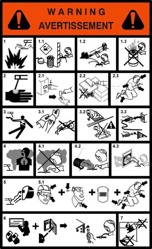
6943300030

SICUREZZE
LO SHOCK ELETTRICO PUÒ UCCIDERE                                                   WARNING
- Disconnettere la macchina dalla rete di
alimentazione prima di intervenire sul generatore.
- Non lavorare con i rivestimenti dei cavi deteriorati.
- Non toccare le parti elettriche scoperte.
- Assicurarsi che tutti i pannelli di copertura del
generatore di corrente siano ben fissati al loro posto
quando la macchina è collegata alla rete di
alimentazione.
- Isolate Voi stessi dal banco di lavoro e dal pavimento
(Ground): usate scarpe e guanti isolanti.
- Tenete guanti, scarpe, vestiti, area di lavoro, e
questa apparecchiatura puliti ed asciutti.

I CONTENITORI SOTTO PRESSIONE POSSONO
ESPLODERE SE SALDATI.
Quando si lavora con un generatore di corrente:
- non saldare contenitori sotto pressione.
- non saldare in ambienti contenenti polveri o vapori
esplosivi.

LE RADIAZIONI GENERATE DALL’ARCO Dl
SALDATURA POSSONO DANNEGGIARE GLI
OCCHI E PROVOCARE BRUCIATURE ALLA
PELLE.
- Proteggere gli occhi ed il corpo adeguatamente.
- È indispensabile per i portatori di lenti a contatto
proteggersi con apposite lenti e maschere.

PREVENZIONE USTIONI
Per proteggere gli occhi e la pelle dalle bruciature e        PREVENZIONE INCENDI
dai raggi ultravioletti:                                      La saldatura produce schizzi di metallo fuso.
- portare occhiali scuri. Indossare vestiti, guanti e         Prendere le seguenti precauzioni per evitare incendi:
scarpe adeguate.                                              - assicurarsi un estintore nell’area di saldatura.
- usare maschere con i lati chiusi, aventi lenti e vetri di   - allontanare il materiale infiammabile dalla zona
protezione a norme (grado di protezione DIN 10).              immediatamente vicina all’area di saldatura.
- avvisare le persone circostanti di non guardare             - raffreddare il materiale saldato o lasciarlo raffreddare
direttamente l’arco.                                          prima di toccarlo o di metterlo a contatto con materiale
                                                              combustibile
IL RUMORE PUÒ’ DANNEGGIARE L’UDITO.                           - non usare mai la macchina per saldare contenitori di
- Proteggersi adeguatamente per evitare danni.                materiale potenzialmente infiammabile. Questi
                                                              contenitori devono essere puliti completamente prima
I FUMI ED I GAS POSSONO DANNEGGIARE LA                        di procedere alla saldatura.
VOSTRA SALUTE.                                                - ventilare l’area potenzialmente infiammabile prima di
- Tenere il capo fuori dalla portata dei fumi.                usare la macchina.
- Provvedere per una ventilazione adeguata dell’area          - non usare la macchina in atmosfere che contengano
di lavoro.                                                    concentrazioni elevate di polveri, gas infiammabili o
- Se la ventilazione non è sufficiente, usare un              vapori combustibili.
aspiratore che aspiri dal basso.
                                                              PREVENZIONE CONTRO SHOCK ELETTRICI
IL CALORE, GLI SCHIZZI DEL METALLO FUSO E                     Prendere le seguenti precauzioni quando si opera con
LE SCINTILLE POSSONO PROVOCARE INCENDI.                       un generatore di corrente:
- Non saldare vicino a materiali infiammabili.                - tenere puliti se stessi ed i propri vestiti.
- Evitare di portare con sé qualsiasi tipo di                 - non essere a contatto con parti umide e bagnate
combustibile come accendini o fiammiferi.                     quando si opera con il generatore.
- L’arco di saldatura può provocare bruciature. Tenere        - mantenere un isolamento adeguato contro gli shock
la punta dell’elettrodo lontano dal proprio corpo e da        elettrici. Se l’operatore deve lavorare in ambiente
quello degli altri.                                           umido, dovrà usare estrema cautela, vestire scarpe e
                                                              guanti isolanti.

                                                                                                                      3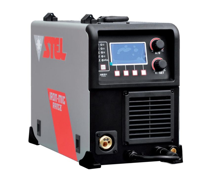
6943300030

- controllare spesso il cavo di alimentazione della
macchina: dovrà essere privo di danni all’isolante. I
                                                                RICEVIMENTO
CAVI SCOPERTI SONO PERICOLOSI                                   L’imballo contiene:
Non usare la macchina con un cavo di alimentazione              - N. 1 generatore
danneggiato;          è       necessario     sostituirlo        - N. 1 manuale istruzione
immediatamente.                                                 - N. 1 Kit messa in servizio
- se c’è la necessità di aprire la macchina, prima              Verificare che siano compresi nell’imballo tutti i
staccare l’alimentazione. Aspettare 5 minuti per                materiali sopra elencati. Avvisare il Vs. distributore se
permettere ai condensatori di scaricarsi. Non                   manca qualcosa. Verificare che il generatore non sia
rispettare questa procedura può esporre l’operatore a           stato danneggiato durante il trasporto. Se vi è un
pericolosi rischi di shock elettrico.                           danno evidente, vedere la sezione RECLAMI per
- non operare mai con il generatore, se la copertura di         istruzioni. Prima di operare con il generatore leggere
protezione non è al suo posto.                                  attentamente questo manuale di istruzioni.
- assicurarsi che la connessione di terra del cavo di
alimentazione, sia perfettamente efficiente.                    RECLAMI
                                                                Reclami per danneggiamento durante il trasporto:
Questo generatore è stato progettato per essere                 Se la Vs. apparecchiatura viene danneggiata durante
utilizzato in ambiente professionale ed industriale. Per        la spedizione, dovete inoltrare un reclamo al Vs.
altri tipi di applicazione contattare il costruttore. Nel       spedizioniere.
caso in cui disturbi elettromagnetici siano                     Reclami      per   merce     difettosa:      Tutte    le
individuati è responsabilità dell’utilizzatore della            apparecchiature spedite da STEL sono state
macchina risolvere la situazione con l’assistenza               sottoposte ad un rigoroso controllo di qualità. Tuttavia
tecnica del costruttore. È vietato l’utilizzo e                 se la Vs. apparecchiatura non dovesse funzionare
l’avvicinamento alla macchina da parte di persone               correttamente, rivolgetevi al Vs. concessionario
portatori di stimolatori elettrici (PACE MAKERS).               autorizzato.

DESCRIZIONE GENERALE
Questa nuova serie di generatori a regolazione
elettronica     governata      da    microprocessore            DATI TECNICI
,consente di raggiungere una eccellente qualità di
saldatura, grazie alle avanzate tecnologie
applicate. Il circuito microprocessore controlla ed         A
ottimizza        il      trasferimento        dell’arco
indipendentemente dalla variazione del carico e
dell’impedenza dei cavi di saldatura.
I comandi sul pannello frontale consentono una
facile programmazione delle sequenze di saldatura
                                                            B
in funzione delle esigenze operative.
La tecnologia inverter usata ha permesso di
ottenere:
- generatori con peso e dimensioni estremamente
contenuti;
- ridotto consumo energetico;
- eccellente risposta dinamica;
- fattore di potenza e rendimenti molto alti;
- caratteristiche di saldatura migliori;
- visualizzazione su display dei dati e delle funzioni
impostate.
I componenti elettronici sono racchiusi in una              C
robusta carpenteria facilmente trasportabile e
raffreddati ad aria forzata con ventilatori a basso         D
livello di rumorosità.

N.B. Il generatore non è adatto per sgelare tubi.

                                                                                                                       4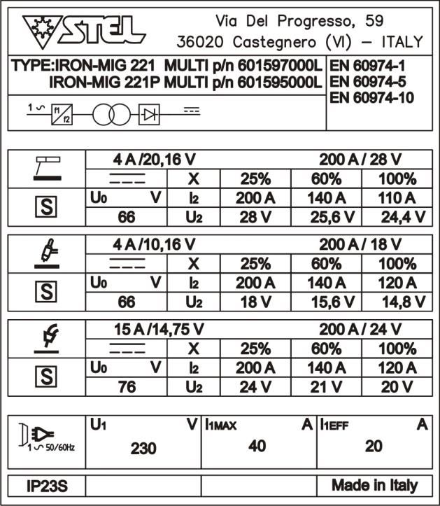
6943300030

                                                       potenza elettrica e’ fornita dal sistema pubblico di
A                                                      alimentazione a bassa tensione. Ci possono
                                                       essere potenziali difficoltà a garantire la
                                                       compatibilità elettromagnetica di questi ambienti a
                                                       causa di disturbi condotti e irradiati.
                                                       Il generatore IRON MIG 221/221P non rispetta i
B                                                      limiti della IEC 61000-3-12.
                                                       Se collegato alla rete BT industriale pubblica è
                                                       responsabilità dell'installatore o dell'utilizzatore
                                                       assicurarsi,      previa    consultazione     dell'Ente
                                                       distributore, se lo stesso è collegabile.
                                                       Il buon funzionamento del generatore è assicurato da
                                                       un’ adeguata installazione; è necessario quindi:
                                                       - Sistemare la macchina in modo che non sia
                                                       compromessa la circolazione d’ aria assicurata dal
                                                       ventilatore interno .
                                                       - Evitare che i ventilatori immettano nella macchina
                                                       depositi o polveri.
C                                                      - E’ bene evitare urti, sfregamenti, ed in maniera
                                                       assoluta l’ esposizione a stillicidi, fonti di calore
D                                                      eccessive, o comunque situazioni anomale.

                                                       TENSIONE DI RETE
A) IDENTIFICAZIONE                                     Il generatore funziona per tensioni di rete che si
Nome, indirizzo del costruttore                        discostano fino al +/- 15% dal valore nominale
Tipo generatore                                        (Tensione nominale 230V, tensione minima 195V,
Identificazione riferita al numero di serie            tensione massima 265V).
Simbolo del tipo di generatore                         Iron Mig 221/221P MULTI                   Fuse 20A
Riferimento alla normativa di costruzione              Iron Mig 221/221P MULTI 16A               Fuse 16A
B) DATI DISALDATURA
Simbolo del processo di lavoro                         COLLEGAMENTO
Simbolo per generatori idonei ad operare in ambiente   - Prima di effettuare connessioni elettriche tra il
a rischio accresciuto di scossa elettrica.             generatore di corrente e l’ interruttore di linea,
Simbolo della corrente                                 accertarsi che quest’ ultimo sia aperto.
Tensione assegnata a vuoto (tensione media)            - Il quadro di distribuzione deve essere conforme alle
Gamma della corrente                                   normative vigenti nel paese di utilizzo.
Valori del ciclo di intermittenza (su 10 minuti)       -L’ impianto di rete deve essere di tipo industriale.
Valori della corrente assegnata                        -Predisporre una apposita presa che preveda
Valori della tensione convenzionale a carico           l’alloggiamento dei conduttori del cavo di
                                                       alimentazione.
C) ALIMENTAZIONE                                       -Per i cavi più lunghi maggiorare opportunamente la
Simbolo per l’alimentazione (numero fasi e             sezione del conduttore.
frequenza)                                             -A monte, l’apposita presa di rete dovrà avere un
Tensione assegnata di alimentazione                    adeguato interruttore munito di fusibili ritardati.
Massima corrente di alimentazione                      MESSA A TERRA
Massima corrente efficace di alimentazione             - Per la protezione degli utenti il generatore dovrà
(identifica il fusibile di linea)                      essere assolutamente collegato correttamente
                                                       all’impianto di terra (NORMATIVE INTERNAZIONALI
D) ALTRE CARATTERISTICHE                               DI SICUREZZA).
Grado di protezione.                                   - E’ indispensabile predisporre una buona messa a
                                                       terra tramite il conduttore giallo-verde del cavo di
IRON MIG 221 MULTI – IRON MIG 221 P MULTI              alimentazione, onde evitare scariche dovute a contatti
                                                       accidentali con oggetti messi a terra.
Efficienza          MMA              89%               Lo chassis (che è conduttivo) è connesso
Potenza a vuoto     MMA              15 W              elettricamente con il conduttore di terra; non collegare
                                                       correttamente a terra l’ apparecchiatura può provocare
                                                       shock elettrici pericolosi per l’utente, e un non corretto
INSTALLAZIONE                                          funzionamento del generatore.
ATTENZIONE:
Questa apparecchiatura in CLASSE A non e’
destinata all’uso in ambienti residenziali dove la

                                                                                                               5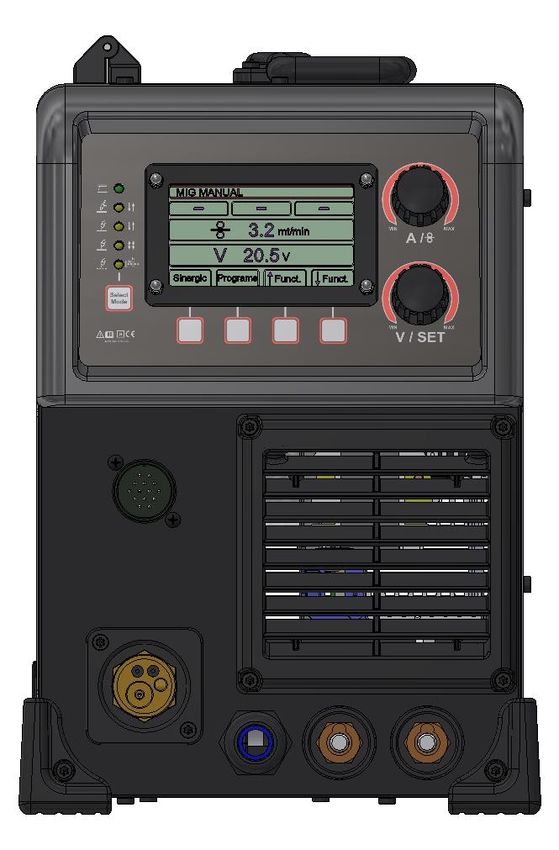
6943300030

                                                      11   Encoder regolazione tensione / altre
SOLLEVAMENTO                                               funzioni V/SET ;
ATTENZIONE                                            12   Encoder regolazione corrente / Velocità del
                                                           filo A/Vel.;
Il generatore pesa 19,5 Kg / 43 lb                    13   Display digitale.
Il generatore+bobina da 5Kg pesa 24,5 Kg / 54 lb
Il generatore+bobina da 15Kg pesa 34,5 Kg / 76 lb
                                                      DESCRIZIONE SCHERMATA
                                                      PRINCIPALE MODALITA’
                                                      SINERGICA

SOLLEVAMENTO MANUALE
E' possibile il sollevamento manuale del
generatore senza bobina o con bobina montata da
5Kg.
ATTENZIONE! non sollevare individualmente il
generatore con bobina montata da 15Kg.
Prima di sollevare il generatore togliere la bobina
da 15 Kg.

AVVERTENZA
POSIZIONAMENTO
PRECARIO                                              14   Indicazione Programma Sinergico Scelto
Se il generatore cade può causare infortuni.          15   Indicazione Corrente di saldatura
Non mettere in funzione o spostare il generatore      16   Indicazione Velocità Filo
nel caso si trovi in posizione precaria.              17   Indicazione Bilanciamento Tensione Sinergia
Non posizionare il generatore su piani inclinati      18   Indicazione Modalità Sinergico/Manuale
superiori a 10°.                                      19   Indicazione Job Mode
                                                      20   -
                                                      21   Indicazione Selezione Funzioni
DESCRIZIONE PANNELLO                                  22   Indicazione Spessore Materiale
FRONTALE                                              23   Indicazione Tensione Sinergica

1      Led modalità saldatura ELETTRODO;
2      Led modalità saldatura TIG LIFT;
3      Led modalità saldatura MIG 2T;
4      Led modalità saldatura MIG 4T;
5      Led modalità MULTI SPOT/PUNTATURA;
6      Pulsante Select Mode;
7      Pulsante Selezione Funzioni;
8      Pulsante Selezione Funzioni;
9      Pulsante Selezione Funzioni;
10     Pulsante Selezione Funzioni;

                                                                                                     6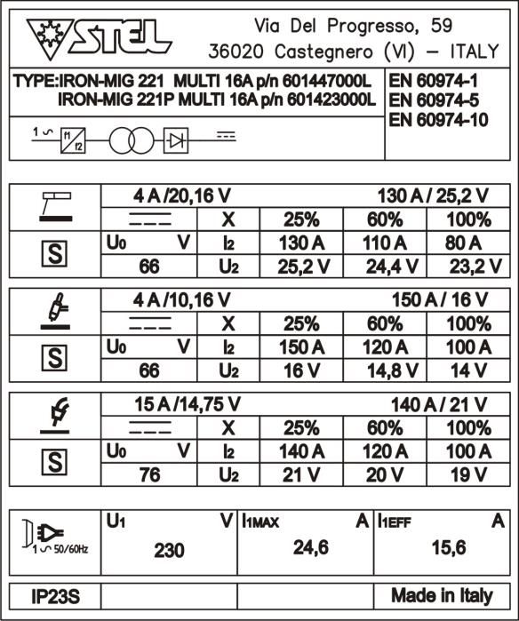
6943300030

                                                        3) Collegare la torcia TIG alla pres centralizzata
DISPOSIZIONE SALDATURA                                  della macchina polarità negativa ( - );
AD ELETTRODO                                            4) Allacciare la bombola del gas all’apposito
1)      Rispettare        le    indicazioni  fornite    raccordo posto sul pannello posteriore della
precedentemente a riguardo dell’allacciamento           macchina;
primario e dell’installazione;                          5) Premere il pulsante Select Mode (rif.6) fino a
2) Collegare il cavo di massa alla presa dinse.         selezionare     la     modalità     TIG,    indicata
Polarita’ negativa ( - );                               dall’accensione del rispettivo LED (rif.2);
3) Collegare la pinza porta elettrodo alla presa        6) Impostare la corrente di saldatura con l’encoder
della macchina polarità positiva ( + );                 di regolazione A/Vel. (rif.12);
4) Inserire l’anima scoperta dell’elettrodo nella       7) Procedere con la saldatura.
pinza porta elettrodi;
5) Premere il pulsante Select Mode (rif.6) fino a
selezionare la modalità ELETTRODO, indicata
dall’accensione del rispettivo LED (rif.1);
6) Impostare la corrente di saldatura con l’encoder
di regolazione A/Vel. (rif.12);
7) Procedere con la saldatura.

V.R.D. (SOLO IN MODALITA’ ELETTRODO)
La sigla V.R.D. sta per VOLTAGE REDUCTION
DEVICE che non è altro che un sistema per la
riduzione della tensione a vuoto. Quando si installa
il V.R.D. in una saldatrice esso riduce la tensione a
vuoto massima ad una tensione di sicurezza che          DISPOSIZIONE
normalmente è al di sotto dei 18V.                      SALDATURA MIG CON GAS
     - Il V.R.D. è usato come aiuto ulteriore per la
                                                        1)      Rispettare        le   indicazioni   fornite
         sicurezza dell’operatore.
                                                        precedentemente a riguardo dell’allacciamento
     - Le procedure per la sicurezza sul lavoro
                                                        primario e dell’installazione;
         devono sempre essere seguite con
                                                        2) Collegare il cavo di massa alla presa dinse.
         attenzione.
                                                        Polarita’ negativa ( - );
                                                        3) Collegare il cavo con spina dinse che fuoriesce
ATTIVAZIONE DEL V.R.D.
                                                        dalla macchina alla boccola positiva della stessa
1) Accendere il generatore,
                                                        macchina( + );
2) Tener premuto il pulsante Select Mode (rif.6)
                                                        4) Collegare la torcia MIG alla presa centralizzata
per circa 4 secondi, rilasciare poi il pulsante; il
                                                        con polarità positiva ( + ).
LED modalità elettrodo (rif.1) lampeggia,
                                                        5) Allacciare la bombola del gas all’apposito
(FUNZIONE V.R.D. INSERITA Vout 18V). La
                                                        raccordo posto sul pannello posteriore della
modalità VRD rimane inserita anche dopo lo
                                                        macchina;
spegnimento e la riaccensione della macchina.
                                                        6) Caricare il filo aprendo lo sportello laterale e
                                                        inserendo la bobina nell’apposito porta bobina.
ESCLUSIONE DEL V.R.D.
1) Accendere il generatore,
                                                        AVVERTENZA
2) Tenere premuto il pulsante Select Mode (rif.6)
per circa 4 secondi, rilasciare poi il pulsante; il
LED modalità elettrodo (rif.1) rimane fisso,
(FUNZIONE V.R.D. esclusa). La modalità VRD
rimane sempre esclusa anche dopo lo
spegnimento e la riaccensione della macchina.

DISPOSIZIONE                                            IL  FILO                 PER I PRIMI 4
                                                        SECONDI E’ IN TENSIONE DI SALDATURA.
SALDATURA TIG                                           NON TOCCARE IL FILO E GLI ORGANI DI
1)      Rispettare        le   indicazioni  fornite     TRASMISSIONE.
precedentemente a riguardo dell’allacciamento
primario e dell’installazione;                          Inserire il filo nel trainafilo facendolo aderire alla
2) Collegare il cavo di massa alla presa dinse.         gola del rullo (ATTENZIONE: il rullo ha due gole
Polarita’ positiva ( + );                               perché girandolo è possibile usarlo per un altro
3) Collegare il cavo con spina dinse che fuoriesce      diametro       di   filo.   Vedi    paragrafo    Rolls
dalla macchina alla boccola negativa della stessa       Specifications). Quando si cambia la sezione del
macchina( - );                                          filo è necessario cambiare: rullo e tubetto

                                                                                                            7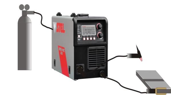
6943300030

portacorrente (è la parte terminale della torcia da       AVVERTENZA
cui si vede spuntare il filo).
Svitare la terminazione esterna della torcia (ugello)                             WARNING
e il tubetto portacorrente per facilitare il passaggio                          AVVERTENZA
del filo. Srotolare il cavo della torcia in modo da far                        AVERTISSEMENT
                                                                                 WARNUNG
fare al filo meno curve possibile. Inserire la spina in                         ADVERTENCIA
una presa di corrente adeguata ( vedi capitolo            DISPOSIZIONE SALDATURA
                                                                PRIMA DI INIZIARE LA SALDATURA
allacciamento). Chiudere il rullo pressore,                         CHIUDERE IL PORTELLO

accendere la macchina portando l’interruttore di          MIG NO GAS
                                                                TO OPERATE CLOSE THIS PANEL

linea in posizione “ON”. Premere il pulsante torcia       Per AVANT  D’UTILISER LE GENERATEUR, IL
                                                                l'impiego     di CE
                                                                    FAUT FERMER   unPANNEAU
                                                                                       filo animato speciale che
per far girare il motore del traino fino alla             prevede
                                                               VOR DEMuna    saldatura
                                                                        SCHWEISSEN         senza impiego di gas,
                                                                                     DEN DECKEL
                                                                          SCHLIESSEN
fuoriuscita del filo dalla torcia. Spegnere la            procedere in questo       modo:
                                                             PARA UTILIZAR LA MAQUINA, CIERRE ESTE
macchina portando l’interruttore di linea in              1)       RispettarePANEL    le      indicazioni  fornite
posizione “OFF”.                                          precedentemente a riguardo dell’allacciamento
Riavvitare il tubetto portacorrente e l'ugello.           primario e dell’installazione;
Regolare la frizione del trainafilo (una regolazione      2) Collegare il cavo di massa alla presa dinse.
più accurata sarà possibile dopo alcune prove).           Polarita’ positiva ( + );
                                                          3) Collegare il cavo con spina dinse che fuoriesce
7) Premere il pulsante Select Mode (rif.6) fino a         dalla macchina alla boccola negativa della stessa
selezionare la modalità MIG desiderata, indicata          macchina( - );
dall’accensione del rispettivo LED (rif.3,4,5). Le        4) Collegare la torcia MIG alla presa centralizzata
modlaità disponibili sono le seguenti:                    euro polarità negativa ( - ).
MIG 2 TEMPI: in questa modalità l’arco di
saldatura si innesca quando il filo va a contatto con     Ora procedere come dal punto 5 della saldatura
il pezzo. Nel momento in cui si preme il pulsante         MIG con gas.
torcia il filo comincia ad uscire e si ferma quando si
rilascia il pulsante.                                     DISPOSIZIONE
MIG 4 TEMPI: Nel momento in cui si preme il
pulsante torcia si ha la fuoriuscita di gas (pre-gas)     SALDATURA MIG SINERGICO
Quando il pulsante torcia viene rilasciato il filo        1)Seguire fino al punto 7 le disposizioni di
comincia ad uscire, va a contatto con il pezzo e si       saldatura MIG con o senza gas;
innesca l’arco di saldatura. Premendo nuovamente          2)Per impostare la saldatura in modalità sinergica
il pulsante si spegne l’arco e il gas continua ad         premere il pulsante SIN/MAN ( rif. 7)
uscire per tutto il tempo in cui rimane premuto il        3) A questo punto tramite i pulsanti ↑ (rif.9) e ↓
pulsante. Al momento del rilascio del pulsante            (rif.10) evidenziare il programma sinergico
inizia il post-gas precedentemente impostato.             desiderato e premere il pulsante SELECT (rif.7)
MULTI SPOT: In questa modalità viene impostato            per accedere alla schermata delle regolazioni di
un tempo di ON e un tempo di OFF. Mantenendo il           saldatura del programma sinergico scelto
pulsante torcia premuto automaticamente viene
gestito il tempo di arco acceso e il tempo di arco
spento. Impostando a 0 il tempo di OFF la
macchina esegue un solo punto per poi fermarsi
(PUNTATURA).

Ora in caso si volesse procedere con la
saldatura in modalità manuale procedere come
descritto in seguito, altrimenti vedere il
capitolo “DISPOSIZIONE SALDATURA MIG
SINERGICO”.                                               REGOLAZIONE VELOCITÀ DI ACCOSTAMENTO
                                                          (START SPEED)
8)Impostare la velocità del filo con l’encoder di         Premere il pulsante SETUP (rif.10) per entrare
regolazione A/Vel. (rif.13);                              nella schermata MIG START PARAMETERS
9)Impostare la tensione di saldatura con l’encoder        SETTING.
di regolazione V/SET (rif.12);                            Per impostare il valore di START SPEED regolare
10) Procedere con la saldatura.                           l’ encoder V/SET (rif.11). Il valore di START
                                                          SPEED è regolabile dal 15 al 135 % della velocità
                                                          di saldatura impostata .

                                                          REGOLAZIONE TEMPO RAMPA DI INNESCO
                                                          (START TIME)
                                                          Premere il pulsante SETUP (rif.10) per entrare

                                                                                                                8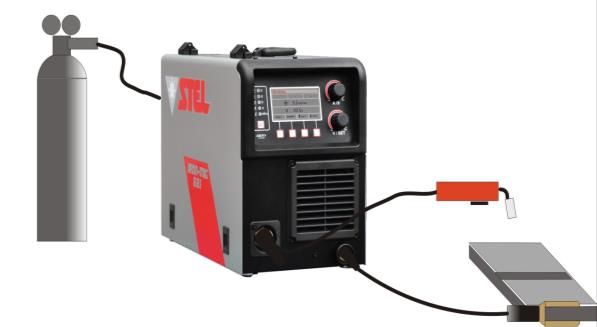
6943300030

nella schermata MIG START PARAMETERS                    Se ciò avviene sul display la velocità del filo verrà
SETTING. Premere il pulsante SELECT (rif.7) per         visualizzata nel seguente modo :
selezione START TIME.                                       - Parametri di saldatura più bassi .
Per impostare il valore di START TIME regolare l’           - Il simbolo della velocità del filo diventa
encoder V/SET (rif.11). Il valore di START TIME è                color magenta.
regolabile da 0,1 a 2 secondi.                              - Il valore della velocità del filo lampeggia
                                                                 cambiando colore.
                                                        L’operatore deve reimpostare la velocità del filo
FUNZIONAMENTO START SPEED E START
                                                        con valori inferiori rispetto a quelli che hanno
TIME ( 2-4 tempi NO ALLUMINIO )
                                                        portato in protezione la macchina

                                                        INVERSIONE POLARITA’
                                                        Per la saldatura MMA :
                                                        collegare il cavo di massa alla presa - ( NEGATIVO )
                                                        collegare la pinza portaelettrodo alla presa + (
                                                        POSITIVO)

                                                        Per la saldatura TIG e MIG NO GAS:
                                                        collegare il cavo di massa alla presa + ( POSITIVO )
                                                        collegare il cavo EURO (Torcia) alla presa - (
                                                        NEGATIVO)

                                                        Per la saldatura MIG :
                                                        collegare il cavo di massa alla presa - ( NEGATIVO)
FUNZIONAMENTO START SPEED E START                       collegare il cavo EURO (Torcia) alla presa + (
TIME ( 2 tempi ALLUMINIO )                              Positivo)

                                                        PAW™
                                                        (PRECISION ALUMINIUM WELDING)
                                                        Nuovo processo di saldatura studiato da Stel
                                                        appositamente per la saldatura di lamiere di
                                                        alluminio sottili da 0,8mm a 2mm di spessore.

                                                        PRERISCALDO
                                                        Per spessori di lamiere di alluminio di 8mm è
                                                        consigliato un preriscaldo del materiale.

INDICAZIONI SALDATURA                                   FUNZIONE
                                                        MEMORIZZAZIONE E
                                                        RICHIAMO PARAMETRI DI
ALLUMINIO                                               SALDATURA (JOB MODE)
Per la saldatura dell’alluminio è necessario            Funzione attiva per tutte le modalità di saldatura
equipaggiarsi del KIT SALDATURA ALLUMINIO               Questa funzione permette di memorizzare e di
codice 601391000L. Il kit comprende :                   richiamare in qualsiasi momento tutte le
    - una guaina in grafite.                            impostazioni effettuate sul generatore. E’ possibile
    - una conf. punte guidafilo Ø 1 mm Cu Cr Zr.        salvare 29 parametri (impostazioni) di saldatura.
    - un rullo per alluminio Ø 1 – 1.2 mm . ( Vedi
        paragrafo Rolls Specifications )                MEMORIZZAZIONE PROGRAMMI DI
    -                                                   SALDATURA
                                                        1) Premere il pulsante JOB LIST (rif.8) per entrare
PROTEZIONE PER                                          nella schermata JOB LIST.
SOVRACORRENTE                                           2) Attraverso i pulsanti ↑ (rif.9) e ↓ (rif.10) o
                                                        l’encoder V/SET (rif.11) scegliere la posizione dove
Se la corrente di saldatura dovesse superare i 220      salvare il parametro di saldatura.
Ampere interviene una protezione che abbassa            3) Per salvare il parametro premere il pulsante
automaticamente la velocità del filo e i parametri di   SAVE (rif.8) e tenerlo premuto per circa 3 secondi
saldatura.                                              fino a quando si sentirà il suono del buzzer.
                                                        4)     Avvenuto      il     salvataggio     tornerete

                                                                                                           9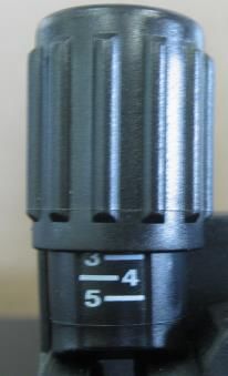
6943300030

automaticamente nella schermata principale e
potrete vedere nel riquadro JOB il numero del JOB
                                                        KIT SPOOL GUN E REMOTE
sul quale state lavorando.                              CONTROL
                                                        C’è la possibilità di collegare un REMOTE
ATTENZIONE : I PARAMETRI CHE VENGONO                    CONTROL o TORCIA SPOOLGUN come optional:
SALVATI DALLA POSIZIONE 1 ALLA 12 SONO                  Le specifiche di collegamento saranno all’interno
PROTETTI ; PERTANTO QUANDO VERRANNO                     del kit.
RICHIAMATI SARANNO BLOCCATI                             Per abilitare la funzione SPOOL GUN premere il
                                                        pulsante selezione funzioni (rif.10) per portarsi
PER USCIRE DAL BLOCCO DEI PARAMETRI E                   nella pagina MIG SETUP.
DA QUALSIASI CONDIZIONE DI JOB PREMERE                  Premere il pulsante MODIFY e tramite il pulsante
IL PULSANTE JOB LIST (rif.8) PER ENTRARE                SELECT spostare la freccia laterale nel menù
NELLA JOB LIST E PREMERE E TENER                        SPOOL GUN : ON – OFF.
PREMUTO IL PULSANTE SELECT MODE (rif.6)                 A questo punto premere il pulsante CHANGE in
PER CIRCA 5 SECONDI.                                    modo da evidenziare in giallo la scritta ON o OFF.
                                                        A questo punto premere il pulsante V (verde) per
RICHIAMO PROGRAMMI DI SALDATURA                         confermare la scelta.
MEMORIZZATI                                             Nel caso di selezione Spool Gun sulla schermata
1) Premere il pulsante JOB LIST (rif.8) per entrare     principale compare ora il simbolo della torcia
nella schermata JOB LIST.                               Spool-gun.
2) Attraverso i pulsanti ↑ (rif.9) ↓ (rif.10) o
l’encoder V/SET (rif.11) scegliere il numero del
programma da richiamare.                                IMPOSTAZIONE UNITA’ DI
3) Premere il pulsante RECALL (rif.7) e tenerlo
premuto per circa 3 secondi fino a quando si            MISURA VELOCITA’ FILO
sentirà il suono del buzzer.                            C’è la possibilità di impostare la velocità del filo in
4) Avvenuto il richiamo tornerete automaticamente       m/min o inch/min.
nella schermata principale e potrete vedere nel         Tramite il pulsante di selezione funzioni (rif.10)
riquadro JOB il numero di JOB sul quale state           portarsi nella pagina MIG SETUP. Premere il
lavorando.                                              pulsante MODIFY e con il pulsante SELECT
                                                        spostare la freccia laterale nel menù UNIT : m/min
NOTA :                                                  – ipm.
                                                        A questo punto premere il pulsante CHANGE in
il simbolo “ * “ ( asterisco ) indica il JOB in uso.
                                                        modo da evidenziare in giallo la scritta m/min o
Il simbolo “ * “ ( asterisco lampeggiante) indica che   ipm. A questo punto premere il pulsante V (verde)
si è modificato il JOB rispetto all’originale.          per confermare la scelta.
                                                        Nella schermata principale la velocità del filo sarà
                                                        riportata in ipm (minima 055 , massima 629).
FUNZIONE TRIGGER JOB                                    Anche lo spessore sarà visualizzato in inch.
Nelle prime tre posizioni della JOB LIST è possibile
attivare la funzione TRIGGER JOB.
Questa funzione permette di richiamare attraverso
una pressione veloce del pulsante torcia uno dei
primi tre parametri della JOB LIST.
I parametri per poter essere richiamati devono
avere un tempo di Pre Gas maggiore o uguale a
0,3 sec.

JOB DEMO
Dalla posizone 20 alla posizione 29 della JOB LIST
sono caricati 10 JOB DEMO . I JOB DEMO sono
dei parametri di saldatura ottenuti con diversi
programmi sinergici che possono aiutare
l’operatore.
Per avere maggiori informazioni su questi JOB
DEMO consultare tabella alla fine del manuale.

                                                                                                            10
6943300030
0,00V
DESCRIZIONE SCHERMATE I=57 A
MIG SETUP V=16,3V
Spessore=1mm
SMALTIMENTO
APPARECCHIATURE
ELETTRICHE ED
ELETTRONICHE
Non smaltire le apparecchiature
elettriche assieme ai rifiuti normali!
In ottemperanza alla Direttiva
Europea 2012/19/EU sui rifiuti da
apparecchiature elettriche ed
elettroniche e relativa attuazione
nell'ambito della legislazione nazionale, le
apparecchiature elettriche giunte a fine vita devono
essere raccolte separatamente e conferite ad un
impianto di riciclo ecocompatibile. In qualità di
proprietario delle apparecchiature dovrà informarsi
presso il nostro rappresentante in loco sui sistemi
di raccolta approvati. Dando applicazione a questa
Direttiva Europea migliorerà la situazione
ambientale e la salute umana!
RESTORE FACTORY
IN CASO DI CATTIVO FUNZIONAMENTO
DEFAULT RICHIEDETE L’ASSISTENZA DI PERSONALE
Questa funzione serve per riportare il settaggio QUALIFICATO.
della macchina ai valori di default di fabbrica.
Tramite il pulsante di selezione funzioni (rif.10) ,
portarsi nella pagina MIG-SETUP. Premere il
pulsante MODIFY e tramite il pulsante SELECT
spostare la freccia laterale nel menù RESTORE
FACTORY DEFAULT.
A questo punto premere il pulsante CHANGE.
Comparirà una schermata in cui è scritto “ DO
YOU WANT TO RESTORE FACTORY DEFAULT
DATA ?” Per ripristinare i dati di default premere il
pulsante V (verde).
La macchina automaticamente si setterà nel
seguente modo
Programma Ferro 0,8mm Sinergico
3,8 m/min
116943300030
DUTY CYCLE E
SOVRATEMPERATURA
Il ciclo di intermittenza è la percentuale di utilizzo
della saldatrice su 10 minuti che l’ operatore deve
rispettare per evitare che scatti il blocco di
erogazione per sovratemperatura.
Se la macchina entra in sovratemperatura apparirà
la seguente schermata :
Dopo 4 minuti ( necessari per il raffreddamento ) la
schermata scomparirà .
126943300030
must be free from damage to the insulation. BARE
SAFETY CABLES ARE DANGEROUS. Do not use the
ELECTRIC SHOCK CAN KILL machine if the power cable is damaged; it must be
- Disconnect the power supply before working on replaced immediately.
the welding machine. - if it is necessary to open the machine, first
- Do not work with deteriorated cable sheaths. disconnect the power supply. Wait 5 minutes to
- Do not touch bare electrical parts. allow the capacitors to discharge. Failure to take
- Ensure that all the panels covering the welding this precaution may expose the operator to
machine are firmly secured in place when the dangerous risks of electric shock.
machine is connected to the mains supply. - never work with the welding machine if the
- Insulate yourself from the work bench and from protective cover is not in place.
the floor (ground): use insulating footwear and - ensure that the earth connection of the power
gloves. supply cable is perfectly efficient.
- Keep gloves, footwear, clothes, the work area This machine has been designed for use in a
and this equipment clean and dry. professional and industrial environment. For other
types of application contact the manufacturer. If
PRESSURISED CONTAINERS CAN EXPLODE IF electromagnetic disturbances are found it is the
WELDED. responsibility of the machine user to solve the
When working with a welding machine: problem with the technical assistance of the
- do not weld pressurised containers . manufacturer.
- do not weld in environments containing explosive It is forbidden for people with PACEMAKERS to
powders or vapours. use or come near the machine.
THE RADIATIONS GENERATED BY THE
WELDING ARC CAN DAMAGE THE EYES AND
CAUSE BURNING OF THE SKIN. WARNING
- Provide suitable protection for the eyes and body.
- It is indispensable for contact lens wearers to
protect themselves with suitable lenses and
masks.
NOISE CAN DAMAGE YOUR HEARING.
- Protect yourself suitably to avoid hearing
damage.
FUMES AND GASES CAN DAMAGE YOUR
HEALTH.
- Keep your head out of the reach of fumes.
- Provide suitable ventilation of the work area.
- If the ventilation is not sufficient, use an exhaust
system that sucks from the bottom.
HEAT, SPLASHES OF MOLTEN METAL AND
SPARKS CAN CAUSE FIRES.
- Do not weld near inflammable materials.
- Avoid having any type of fuel with you such as
cigarette lighters or matches.
- The welding arc can cause burns. Keep the tip of
the electrode far from your body and from other
persons.
PREVENTION OF ELECTRIC SHOCKS
Take the following precautions when working with a
welding machine:
- keep yourself and your clothes clean.
- do not be in contact with damp or wet parts when
working with the welding machine. PREVENTION OF BURNS
- maintain suitable insulation against electric shock. To protect your eyes and skin from burns and
If the operator has to work in a damp environment, ultraviolet rays:
he must take extreme care and wear insulating - wear dark glasses. Wear suitable clothing, gloves
footwear and gloves. and footwear.
- check the machine power cable frequently: it - use masks with closed sides, having lenses and
136943300030
protective glass according to standards (degree of
protection DIN 10).
DELIVERY OF THE MATERIAL
- warn people in the vicinity not to look directly at The package contains:
the arc. - N. 1 welding machine
- N. 1 instruction manual
PREVENTION OF FIRE - N. 1 setting up kit
Welding produces splashes of molten metal. Check that all the material listed above is included
Take the following precautions to prevent fire: in the package. Inform your distributor if anything is
- ensure that there is a fire extinguisher in the missing. Check that all the material listed above is
welding area. included in the package. Inform your distributor if
- remove all inflammable material from the anything is missing. Check that the machine has
immediate vicinity of the welding area. not been damaged in transport. If you see any sign
- cool the welded material or let it cool before of damage, consult the COMPLAINTS section for
touching it or putting it in contact with combustible instructions. Before working with the machine, read
material the SAFETY and USE section of this manual.
- never use the machine for welding containers of
potentially inflammable material. These containers COMPLAINTS
must be completely cleaned before they are Complaints for damage during transport: If your
welded. equipment is damaged during transit you must
- ventilate the potentially inflammable area before present a claim to the carrier.
using the machine. Complaints for faulty goods: All the equipment
- do not use the machine in atmospheres shipped by STEL is subjected to strict quality
containing high concentrations of powders, control. However, if your equipment does not work
inflammable gases or combustible vapours. properly, consult your authorised dealer.
GENERAL TECHNICAL DATA
CHARACTERISTICS
This new series of welding machines with A
electronic regulation controlled by a
microprocessor ,allows you to achieve excellent
welding quality, thanks to the advanced
technologies applied. The microprocessor circuit
controls and optimises the transfer of the arc B
irrespective of the load variation and of the
impedance of the welding cables.
The controls on the front panel allow easy
programming of the welding sequences depending
on the operating requirements.
The inverter technology used has allowed the
following to be obtained:
- machines with extremely low weight and compact
dimensions;
- reduced energy consumption ;
- excellent dynamic response;
- very high power factor and yields; C
- better welding characteristics;
- viewing of the data and of the set functions on the D
display.
The electronic components are enclosed in a
sturdy structure that is easy to carry and cooled
with forced air by fans with low noise production.
N.B. This welding machine is not suitable for
thawing pipes.
146943300030
intended for use in residential locations where the
A electrical power is provided by the public low-
voltage supply system. There may be potential
difficulties in ensuring electromagnetic compatibility
in those locations, due to conducted as well as
radiated disturbances. This equipment does not
B comply with IEC 61000-3-12.If it is connected to a
public low voltage system, it is the responsibility of
the installer or user of the equipment to ensure, by
consultation with the distribution network operator
if necessary, that the equipment may be connected
The good operation of the machine is ensured by
correct installation; you must therefore proceed as
follows:
- Position the machine in such a way that there is
no obstacle to the air circulation ensured by the
internal fan since the internal components require
suitable cooling.
C - Ensure that the fan does not send deposits or
dust into the machine.
D - Avoid impacts, rubbing, and – absolutely no
exposure to dripping water, excessive heat
sources, or any abnormal situations.
A) IDENTIFICATION
Name, address of the manufacturer MAINS VOLTAGE
Type of welding machine The machine operates from a mains voltages
Identification with reference to serial number differing by +/- 15% from the rated mains value
Symbol of the type of welding machine (example: 230V rated, Minimum voltage 195V,
Reference to the construction standards maximum voltage 265V).
IronMig 221/221P MULTI Fuse 20A
B) WELDING OUTPUT IronMig 221/221P MULTI 16A Fuse 16A
Symbol of the work process
Symbol for welding machines suitable for working in CONNECTION
an environment with a high risk of electric shock. - Before making the electrical connections between
Symbol of the welding current the welding machine and the line switch, ensure
Assigned no-load voltage (operating voltage) that the switch is turned off .
Range of the welding current - The distribution panel must comply with the
Values of the intermittence cycle (in 10 minutes) regulations in force in the country of use.
Values of the assigned welding current - The mains system must be of the industrial type.
Values of the conventional loaded voltage - For longer connecting cables, increase the lead
C) POWER SUPPLY section as required.
Power supply symbol (number of phases and - When using long extension cables, the cable core
frequency) diameter size is relevant to the machine
Assigned power supply voltage requirements for achieving optimum performance.
Maximum power supply current - The power input supply socket from the mains
Maximum effective power supply current (identifies voltage supply, must have a suitable switch
the line fuse) provided together with a 'slow-burning' type
fuse(s).
D) OTHER CHARACTERISTICS - In the event of damage to the power cable,
Degree of protection . replacement or repair must be performed by a
qualified person at an approved service centre.
IRON MIG 221 MULTI – IRON MIG 221 P MULTI
EARTHING
Efficiency MMA 89% - To ensure user protection the welding machine
Idle state power MMA 15 W must absolutely be correctly connected to the earth
consuption system (INTERNATIONAL SAFETY
REGULATIONS).
- It is indispensable to provide good earthing by
INSTALLATION means of the yellow-green lead in the power cable,
INSTALLATION in order to avoid discharges due to accidental
WARNING: This Class A equipment is not contacts with earthed objects .
- The chassis (which is conductive) is electrically
156943300030
connected with the earth lead; if the equipment is 13 Digital Display
not suitably connected to earth it may cause
electric shocks which are dangerous for the user.
LIFTING
WARNING: SYNERGIC MODE MAIN
The machine weights 19,5 Kg / 43lb
The machine+ 5 Kg Spool weights 24,5 Kg / 54 lb
PAGE DESCRIPTION
The machine+15 Kg Spool weights 34,5 Kg / 76 lb
Lifting by hand:
It is possible lifting the generator by hand without
spool or with 5 kg spool.
ATTENTION! No lifting the generator with 15 Kg
spool by himself .
Before lifting the generator take out the 15 Kg
spool.
14 Synergic Program chosen indication
15 Welding current indication
INSTRUCTION FOR 16 Wire Speed indication
INSECURE POSITIONING 17 Synergic Voltage Adjustment indication
Failure to properly secure the machine can cause 18 Synergic/Manual mode indication
personal injury. If machine is in an insecure 19 Job Mode indication
position do not attempt to switch on. Do not put the 20 -
machine on an unlevelled surface greater than 10°. 21 Multi-Functions selection
22 Thickness Material selection
FRONT PANEL DESCRIPTION 23 Synergic Voltage indication
PREPARING FOR
ELECTRODE WELDING
1) Respect the indications given previously
concerning primary connection and installation.
2) Connect the earth cable to the socket of the
machine. Negative polarity ( - )
3) Connect the electrode holder to the socket of
the machine. Positive polarity (+ );
4) Insert the bare core of the electrode in the gun;
5) Press the Select Mode (ref.6) button to select
the ELECTRODE mode, indicated by the LED
1 ELECTRODE led indicating mode; (ref.1);
2 TIG LIFT Led indicating mode; 6) Set the welding current with the encoder
3 MIG 2T Led indicating mode; A/W.Sp. (ref.12).
4 MIG 4T Led indicating mode; 7) Proceed with welding.
5 MULTI SPOT WELDING led indicating mode;
6 Select Mode button V.R.D. (ONLY IN MMA MODE)
7 Function Selection button; The initials V.R.D. stand for VOLTAGE
8 Function Selection button; REDUCTION DEVICE, which is a system for
9 Function Selection button; reducing the no-load voltage (OCV). When the
10 Function Selection button; V.R.D. is installed in a welding machine it reduces
11 Encoder for Voltage regulation/ other the maximum no-load voltage to a safety voltage
Functions V/SET ; which is normally less than 18V.
12 Encoder for Wire Speed / Amps regulation - The V.R.D. is used as an additional aid for
A/ W.Sp.
166943300030
operator safety. machine to the positive socket ( + )
- The procedures for safety at work must always be 4) Connect the torch coupling to the centralised
carried out with attention. socket of the machine. Positive polarity ( + ).
5) Connect the gas cylinder to the proper coupling
ACTIVATION OF V.R.D. provided on the rear panel of the machine;
1) Switch on the welding machine; 6) Load the wire, opening the side door and fitting
2) Hold down button Select Mode (ref.6) for about the bobbin on the reel provided.
4 seconds, then release the button; the LED
indicating electrode mode start blinking (ref.1) WARNING
(V.R.D. FUNCTION ON Vout
18V). VRD mode remains activated when
switching the machine off and on again.
DEACTIVATION OF V.R.D.
1) Switch on the welding machine.;
2) Hold down button Select Mode (ref.6) for
about 4 seconds, then release the button; the LED
indicating electrode mode remains lit with a fixed WELDING WIRE AND DRIVE PARTS FOR THE
light (ref.1 (V.R.D. FUNCTION deactivated). VRD FIRST 4 SECONDS ARE AT WELDING
mode remains deactivated when switching the VOLTAGE.
machine off and on again. KEEP HANDS AWAY.
Insert the wire in the wire feeder, making it adhere
to the race of the roller (ATTENTION: the roller has
PREPARING FOR TIG two races because by turning it over it can be used
WELDING for another size of wire.Read the paragraph Rolls
Specifications ).
1) Respect the indications given previously
When changing the section of the wire it is
concerning primary connection and installation.
necessary to change the rollers and the current
2) Connect the earth cable to the socket of the
supply pipe (that is the end part of the torch from
machine. Positive polarity ( + )
which you can see the wire protruding).
3) Connect the cable that exit from the front of the
Unscrew the outside end of the torch (nozzle) and
machine to the negative socket ( - )
the current supply pipe to facilitate the passage of
4) Connect the torch coupling to the centralised
the wire.
socket of the machine. Negative polarity ( - ).
Unwind the torch cable so that the wire makes the
5) Connect the gas bottle to the connector
least possible number of curves .
provided on the rear of the generator.
Insert the plug in a suitable power socket.
6) With the Select Mode button (ref.6) to select the
Close the pressing roller, switch on the machine
TIG mode (ref.2)
turning the line switch to “ON” position, press the
7) Set the welding current with the encoder
wire advance button to make the feeding motor run
A/W.Sp. (ref.12).
until the wire comes out of the torch (keep the side
8)Proceed with welding.
door closed while performing this operation).
Switch off the machine, turning the line switch to
“OFF” position.
Screw the current supply pipe and the nozzle back
on.
Regulate the friction of the wire feeder (a more
accurate regulation will be possible after a few
tests).
7)Press the Select Mode button (ref.6) to select the
desider mode, indicated by the lighting of the
corresponding LED (ref. 3,4,5): The following mode
are available:
PREPARING FOR MIG MIG 2T : in this function the arc start when the wire
goes in contact with the piece. When you press the
WELDING WITH GAS torch button the wire start come out and it stops
1) Respect the indications given previously when you leave the button.
concerning primary connection and installation. MIG 4T : when you press the torch button the gas
2) Connect the earth cable to the socket of the comes out ( pre gas ). When you leave the button
machine. Negative polarity ( - ) the wire start come out, and goes in contact with
3) Connect the cable that exit from the front of the the piece and the arc start. Pushing again the
176943300030
button the arc stops and the gas continue flowing 2) Press the button SIN/MAN (ref.7) .
until the torch button is pressed. When you leave 3) Using the button ↑ (ref.9) ↓ (ref.10) or the
the button start the post time pre setted. encoder V/SET (ref.11) choose the desired
MULTI SPOT : in this function is possible regulate program and press the button SELECT (ref.7) to
the ARC ON time and also the ARC OFF time. access to the welding regulation screen.
Pressing and holding the torch button
automatically is managed the ARC ON time and
ARC OFF time. If Toff is 0 seconds, the machine
will weld only a single spot then stops. (SPOT)
Now, if you want to proceed with manual
welding act as described hereinafter, otherwise
see the section “PREPARATION FOR MIG
WELDING IN SYNERGIC MODE”
8) Regulate the wire speed using the encoder
A/W.Sp. (ref.12).
9) Regulate the voltage using the encoder
V/SET (ref.11).
PREPARING FOR MIG
WARNING
WELDING WITHOUT GAS
To use a special cored wire that allows welding
WARNING
AVVERTENZA
without the use of gas, proceed as follows:
AVERTISSEMENT 1) Check the position of the polarity changing
WARNUNG cable, opening the side door. Read the
ADVERTENCIA
paragraph “ REVERSE POLARITY”.
PRIMA DI INIZIARE LA SALDATURA
CHIUDERE IL PORTELLO 2) Connect the earth cable to the socket of
TO OPERATE CLOSE THIS PANEL the machine. Positive polarity ( + ) Red.
AVANT D’UTILISER LE GENERATEUR, IL 3) Connect the torch coupling to the
FAUT FERMER CE PANNEAU
VOR DEM SCHWEISSEN DEN DECKEL
centralised euro socket of the machine.
SCHLIESSEN Negative polarity ( - ) Black.
PREPARATION FOR MIG
PARA UTILIZAR LA MAQUINA, CIERRE ESTE
PANEL
Now proceed as in the instructions in the
paragraph "PREPARING FOR MIG WELDING
WITH GAS".
PREPARING FOR MIG
WELDING WITHOUT GAS APPROCH SPEED REGULATION
(START SPEED)
To use a special cored wire that allows welding
without the use of gas, proceed as follows: Press the button SETUP (ref.10) to go in the MIG
START PARAMETERS SETTING page.
1) Respect the indications given previously
concerning primary connection and installation; For setting the value of START SPEED regulate
the encoder V/SET (ref.11). The START SPEED
2) Connect the earth cable to the socket of the
value vary from 15 to 135 % of the welding wire
machine. Positive polarity ( + );
speed set up.
3) Connect the cable that exit from the front of the
machine to the negative socket ( - )
4) Connect the torch coupling to the centralised IGNITION SLOPE TIME REGULATION
socket of the machine. Negative polarity ( - ). (START TIME)
Press the button SETUP (ref.10) to go in the MIG
Now proceed as in the instructions in the START PARAMETERS SETTING page.
paragraph "PREPARING FOR MIG WELDING Press the button SELECT (rif.7) to select the
WITH GAS". START TIME.
For setting the START TIME regulate the encoder
PREPARATION FOR MIG V/SET (ref.11). The START TIME value vary from
0,1 to 2 seconds.
WELDING IN SYNERGIC
MODE
1) Respect the indications given previously
concerning primary connection and installation until
the point 7.
186943300030
START SPEED AND START TIME TIG e MIG NO GAS welding:
FUNCTIONING ( 2T-4T NO ALLUMINIUM ) connect the ground cable to the + ( POSITIVE )
connect the EURO cable (Torch) to the - (
NEGATIVE)
MIG welding:
connect the ground cable to the - ( NEGATIVE )
connect the EURO cable (Torch) to the +
(POSITIVE)
PAW™
(PRECISION ALUMINIUM WELDING)
START SPEED AND START TIME New welding process studied by Stel specially for
FUNCTIONING ( 2T ALLUMINIUM ) welding of thin aluminum sheets from 0,8mm to
2mm thick.
PRE-HEAT
For alluminium 8mm thick is recommended a pre-
heating of the material .
FUNCTION OF STORING AND
LOADING WELDING
PARAMETERS (JOB MODE)
Function active for all welding modes
ALUMINIUM WELDING This function allows you to store and load at any
ADVICE time all the settings made on the power source. It
For welding aluminium if is necessary to use the is possible to save 30 welding parameters settings)
KIT ALUMINIUM WELDING code 601391000L.
The kit is composed off : STORING WELDING SETTINGS
- graphite liner. 1) Press the button JOB LIST (ref.8) to go in the
- One set contact tips Ø 1 Cu Cr Zr. JOB LIST page.
- One aluminium roller Ø 1 – 1.2 mm . 2) Using the button ↑ (rif.9) ↓ (rif.10) or the
( Read the paragraph Rolls Specifications ). encoder V/SET (ref.11) select the number of the
programme in which you want to save the welding
PROTECTION FOR parameters.
OVERCURRENT 3) Press and hold the SAVE button (ref.8) for about
3 seconds until you will hear the sound of the
buzzer.
If the welding current is more than 220 Ampere
4) When the parameter will be saved you will come
there is a protection that automatically reduces the
back immediately on the main page and it is
wire speed and the welding parameters.
possible see on the frame JOB the JOB number
In the event the wire speed will show in the follow
you are using.
mode :
- Lower welding parameters.
ATTENTION : THE PARAMETERS SAVED FROM
- The wire speed symbol change color.
THE POSITION 1 TO 12 ARE PROTECTED; SO
- The value of wire speed flashing changing
WHEN YOU WILL RECALL THEM , THEY WILL
color.
BE BLOCKED.
The operator must set again the wire speed with a
lower parameter compare to the original parameter
TO REMOVE THE PROTECTION OF THE
that sent in protection the machine.
PARAMETER AND COME OUT FROM ANY JOB
CONDITIONS PRESS THE BUTTON JOB LIST
REVERSE POLARITY (ref.8) TO GO IN THE JOB LIST page AND
PRESS AND HOLD THE BUTTON SELECT
MMA welding: MODE (rif.6) FOR ABOUT 5 sec.
connect the ground cable to the - ( NEGATIVE )
connect the electrode holder to the + ( POSITIVE) LOADING STORED WELDING PROGRAMS
196943300030
1) Press the button JOB LIST (ref.8) to go in the
JOB LIST page.
SETTING UNIT MEASURING
2) Using the button ↑ (rif.9) ↓ (rif.10) or the WIRE SPEED
encoder V/SET (ref.11) select the number of the There is the opportunity to set the wire speed in
programme that you want recall. m/min or ipm.
3) Press and hold the RECALL button (ref.7) Press the FUNCTION SELECTION button (rif.10)
for about 3 seconds until you will hear the sound of to go in the MIG SETUP page.
the buzzer. Press the button MODIFY and with the button
4) After the recalling you will come back SELECT to select the menu UNIT : m/min – ipm.
immediately on the main page and it is possible Then press the button CHANGE to underline in
see on the frame JOB the JOB number you are yellow the word m/min or ipm.
using. Now press the button V ( green ) to confirm the
choice.
NOTE : On the main screen is possible to see the wire
The symbol “ * “ ( asterisk ) means the JOB in use. speed in ipm ( minimum 055 , maximum 629 ) .
The thickness will be also in inches .
The symbol “ * “ ( asterisk flashing ) means the
JOB is modified from the original.
TRIGGER JOB FUNCTION SCREENS DESCRIPTION
In the first three position of JOB LIST is possible to MIG SETUP
activate the TRIGGER JOB FUNCTION
This function allows to recall one of the first three
parameter of the JOB LIST with a quick pressure
of torch button.
For recall these parameters they must have a Pre
Gas time of 0,3 sec or more.
JOB DEMO
From the position 20 to 29 of the JOB LIST there
are 10 JOB DEMO. The JOB DEMO are welding
parameters obtained with different synergic
program that can help the welder.
For having more informations about the JOB
DEMO read the table at the page 36 of this
manual.
SPOOL GUN & REMOTE
CONTROL KIT
There is the possibility to connect a REMOTE
CONTROL or a SPOOL GUN TORCH like optional.
The connection specifications you will find inside
the kit.
For activate the SPOOL GUN press the
FUNCTION SELECTION button (rif.10) to go in the
MIG SETUP page.
Press the button MODIFY and with the button
SELECT to select the menu SPOOL GUN : ON –
OFF.
Then press the button CHANGE to underline in
yellow the word ON or OFF.
Now press the button V ( green ) to confirm the
choice.
If the SPOOL GUN is selected on the main screen
appears the symbol of spool gun torch.
206943300030
FACTORY DEFAULT DUTY CYCLE AND
RESTORE EXCESSES TEMPERATURE
This function is used to return the machine settings The duty cycle is the percentage of use of the
to factory defaults . welding machine within 10 minutes which the
Press the button Selection Function (rif.10) to go in operator must respect to avoid the machine
the MIG SETUP page. blocking output due to temperature being
Press the button MODIFY and with the button exceeded.
SELECT to select RESTORE FACTORY
DEFAULT.
Press the button CHANGE and on the screen you
will see written “ DO YOU WANT TO RESTORE
FACTORY DEFAULT DATA ?”
To restore the default data press the V (green
button )
The machine will set automatically in this mode :
Program Fe 0,8mm Synergic
3,8 m/min
0,00V
I=57 A
V=16,3V
Thickness=1mm
If the machine goes in overtemperature you will
DISPOSAL OF ELECTRICAL see the following message on the screen.
AND ELECTRONIC
EQUIPMENT
Do not dispose of electrical
equipment together with normal
waste! In observance of European
Directive 2012/19/EU on Waste
Electrical and Electronic Equipment
and its implementation in
accordance with national law,
electrical equipment that has reached the end of its
life must be collected separately and returned to an
environmentally compatible recycling facility. As the
owner of the equipment, you should get
information on approved collection systems from After 4 minutes ( necessary for cooling ) the message
our local representative. By applying this European vanish.
Directive you will improve the environment and
human health!
IN CASE OF MALFUNCTIONS, REQUEST
ASSISTANCE FROM QUALIFIED PERSONNEL.
216943300030
SICHERHEITSVORSCHRIFTEN VORSICHTSMASSNAHMEN UM EINEN
ELEKTROSCHOCK ZU VERHINDERN
EIN ELEKTROSCHOCK KANN TÖDLICH SEIN
Treffen Sie folgende Vorkehrungen, wenn Sie mit
- Vor Arbeiten am Gerät, Netzstecker ziehen
einem Schweißgerät arbeiten:
- Verwenden Sie keine beschädigten Kabel und
- Halten Sie sich und Ihre Kleidung sauber.
Leitungen
- Berühren Sie keine feuchten oder nassen Teile,
- Berühren Sie keine unter Spannung stehenden
wenn Sie mit dem Schweißgerät arbeiten.
elektrischen Bauteile
- Halten Sie eine ausreichende Isolation gegen
- Stellen Sie sicher, dass alle Abdeckungen fest
einen Elektroschock aufrecht. Sollte der Anwender
geschlossen sind, bevor das Gerät an das
in einer feuchten Umgebung arbeiten müssen, ist
Stromnetz angeschlossen wird.
für größte Vorsicht zu sorgen und geeignetes,
- Sorgen Sie für einen ausreichenden Selbstschutz
isolierendes Schuhwerk und Handschuhe zu
gegenüber dem Erd- bzw. Massepotential, durch
tragen.
die Verwendung von isolierendem Schuhwerk und
- Überprüfen Sie das Netzkabel regelmäßig: Es
Handschuhen.
darf keine Beschädigungen an der Isolation
- Halten Sie Handschuhe, Schuhwerk, Kleidung,
aufweisen. BLANKE KABEL SIND GEFÄHRLICH.
ihren Arbeitsplatz, sowie das Gerät samt
Benutzen Sie das Gerät nicht, wenn das Netzkabel
Ausrüstung, trocken und sauber.
beschädigt ist; es muss sofort ausgetauscht
werden.
UNTER DRUCK STEHENDE BEHÄLTER
- Sollte es notwendig sein, das Gerät zu öffnen,
KÖNNEN BEIM SCHWEISSEN EXPLODIEREN
ziehen Sie zuerst den Netzstecker. Warten Sie 5
Wenn Sie mit einem Schweißgerät arbeiten:
Minuten, damit sich die Kondensatoren entladen
- Schweißen Sie keine unter Druck stehenden
können. Die Missachtung dieser
Behälter
Vorsichtsmaßnahme setzt den Anwender einem
- Schweißen Sie nicht in Umgebungen mit
hohen Risiko aus, einen Elektroschock zu erleiden.
explosiven Stäuben oder Dämpfen
- Arbeiten Sie nie mit dem Schweißgerät, wenn die
Schutzabdeckung geschlossen ist.
DIE DURCH DEN LICHTBOGEN ERZEUGTE
- Stellen Sie sicher, dass Erdung des
STRAHLUNG KANN IHR AUGENLICHT
Stromversorgungskabels ausreichend
SCHÄDIGEN
leistungsfähig ist. Dieses Gerät wurde für den
- Sorgen Sie für ausreichende Schutzkleidung für
Einsatz in Beruf und Industrie entwickelt. Für
Augen und Körper
andere Arten der Anwendung kontaktieren Sie bitte
- Für Kontaktlinsenträger ist es absolut
den Hersteller. Werden elektromagnetische
notwendig, sich mit geeigneten Linsen und
Störungen festgestellt, liegt es in der
Schutzmasken zu schützen.
Verantwortung des Gerätebetreibers das Problem
mit Hilfe des technischen Kundendiensts des
LÄRM KANN IHR GEHÖR SCHÄDIGEN
Herstellers zu lösen. Für Personen, die einen
- Schützen Sie sich durch ausreichenden
Herzschrittmacher tragen, ist es verboten das
Gehörschutz vor Gehörschäden
Gerät zu bedienen, bzw. sich im Bereich des
Geräts aufzuhalten.
DÄMPFE UND GASE KÖNNEN IHRE
GESUNDHEIT SCHÄDIGEN
- Kopf von schädlichem Dämpfen und Gasen
fernhalten
- Sorgen Sie für eine ausreichende Belüftung des
Arbeitsbereichs
- Sollte die Belüftung nicht ausreichend sein,
benutzen Sie ein geeignetes Absauggerät,
welches von Unten absaugt.
HITZE, FLÜSSIGE METALLSPRITZER UND
FUNKEN KÖNNEN FEUER VERURSACHEN
- Schweißen Sie nicht in der Nähe von
entflammbaren Materialien
- Tragen Sie keine entflammbaren Dinge mit sich,
wie Feuerzeuge oder Streichhölzer
- Der Lichtbogen kann Brände verursachen. Halten
Sie die Spitze der Elektrode von Ihrem Körper,
sowie von Personen in Ihrer Nähe, fern.
22Puoi anche leggere