MACCHINE PER PRETRATTAMENTI - PRETREATMENT MACHINES
←
→
Trascrizione del contenuto della pagina
Se il tuo browser non visualizza correttamente la pagina, ti preghiamo di leggere il contenuto della pagina quaggiù
MACCHINE PER
PRETRATTAMENTI

PRETREATMENT
  MACHINES
GRIGLIATURA                                             X-RAKE / X-H.RAKE                                        4
  SCREENING                                               X-H.BELT                                                 6

                                                          X-ARC                                                    8

                                                          X-DRUM                                                 10

                                                          X-STEP                                                  12

                                                          S-SC / S.MINI / TS-TSC                                 14

                                                          VS-VCS                                                 18

                                                          X-SRD / X-SRD.D                                        20

                                                          X-INT.DRUM                                             22

                                                          X-BAR / X-BASKET                                       24

  COMPATTATORI GRIGLIATI                                  X-S.COMP                                               26
  SCREEN COMPACTORS                                       X-COMP                                                 28

  TRATTAMENTI COMBINATI                                   SET 1                                                  30
  COMBINED TREATMENTS                                     SET 2                                                  32

                                                          SET 3                                                  34

                                                          MINI.SET 2 / MINI.SET 3                                36

  TRATTAMENTO SABBIE                                      X-GC / X-GC.CONE                                       38
  SANDS TREATMENT                                         X-G.WASH                                               40

                                                          X-VORTEX                                               42

  APPLICAZIONI FOSSE SETTICHE                             SEP                                                    44
  SEPTIC APPLICATIONS                                     SEP 2                                                  46

  NOTE                                                                                                           48
  NOTES

Le immagini, foto, descrizioni e dimensioni riportate     The illustrations, photos, descriptions and dimensions
in questo catalogo sono puramente indicative.             in this catalog are given as an indication.
X2 Solutions S.r.l. si riserva il diritto di apportare    X2 Solutions S.r.l. reserves the right to make modifications
modifiche ai vari modelli in qualsiasi momento e senza     to its models at any time and without notice, in
darne avviso nel caso in cui sia considerato vantag-      the case it will be considered useful to improve them,
gioso o per qualsiasi altra motivazione sia costruttiva   or for any other needs, whether constructive or
che commerciale.                                          commercial.

I valori riportati nelle tabelle sono indicativi.         The values in the tables are only indicative.
X2 Solutions S.r.l. si riserva il diritto di apportare    X2 Solutions S.r.l. reserves the right to make
modifiche alle specifiche tecniche e dimensionali in        modifications to the technical and dimensional
qualsiasi momento e senza darne avviso nel caso in        specifications at any time and without notice, in the
cui sia considerato vantaggioso o per qualsiasi altra     case it will be considered useful to improve them, or for
motivazione sia costruttiva che commerciale. I valori     any other needs, whether constructive or commercial.
di portata sono anch’essi indicativi e devono essere      Flow rate values are also indicative and must be
verificati a seconda dell’applicazione.                    verified depending on the application.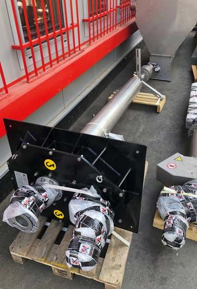
GRIGLIATURA / SCREENING

Modello / Model
                          GRIGLIA VERTICALE A BARRE
X-RAKE / X-H.RAKE         VERTICAL BAR SCREEN

                          DESCRIZIONE E FUNZIONAMENTO
                          La griglia verticale a barre risponde alla necessità di effettuare una separazione
                          grossolana dei grigliati dalle acque reflue, siano esse civili o industriali.
                          L’applicazione standard prevede l’installazione all’interno di canali costruiti in
                          cemento armato ai quali la macchina viene fissata lateralmente.
                          La macchina è formata da un telaio costruito in acciaio inox.
                          La macchina ha una superficie filtrante, con una spaziatura che può variare dai
                          6 ai 40 mm, con la quale vengono trattenuti i grigliati che hanno una dimensione
                          maggiore della spaziatura scelta, e viene lasciata passare l’acqua filtrata.
                          I grigliati sono sollevati, trasportati e scaricati tramite pettini, atti anche alla
                          pulizia della zona di filtrazione.
                          I pettini sono in acciaio inox, montati su appositi supporti in acciaio e fissati
                          direttamente ad una catena di acciaio inox.
                          Nella zona dello scarico si trova un raschiatore che ha la funzione di scaricare
                          i grigliati e di conseguenza pulire i pettini.
                          La macchina funziona comandata da un motoriduttore.
                          La parte della macchina che fuoriesce dal canale è protetta da un telaio di acciaio
                          inox.
                          La macchina può essere costruita in acciaio inossidabile.
X-RAKE                    AISI 304, in acciaio inossidabile AISI 316.

                          DESCRIPTION AND WORKING PRINCIPLE
                          The vertical bar screen meets the need to have a separation of the coarse screenings
                          from wastewater, whether civil or industrial.
                          The standard application involves the installation inside of channels constructed
                          in reinforced concrete, to which the machine is laterally fixed.
                          The machine is composed by a bearing structure made of stainless steel.
                          The machine has a filtering surface, with a spacing which can vary from 6 to 40
                          mm, with which are retained the screenings which have a size greater than the
                          sspacing aperture chosen, while the filtered water is allowed to pass.
                           The screenings are lifted, transported and discharged using combs, that are also
                           ssuitable for cleaning the filtration area.
                            The combs are made of stainless steel mounted on special steel supports and
                            directly fixed to a chain made of stainless steel.
                            In the discharge area is located a scraper which has the function to discharge
                            the screenings and consequently clean the combs.
                            The machine runs driven by a gearmotor.
                            The part of the machine which comes out from the channel is protected by a
                            sstainless steel frame.
                             The machine can be made of stainless steel AISI 304, AISI 316.
X-H.RAKE

4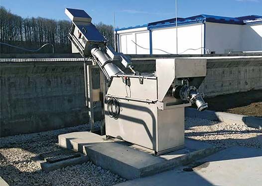
MODEL                          400       600       800      1000      1200      1400      1600      1800      2000 2200 2400 2600 2800 3000
 Channel width (Lc)             400       600       800      1000      1200      1400      1600      1800      2000 2200           2400      2600 2800 3000
 Channel height                                                                                variable
 Bars section height*
                                600       600       600       800       800       800       800       800      1300      1300      1300      1300      1300   1300
 (Hc)
 Bar dimensions                40x8      40x8      40x8      40x8      40x8      40x8      40x8      40x8 40x10 40x10 40x10 40x10 40x10 40x10
 Discharge height**
                               2300      2300      2300      2500      2500      2500      2500      2500 3000 3000 3000 3000 3000 3000
 (Hd)
* Altezza parte barrata standard, eventuali allungamenti possibili con sovrapprezzo / Standard bars section height, is possible increase it with overpriced
** Altezza di scarico standard eventuali allungamenti possibili con sovrapprezzo / Standard discharge height, is possible increase it with overpriced

                                                                                                                                                                     5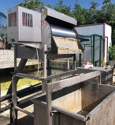
GRIGLIATURA / SCREENING

Modello / Model
                          GRIGLIA VERTICALE A TAPPETO ROTANTE
X-H.BELT                  ROTATING BELT SCREEN

                          DESCRIZIONE E FUNZIONAMENTO
                          La griglia verticale a tappeto rotante risponde alla necessità di effettuare
                          una separazione fine dei solidi dalle acque reflue, siano esse civili o industriali.
                          L’applicazione standard prevede l’installazione all’interno di canali costruiti in
                          cemento armato ai quali la macchina viene fissata lateralmente.
                          La macchina è formata da un telaio costruito in acciaio inox e da un nastro rotante
                          diviso in settori.
                          La macchina ha una superficie filtrante, con una spaziatura che può variare da
                          1 mm a 7 mm, con la quale vengono trattenuti i grigliati che hanno una dimensione
                          maggiore della spaziatura scelta, e viene lasciata passare l’acqua filtrata.
                          I solidi sono sollevati, trasportati e scaricati tramite settori forati installati su un
                          sistema di trasmissione a catena con corone di trasmissione e motoriduttore.
                          È disponibile anche una versione con dentini in materiale plastico autopulenti,
                          uniti tra loro da un alberino su ruote che va a creare un tappeto unico rotante.
                          Nella parte bassa della griglia è posizionata una spazzola in nylon fissa che svolge
                          la funzione di tenuta in corrispondenza del fondo della griglia
                          La pulizia dei settori/dentini è garantita da una spazzola rotante in materiale
                          sintetico montata sullo scarico che svolge il compito di pulizia e rimozione dei
                          solidi dagli elementi rotanti. Un sistema di lavaggio ad ugelli pulisce eventuali
                          residui rimasti attaccati al nastro.
                          I settori filtranti sono in acciaio inox, montati su appositi supporti in acciaio e
                          fissati direttamente ad una catena di acciaio inox.
                          La parte della macchina che fuoriesce dal canale è protetta da un telaio di acciaio
                          inox.
                          La costruzione del macchinario può essere eseguita in AISI 304 o AISI 316.

                          DESCRIPTION AND WORKING PRINCIPLE
                          The rotating belt screen meets the need to have a separation of fine screenings
                          from wastewater, whether civil or industrial. The standard application involves
                          the installation inside of channels constructed in reinforced concrete, to which the
                          machine is laterally fixed.
                          The machine is composed by a bearing structure made of stainless steel and a
                          rotating belt divided in sectors.
                          The machine has a filtering surface, with a spacing which can vary from 1 mm up
                          to 7 mm, that can retain the screenings that have a size greater than the spacing
                          aperture chosen, while the filtered water is allowed to pass.
                          The screenings are lifted, transported and discharged using perforated sectors,
                          installed on chain system complete with crowns and gearbox. On request is possible
                          to have the machine with a plastic self-cleaning teeth, connected together with a
                          shaft that runs on plastic wheels. This create a unit belt.
                          On the lowest part of screen is installed a nylon fixed brush that have the function of
                          sealing the bottom of the machine.
                          The s.s. sectors or plastic teeth are cleaned by a rotating nylon brush driven by
                          a gearbox mounted on the outlet of the screen. An extra nozzles bar, clean the
                          eventual solids stuck on the belt with high pressure water. The sectors are mounted
                          on special supports secured directly to a stainless steel chain.
                          The part of the machine which comes out from the channel is protected by a stainless
                          steel frame.
                          The machine can be made of stainless steel AISI 304, AISI 316.

6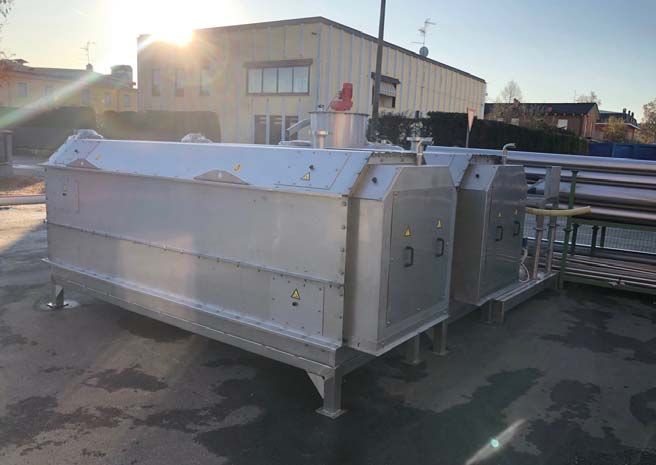
MODEL                          400       600       800      1000      1200      1400      1600      1800      2000 2200 2400 2600 2800 3000
 Channel width (Lc)             400       600       800      1000      1200      1400      1600      1800      2000 2200           2400      2600 2800 3000
 Channel height                                                                                variable
 Open area height*
                                600       600       600       800       800       800       800       800      1300      1300      1300      1300      1300   1300
 (Hc)
 Filtration                                                                                    1-8 mm
 Discharge height**
                               2300      2300      2300      2500      2500      2500      2500      2500 3000 3000 3000 3000 3000 3000
 (Hd)
* Altezza parte barrata standard, eventuali allungamenti possibili con sovrapprezzo / Standard bars section height, is possible increase it with overpriced
** Altezza di scarico standard eventuali allungamenti possibili con sovrapprezzo / Standard discharge height, is possible increase it with overpriced

                                                                                                                                                                     7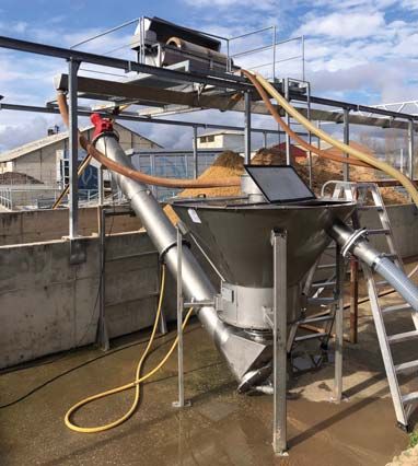
GRIGLIATURA / SCREENING

Modello / Model
                          GRIGLIA AD ARCO
X-ARC                     ARC SCREEN

                          DESCRIZIONE E FUNZIONAMENTO
                          La griglia ad arco automatica può essere installata direttamente in canali di
                          piccole-medie dimensioni, per effettuare una grigliatura grossolana.
                          Il materiale grigliato viene raccolto dai pettini di pulizia, e rotola lentamente
                          attraverso i fori. Viene quindi sollevato e depositato in un contenitore situato
                          immediatamente a valle dello schermo o rimosso attraverso un nastro trasportatore.
                          La protezione dal sovraccarico può essere costituita da dispositivi dinamometrici
                          o limitatori di corrente elettronici.

                          CARATTERISTICHE COSTRUTTIVE
                          Telaio in profilati pressopiegati o tubolari;
                          Griglia costituita da una serie di barre tagliate al plasma, di dimensioni adeguate;
                          Braccia rotanti di forma tubolare o squadrata, che vengono montate con supporti
                          al telaio portante.
                          Pettini in acciaio inox o in polizene autolubrificante, per la pulizia della zona di
                          grigliatura;
                          Lama raschiante per la pulizia automatica dei pettini, con telaio in acciaio inox e
                          profilo raschiante in polietilene, sostituibile;
                          Motoriduttore di tipo a vite senza fine
                          Spaziatura disponibile tra i 15 e i 50 mm
                          CONFIGURAZIONE STANDARD
                          Acciaio inox AISI 304/316
                          Fornibile anche in acciaio al carbonio.

                          DESCRIPTION AND WORKING PRINCIPLE
                          The screen with automatic arch can be installed directly in medium-small channels
                          for coarse screening.
                          The screened material is collected by the cleaning combs and rolls slowly through
                          the holes. It is then raised and deposited in a container situated immediately
                          downstream of the screen or removed on a conveyor belt.
                          Overload protection can consist of dynamometric devices or electronic current
                          limiters.

                          MANUFACTURING FEATURES
                          Frame made of press-formed or tubular profiles;
                          Screen consisting of a set of plasma cut bars of appropriate size;
                          Rotating comb arms in square or tubular configuration, mounted on the frame
                          with UCP supports;
                          Combs in AISI 304 stainless steel or self-lubricating polyzene that clean the screen;
                          Raping blade for automatic cleaning of the combs, with rubber buffers;
                          Worm Geared motor;
                          Spacing between 15 and 50 mm.
                          STANDARD CONFIGURATION
                          Stainless steel AISI 304/316
                          Also available in carbon steel.

8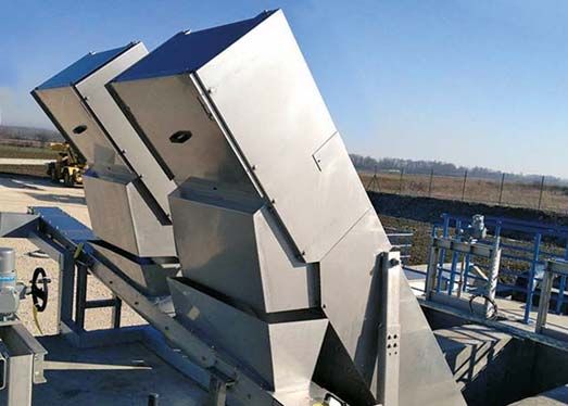
Channel Width     mm             300 - 3000
Channel Height    mm             800 - 1800
Diameter (d)      mm   1000 - 2000 - 2200 - 2500 - 3000
Max Length        mm               d + 300
Screen gaps (s)   mm                5 -50
Flow rate         m               0 - 12000
Installed power   kW              0,18 - 4,00

                                                          9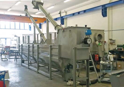
GRIGLIATURA / SCREENING

Modello / Model
                          GRIGLIA A TAMBURO ROTANTE
X-DRUM                    ROTATING DRUM SCREEN

                          DESCRIZIONE E FUNZIONAMENTO
                          La griglia a tamburo rotante esegue una microfiltrazione fine, ed è installata a
                          monte degli impianti di depurazione di piccole e medie dimensioni.
                          Il flusso incontra la superficie dello schermo a tamburo rotante perpendicolarmente
                          alla direzione del foro fra le barre. Mentre il liquido filtrato passa attraverso i fori
                          della griglia e viene scaricato in un serbatoio sotto il cilindro, i solidi sono intrappolati
                          sulla superficie dello cilindro stesso e tramite la frizione della lama scolmatrice,
                          vengono deviati ad un apposito contenitore.
                          Le barre del cilindro sono a forma di cuneo e permettendo il flusso ininterrotto di
                          pressione idraulica, riducendo al minimo il rischio di attaccamento dei solidi che
                          causano ostruzioni. La protezione contro i sovraccarichi può essere costituita
                          da dispositivi elettronici che monitorano il consumo del motore.

                          CARATTERISTICHE COSTRUTTIVE
                          Camera di alimentazione, comprensiva di troppopieno, progettata per consentire
                          alle acque reflue di coprire l’intera larghezza del cilindro grigliante;
                          Cilindro di filtrazione costituito da un particolare profilo avvolto a spirale attorno
                          a una struttura di barre longitudinali;
                          Lama scolmatrice, in materiale antiusura, che esercita una pressione costante sul
                          cilindro, con pistoni a gas idonei;
                          Sistema di controlavaggio attraverso un dispositivo installato nel cilindro filtrante;
                          Spaziatura disponibile tra i 0,25 e i 6 mm con profilo wedge wire o da 1 a 6mm
                          forato.
                          Motoriduttore di tipo a vite senza fine
                          CONFIGURAZIONE STANDARD
                          Acciaio inox AISI 304/316.

                          DESCRIPTION AND WORKING PRINCIPLE
                          The rotating drum screen executes fine micro-screening and is installed upstream
                          of small and medium-sized purification plants.
                          The flow of the suspension for screening meets the surface of the rotary screen
                          perpendicular to the direction of the hole between the bars. While the filtered
                          liquid passes through the holes of the screen and is discharged into a tank under
                          the cylinder, the solids are trapped on the surface of the same screen and are
                          drawn by rolling friction to a spillway blade that diverts them to a special container.
                          The bars of the cylinder are wedge-shaped, permitting the uninterrupted flow of
                          hydraulic pressure and minimizing the risk of solids sticking and causing obstruction.
                          Overload protection can consist of electronic devices that monitor motor consumption.

                          MANUFACTURING FEATURES
                          Feed chamber with incorporated overflow, designed to allow sewage to cover the
                          entire width of the screening cylinder;
                          Screening cylinder consisting of a particular V-shaped profile wound in a spiral
                          around a structure of longitudinal bars;
                          Spillway blade made of wear-resistant material that exerts constant pressure on
                          the cylinder with suitable gas pistons;
                          Backwash by means of a device installed in the screening cylinder;
                          Spacing between 0.25 and 6 mm wedge wire or from 1 to 6 mm perforated.
                          Worm geared motor and helical gears.
                          STANDARD CONFIGURATION
                          Stainless steel AISI 304/316.

10
MODEL 300x800 600x500 600x1000 600x1300 600x1500 900x2000 900x3000
Max height (H) mm 715 1100 1100 1100 1100 2300 2300
Max width (W) mm 615 1250 1250 1250 1250 1650 1650
Max length (L) mm 1380 1750 2550 2450 2750 3100 4100
Drum length (Lc) 800 500 1300 1200 1500 2000 3000
Drum diameter (d) 323 628 628 628 628 914 914
Inlet diameter DN 80 100 150 200 250 300 400
By pass diameter DN 80 100 150 200 250 300 400
Outlet diameter DN 100 150 200 250 300 350 500
Installed power kW 0,25 0,37 0,55 0,55 0,75 1,1 1,5
* Data referred to the compact machine
FLOWRATE**
APERTURE 0,25 0,50 0,75 1,00 2 3,00 5,00 6,00
MODEL
500 35 60 90 110 165 200 240 250
1000 70 125 170 200 330 400 480 500
1200 80 140 180 240 350 400 480 520
1500 100 200 250 320 500 600 680 730
2000 140 250 330 420 620 750 900 1000
3000 310 550 700 950 1390 1650 2000 2100
** Valori di portata relativi a profilo wedge wire / Data referred wedge wire profile
11GRIGLIATURA / SCREENING
Modello / Model
GRIGLIA A GRADINI
X-STEP STEP SCREEN
DESCRIZIONE E FUNZIONAMENTO
La griglia a gradini è una griglia con pulizia meccanica, ideale per lavori in ingresso in
impianti di depurazione, stazioni di pompaggio e in strutture di ingresso dell’acqua.
È costituita da un telaio in acciaio inox provvisto di una superficie filtrante
composta da lamelle fisse e mobili.
La distanza tra le lamelle fisse e mobili compongono la sezione filtrante.
Il telaio è installato nel canale con un angolo di inclinazione solitamente di 55°;
Il refluo passa attraverso l’area di filtrazione (lamelle) e i grigliati vengono catturati
e sollevati da una catena. I grigliati vengono poi rimossi dalla zona di filtrazione e
scaricati.
CARATTERISTICHE COSTRUTTIVE
Telaio in Acciaio Inox AISI 304 o AISI 316
Potenza installata tra i 0,55 e i 2,2 kW
Spaziatura disponibile: 3 o 6 mm
Catena in acciaio zincato o in acciaio Inox
AISI 304 o AISI 316
Lamelle in Acciaio Inox AISI 304 o AISI 316
Velocità 6m/min
Larghezza canale: da 400 mm ai 2.000 mm
Inclinazione standard: 55°
DESCRIPTION AND WORKING PRINCIPLE
The step screen is a mechanically cleaned screen that is ideal for inlet works of
treatment plants, pumping stations and water inlet structures.
It consists of a stainless steel frame provided with a fil-tration area composed by
fix and mobile lamellas. The distance between fix and mobile lamellas represents
the screen meshes section;
The frame is installed in the channel with an in-clination angle usually 55°;
wastewater passes through filtration area (lamellas) and screenings are captured
and lifted up by a chain.
Screenings are removed from the filtartion area and discharged .
MANUFACTURING FEATURES
Frame: stainless steel AISI 304/316
Installed Power: 0.55÷2.2 KW
Spacing: 3 or 6 mm
Chain: Galvanized steel-stainless steel AISI 304/316
Lamellas: stainless steel AISI 304/316
Speed: 6 m/min
Channel Width: from 400 mm to 2000 mm
Slope: 55°
12MODEL 400 600 800 1000 1200 1400 1600 1800 2000
Channel Height mm 400 600 800 1000 1200 1400 1600 1800 2000
Channel Width mm 400 600 800 1000 1200 1400 1600 1800 2000
Screening outlet from floor 700 700 700 700 700 700 700 700 700
Power installed KW 0,55 0,55 0,75 1,1 1,1 1,1 1,5 1,5 2,2
Spacing mm 3-6 3-6 3-6 3-6 3-6 3-6 3-6 3-6 3-6
Hd
WATER FLOW
Hc
55Ā
÷
65Ā
SPACING MM RUBBER
SEALING
Wc
13GRIGLIATURA / SCREENING
Modello / Model
S FILTROCOCLEA
S-SC SCREW SCREEN
A seconda del tipo di applicazione, sono disponibili due versioni: la filtrococlea
installata direttamente in canale oppure fornita completa di cassone, con flange di
ingresso e uscita del liquido e, a richiesta, con griglia laterale di by-pass.
Per entrambi i modelli è possibile scegliere la versione con o senza zona di
compattazione. I principali vantaggi di questi modelli di macchine sono i costi
contenuti dell’investimento iniziale e la successiva ridotta manutenzione necessaria.
La macchina è costruita in acciaio inossidabile del tipo AISI 304 o AISI 316, a se-
conda delle esigenze.
L’elica può essere in acciaio inossidabile (a scelta tra AISI 304 e AISI 316) oppure in
acciaio al carbonio. L’elica è sempre del tipo senza albero.
La macchina standard è installata a 35° di inclinazione da terra, ma può essere
fornita fino ad un inclinazione massima di 48°.
La macchina è costituita da un vaglio in acciaio inox che può avere una spaziatura
da 2 a 10 mm, nel caso di profilo perforato, oppure da 0,25 fino a 3 mm in caso di
profilo wedgewire. Il vaglio viene pulito tramite spazzole rinforzate e imbullonate,
• Filtrococlea - Modello S facilmente sostituibili una volta usurate.
• Filtrococlea Compattarice - Modello SC Queste macchine garantiscono un ottimo funzionamento anche in presenza di
• Mini Filtrococlea Compattarice - Mod. S.MINI prodotti fibrosi o particolarmente lunghi che non ne causano intasamenti o blocchi.
• Filtrococlea in Cassone - Modello TS Nel modello standard non sono inclusi i lavaggi nella zona della grigliatura e nella
• Filtrococlea Compattatrice in Cassone - Mod. TSC zona del trasporto, mentre è sempre incluso il lavaggio nella zona di compattazione
Le filtrococlee sono utilizzate per pre-trattare (quando presente), tutti comandabili tramite una valvola manuale.
qualsiasi tipo di acque reflue, siano esse municipali Le filtrococlee, di qualsiasi modello, si prestano a molteplici personalizzazioni, per
o industriali. rendere le applicazioni altamente funzionali, a seconda delle esigenze.
• Screw Screen - Model S Depending on the type of application, there are two different versions: screw
• Compacting Screw Screen - Model SC screen directly installed in the channel or screw screen supplied complete with
• Mini Screw Screen - Model S.MINI tank, with liquid inlet and outlet flanges and, at request, with lateral by-pass screen.
• In-Tank Screw Screen - Model TS For both models, you can choose the version with or without compacting zone.
• In-Tank Compacting Screw Screen - Model TSC The main advantages of these models of machines are mainly the low cost of ini-
The screw screens are used to pre-treat any type tial investment and the subsequent little maintenance required.The construction
of wastewater, whether municipal or industrial. of the machine can be made by choosing between the execution in Stainless Steel
AISI 304 or AISI 316.
The screw can be made of Stainless Steel (choosing between AISI 304 and AISI
316) or possibly also in carbon steel. The screw is always shaftless type.
The standard machine is installed in a 35° of inclination from the ground, but can
be provided up to a maximum inclination of 48°.
The machine is constituted by a screen basket of Stainless Steel that may have a
spacing aperture from 2 to 10 mm, in the case of perforated profile, or from 0,25
up to 3 mm in the case of wedgewire profile.
The screen basket is cleaned by reinforced and bolted brushes, easily replaceable
once worn out. These machines guarantee excellent performance even in the
presence of fibrous or particularly long products, that do not cause clogging or blocks.
In the standard model are not included the washings in the screening, not in the
transport while is always included in the compacting area (when present), all
controlled with a manual valve. The screw screens, of any model, lend themselves
to a large variability of customizations, to make every application highly functional.
14SC FILTROCOCLEA COMPATTATRICE
SCREW SCREEN COMPACTOR
FLOWRATE
MODEL 200 300 400 500 600 700
3
APERTURE m /h
0,25 mm 20 35 55 120 200 290
W 0,5 mm 45 60 85 190 275 370
W 1 mm 75 90 120 265 360 530
2 mm 85 105 150 310 415 670
3 mm 100 125 180 320 465 740
5 mm 140 162 268 396 590 950
Ø
6 mm 160 198 300 435 600 980
7 mm 180 220 350 480 650 1000
MODEL Lt Ht Lo Hs Lb Hc Lp Wc
mm
S-SC 200 5360 2990 4500 1500 3670 800 2685 250
S-SC 300 5355 3340 4500 1500 4000 800 2870 350
S-SC 400 5410 3325 4350 1520 3990 800 2870 460
S-SC 500 5420 3330 4365 1525 3990 800 2875 560
S-SC 600 5825 3740 4635 1550 4220 800 3360 660
S-SC 700 6165 3940 4900 1550 4480 1000 3440 860
15GRIGLIATURA / SCREENING
Modello / Modul
Model
MINI FILTROCOCLEA
S.MINI MINI SCREW SCREEN
DESCRIZIONE
Le S.MINI sono usate per la separazione solido-liquido. Esse sono dotate di un
vaglio forato o wedge wire, a seconda del tipo di applicazione, seguito da una
sezione di trasporto e da uno scarico che può essere fornito di uno scivolo o di un
sistema di longopac. I grigliati sono convogliati da un albero fornito nella sezione del
vaglio con spazzole imbullonate in modo da mantenere il cestello pulito.
La macchina viene solitamente installata con un tubo di ingresso.
CARATTERISTICHE COSTRUTTIVE
Elica: Acciaio al carbonio verniciato o in Acciaio Inox Aisi 304/316
Struttura: In Acciaio Inox Aisi 304/316
Lunghezza: la lunghezza totale può variare per soddisfare le specifiche di layout
dell'impianto.
Vaglio: Forato o wedge wire
Pulizia vaglio: Spazzole imbullate
DESCRIPTION
S.MINI are used for solid separation. They feature a screen basket, perforated she-
et or wedge wire , depending on the type of application,followed by the transpor
section and a discharge spout that can be provided with a chute or a bagging
system. Screenings are conveyed by a shaft provided in the screen basket section
with bolted brushes to keep the basket clean.
The machine is usually installed with inlet pipe.
CONSTRUCTION FEATURES
Screw: high strength carbon stell or stainless steel AISI 304 / 316.
Structure: stainless steel AISI 304 / 316.
Length: the total length may be varied to meet the plant lay-out specifications.
Screen Basket: perforated sheet or wedge wire.
C
Screen Basket Cleaning: bolted brushes.
D
A
B
H
E
G
20º
INLET
DIA
M
TYPE FLOWRATE MAIN DIMENSIONS
(m3/h) (mm)
A B C D E G H DIAM INLET
S.MINI A 15-20 1700 910 168 1000 1440 440 1650 168 DN 100
S.MINI B 40-60 2500 1338 219 1470 2116 650 2420 219 DN 150
16Modello / Modul
FILTROCOCLEA IN CASSONE
TS-TSC SCREW SCREEN WITH TANK
DESCRIZIONE E FUNZIONAMENTO
La filtrococlea è utile per pre-trattare qualsiasi tipo di acque di scarico siano esse munici-
pali o industriali. La macchina viene installata all'interno di un cassone autoportante,
di solito installato a 35 ° di inclinazione dal livello del suolo. La macchina è composta
da una cassone autoportante, completa di coperchio superiore incernierato con
microinterruttore di sicurezza, sfiato, 1 " tubo filettato per l'installazione dell’in-
dicatore di livello (indicatore di livello non incluso), ingresso e uscita della flangia,
tutta la parte a contatto con l'effluente è in acciaio inossidabile, mentre la flangia
di fissaggio è in alluminio. La zona di grigliatura è composta da un vaglio in acciaio
inossidabile che può avere un’apertura da 2 a 10 mm nel caso di profilo perforato,
o da 0,25 fino a 2 mm nel caso di profilo wedge wire. Il vaglio viene pulito da
spazzole rinforzate e fissate con bulloni direttamente sull’esterno della coclea di
trasporto. Queste spazzole rinforzate sono divise in settori, facilmente sostituibile
quando usurate. La coclea può essere realizzata in acciaio inox (AISI 304 o AISI
316) o in acciaio al carbonio ed è sempre senza albero. Essa ruota all'interno di
un tubo di trasporto rivestito con barre antiusura imbullonate direttamente su di
essa. L'unità è fissata al suolo tramite bulloni di ancoraggio. La filtrococlea viene
fornita completa di bandelle laterali in gomma e poste su ciascun lato dell'unità.
DESCRIPTION AND WORKING PRINCIPLE
The spiral screen is useful to pre-treat any kind of sewage water being it municipal
or industrial. The machine is installed inside a self-supporting tank, usually installed
at 35° of inclination from ground level. The machine is composed of a self supporting
tank, complete with hinged upper cover with safety microswitch, air vent, 1” threated
pipe, for installation of level indicator (level indicator not included), Inlet and Outlet
flange, all the part in touch with the effluent is in Stainless Steel, while the fixing
flange is in aluminium. The screening zone is composed by a stainless steel screen
basket that can have a mesh aperture from 2 to 10mm in case of perforated profile,
or from 0,25 up to 2 mm in case of wedgewire profile. The screen basket is cleaned
by reinforced brushes fixed with bolts directly on the external of the transport
screw. These reinforced brushes are divided in sectors, easily replaceable when
weared.The screw could be made in stainless steel (AISI 304 or AISI 316) or in
Carbon Steel and is always shaftless. It rotates inside a transport tube coated
with wear bars bolted directly on it. The unit is fixed on the ground through anchor
bolts. The spiral screen is supplied complete with lateral flaps made of rubber and
placed on each side of the unit.
17GRIGLIATURA / SCREENING
Modello / Model
VS FILTROCOCLEA VERTICALE
VS - VSC VERTICAL SCREW SCREEN
DESCRIZIONE E FUNZIONAMENTO
Le filtrococlee verticali sono utilizzate per pretrattare qualsiasi tipo di acque reflue, siano esse municipali o
industriali, ma soprattutto per l’utilizzo nelle stazioni di pompaggio, a protezione delle pompe.
A seconda del tipo di applicazione, è possibile scegliere la versione con o senza zona di compattazione.
I principali vantaggi di questi modelli di macchine sono principalmente i costi ridotti di investimento iniziale e
la successiva ridotta manutenzione necessaria.
CARATTERISTICHE COSTRUTTIVE
La costruzione della macchina può essere eseguita scegliendo tra l’esecuzione in acciaio inossidabile AISI 304 o
AISI 316.
L’elica può essere realizzata in acciaio inossidabile (a scelta tra AISI 304 e AISI 316) o eventualmente anche in acciaio
al carbonio. L’elica è sempre del tipo senza albero.
La macchina è costituita da un vaglio in acciaio inox che può essere di tipo aperto, ovvero installato direttamente
nel canale o pozzetto, oppure di tipo chiuso o flangiato, accoppiabile direttamente con la tubazione dalla quale
proviene il refluo.
Il vaglio viene pulito tramite spazzole rinforzate e imbullonate, facilmente sostituibili una volta usurate.
Queste macchine garantiscono un ottimo funzionamento, anche in presenza di prodotti fibrosi o particolarmente
lunghi, che non ne causano intasamenti o blocchi.
Nel modello standard è sempre incluso il lavaggio nella zona di compattazione (quando presente), comandabile
tramite una valvola manuale.
Le filtrococlee verticali, siano esse con o senza compattazione, si prestano ad una grande variabilità di
personalizzazioni, per rendere le applicazioni altamente funzionali, a seconda dell’applicazione.
MODEL 200 300 400 500 600 700
APERTURE m3/h
0,25 50 87 137 275 500 725
W 0,5 100 150 212 487 687 925
W 1 112 205 300 650 900 1325
2 212 262 375 775 1037 1675
3 250 300 450 800 1150 1850
5 350 387 650 990 1475 2300
Ø
6 375 462 700 1050 1500 2450
7 450 525 875 1200 1625 2500
18VSC FILTROCOCLEA COMPATTATRICE VERTICALE
VERTICAL COMPACTING SCREW SCREEN
DESCRIPTION AND WORKING PRINCIPLE MTRD
The vertical screw screens are used to pre-treat any type of wastewater, whether
municipal or industrial, but especially for the use in pumping stations, to protect WASHING SYSTEM
the pumps. WITH MANUAL VALVE 1/2"
Hd
Depending on the type of application, is possible to choose between the version
with or without compacting zone.
The main advantages of these models of machines are mainly the low cost of
initial investment and the subsequent little maintenance required.
H
MANUFACTURING FEATURES
The construction of the machine can be made by choosing between the execution
Hi
in Stainless Steel AISI 304 or AISI 316.
Hc
The screw can be made of Stainless Steel (choosing between AISI 304 and AISI
316) or possibly also in carbon steel. The screw is always shaftless type.
The machine is constituted by a screen basket of Stainless Steel that may be
“open-type”, that is directly installed in the channel or pit, or “closed-type” that can
be coupled directly with the pipe from which comes the wastewater.
The screen basket is cleaned by reinforced and bolted brushes, easily replaceable
øINLET
once worn out.
These machines guarantee excellent performance even in the presence of fibrous
or particularly long products, that do not cause clogging or blocks.
In the standard model are always included the washings in the screening, in
the transport and in the compacting area (when present), all controlled with a
manual valve.
The vertical screw screens, being them with or without copacting zone, lend
themselves to a large variability of customizations, to make applications highly
functional, according to the application.
MODEL Inlet H Hc Hd Hi
200 DN 200 5500 2900 1500 2100
300 DN 200 5500 2900 1500 2100
400 DN 300 5500 2900 1500 2200
500 DN 300 5500 2900 1500 2300
600 DN 500 5500 2700 1500 1800
700 DN 500 5500 2700 1500 1800
La tabella si riferisce alle dimensioni standard, eventuali allungamenti sono possibili con sovrapprezzo.
The table refers to standard dimensions, possible lengthening are possible with overprice.
19GRIGLIATURA / SCREENING
Modello / Model
GRIGLIA A TAMBURO ROTANTE
X-SRD / X-SRD.D ROTARY DRUM SCREEN
DESCRIZIONE E FUNZIONAMENTO
Le X-SRD e le X-SRDD (doppia motorizzazione) sono macchine utilizzate per la
separazione solido/liquido. Comprendono una zona filtrante (vaglio), collegata alla
spirale di trasporto e quindi rotante, con un profilo wedge wire o in lamiera forata,
che trattiene il solido; seguite dalla zona di trasporto, costituita da una coclea
con spirale con albero, che termina con un modulo di scarico dotato del sistema
di compattazione, per ottenere la riduzione in peso e volume (fino al 40%) del
materiale separato. La spirale della coclea è di norma collegata direttamente al
motoriduttore tramite albero flangiato, ma a seconda della lunghezza può essere
interposto un organo di trasmissione del moto.
La macchina può operare posta all’interno di un canale in cemento, oppure
all’interno di una vasca che riceve il liquido direttamente da una tubazione fissa.
CARATTERISTICHE COSTRUTTIVE
Spirale: realizzata in acciaio inox AISI 304/316.
Struttura: realizzata in acciaio inox Aisi 304/316. La zona di trasporto è di tipo
tubolare, e utilizza come protezione barre di scorrimento in acciaio inox.
Vaglio di filtrazione: è realizzato con lamiera forata oppure con un profilo wedge wire.
X-SRD
DESCRIPTION AND WORKING PRINCIPLE
X-SRD screens and X-SRDD (double motorization) are used for solid/liquid separation
X
for high flow rate and combine two operations: filtration and compacting.
They feature a screen basket, perforated sheet or wedge wire, that act as a filter
and rotating with the transport screw, followed by the transport section that ends
with a compacting/dewatering modulus that can be provided with a chute or a
bagging system. Screenings are conveyed by a shafted screw untill the compacting/
dewatering section where both the volume and the weight are reduced (up to
40%). The machine is usually placed inside a channel of suitable width, but may
be placed inside a receiving tank.
MANUFACTURING FEATURES
Screw: stainless steel AISI 304/316.
Structure: stainless steel AISI 304/316.
Length: the total length may be varied to meet the plant lay-out specifications.
Trough Protection: bolted stainless steel wearing bars.
Screen Basket: perforated sheet or wedge wire.
Screen Basket Cleaning: brushes and spray nozzles.
X-SRD.D
Griglia tamburo rotante con doppio motore.
Rotary drum screen with double gearunit.
20MAIN DIMENSIONS
(mm)
X-SRD 600 800 1000 1200 1400 1600 1800 2000 2400 2600 3000
A 600 800 1000 1200 1400 1600 1800 2000 2400 2600 3000
B 600 800 1000 1200 1400 1600 1800 2000 2400 2600 3000
C 447 580 760 930 1050 1200 1400 1600 2000 2100 2200
D 1500 1500 1500 1500 1500 1500 1500 1500 1500 1500 1500
SCREEN BASKET FLOWRATE
m3/h
0,5 mm 76 108 235 290 430 580 790 940 1460 1820 2050
w
1 mm 126 270 400 470 720 970 1480 1750 2420 2998 3210
w
2 mm 148 290 490 720 936 1420 1840 2010 2780 3310 3519
3 mm 169 325 400 550 890 1200 1550 1867 2450 2710 3202
Ø 6 mm 252 690 990 1310 1890 2980 3490 4510 5620 7120 8020
8 mm 310 810 1020 1910 2460 3110 3900 4950 5990 7510 8980
D
35Ā
A
C
B
21GRIGLIATURA / SCREENING
Modello / Model
GRIGLIA A TAMBURO
X-INT. DRUM AD ALIMENTAZIONE INTERNA
DESCRIZIONE E FUNZIONAMENTO
X-INT.DRUM è un dispositivo di grigliatura che viene alimentato internamente, il
flusso viene alimentato in testa alla macchina e distribuito tramite la rotazione
nella superficie interna del cilindro di grigliatura.
La griglia ha un corpo solido, costruito in acciaio inox con un vaglio sostituibile.
La velocità standard di rotazione del vaglio è di 8 giri/min. Il cilindro ruota perfet-
tamente su quattro ruote.
Il vaglio a tamburo intercambiabile in acciaio inox può essere wedgewire o forato
da 0,25 a 6 millimetri tali aperture forniscono la migliore cattura di solidi in base
alle applicazioni in cui va installata la macchina.
Il liquido dalla camera di afflusso viene convogliato sulla superficie interna della
schermo rotante.
I solidi rimangono sulla superficie dello schermo mentre il liquido passa attraverso
le aperture del vaglio. Con la rotazione dello schermo i solidi rotolando sulla super-
ficie di grigliatura vengono intercettati da settori saldati a spirale e vengono poi
trasportati fino all’estremità di scarico del cilindro. Una volta raggiunta l’estremità
della macchina alla rotazione successiva i solidi cadono fuori dallo scarico.
I solidi possono essere depositati in un apposito contenitore; può essere inoltre
aggiunto uno scivolo convogliatore o un dispositivo disidratazione fanghi per
ridurre il contenuto di acqua e/o aumentare la secchezza dei solidi .
Il design di X-INT.DRUM incorpora una zona di raccolta drenaggio, un tubo di
scarico flangiato che dirige l’acqua trattata in un serbatoio, canale o fossa, o
in altre tubazioni.
Il sistema di lavaggio (dentro o fuori) è posizionato sulla parte superiore dell’unità,
lava qualsiasi tipo di solidi, grassi o altri materiali attaccati alla superficie di
grigliatura, pertanto mantiene la pulizia all’interno del cilindro. Il lavaggio può
essere impostato manualmente, temporizzato, o programmato per operare in
base alle necessità.
22INTERNAL
DRUM SCREEN
WORKING PRINCIPLE
X-INT.DRUM is an internally fed screening device with the flow being fed into the headbox and distributed onto the internal rotating
surface of the screening cylinder. The screen has a solid, stainless steel unibody construction, a screening cylinder with interchangeable
screening drum.
A standard speed drive electric gear motor rotates the drum screening cylinder assembly at 8 rpm. The screening cylinder rotates
quietly on four fully engineered wheels.
Interchangeable drum screen, of stainless steel wedgewire mesh or perforated holes, from 0,25 to 6 mm provide the best screening/
solids capture performance in all screening applications.
The liquid in the headbox/distribution chamber is directed onto the internal rotating surface of the screen.
Solids remain on the surface of the screen while the liquid goes through the screen media. As the screen rotates, the solids roll on
the face of the screening cylinder and are intercepted by the diverter flights. The diverter flights are mounted spirally, with the spiral
pointing to the discharge end of the cylinder. As the screening cylinder rotates, the solids drop off one diverter flight to the next
until they reach and drop off of the discharge end of the cylinder. The solids can drop off into a container; conveyor chute or sludge
dewatering device for further processing to reduce the water content and/or increase the solids dryness.
The unibody design of the X-INT.DRUM incorporates a drainage collection area including a flanged discharge pipe that directs the
treated water to a tank, channel or pit, or on through further piping.
The spraying/backwash system (inside or out) located on the upper half of the unit, will wash off any solids, grease or other materials
sticking to the face of the screening media and thus keep the inside of the cylinder clean. The backwash can be set manually, timed,
or programmed to operate on an as needed basis.
Lt
GREASER WASHING WITH
MANUAL BALL VALVE 1"
MTRD
Ld WASHING WITH
MANUAL BALL VALVE 1"
Ød
INLET DN
Ht
DISCHARGE
DRUM MATERIAL
OUTLET DN
MODEL 500 1000 1200 1500 2000 3000
Max height (H) mm 1650 1650 1650 1650 1900 1900
Max width (W) mm 1000 1000 1000 1000 1300 1300
Max length (L) mm 1950 2350 2650 2950 3150 4150
Drum length (Lc) 500 1000 1200 1500 2000 3000
Drum diameter (d) 628 628 628 628 914 914
Inlet diameter DN 100 150 200 250 300 400
Outlet diameter DN 150 200 250 300 350 500
Installed power kW 0,37 0,55 0,55 0,75 1,1 1,5
23GRIGLIATURA / SCREENING
Modello / Model
GRIGLIA MANUALE
X-BAR MANUAL BAR SCREEN
DESCRIZIONE E FUNZIONAMENTO
La griglia manuale a barre è una macchina utilizzata per la pulizia manuale
ed è ideale per la filtrazione in ingresso degli impianti di trattamento acque
reflue, stazioni di pompaggio, caditoie ecc..
Essa è formata da un telaio in acciaio inox fissato a parete con un’area di
grigliatura centrale; il telaio è installato in un canale con un angolo di
inclinazione (solitamente di 75°): l’acqua reflua passa attraverso l’area di
filtrazione (barre) e i grigliati vengono catturati.
Attraverso un rastrello, utilizzato manualmente, i grigliati vengono rimossi
dall’area di filtrazione e spostati nello scivolo di scarico.
Questo macchinario proviene da anni di esperienza nel campo del
pretrattamento delle acque reflue.
La griglia manuale è un’apparecchiatura utilizzata per la separazione dei solidi
di dimensioni superiori alla distanza delle barre.
Il vantaggio di questo macchinario è che è stato progettato senza componenti
meccanici immersi nei reflui e di conseguenza ha un’elevata durata nel tempo.
DESCRIPTION AND WORKING PRINCIPLE
Manual Bar Screen is a machine used for manual cleaning and is ideal for the fil-
tration in inlet of waste water treatment plants, pumping stations, storm drain etc..
It consists of a stainless steel frame fixed to the wall with a central screenings area;
The frame is installed in the channel with an inclination angle (usually 75°); wa-
stewater passes through filtration area (bars) and screenings are captured.
Through a rake, used manually, the screenings are removed of the filtration area
and moves them to the discharge chute.
This screen comes from years of experience in the field of mechanical pre-treat-
ment of waste water.
It is an equipment for the separation of solids larger than the distance between
the bars.
The advantage of this machine is to be designed without mechanical components
immersed in the effluent and consequently has a high duration in time.
24Modello / Modul
GRIGLIA CESTELLO
X-BASKET BASKET SCREEN
DESCRIZIONE E FUNZIONAMENTO
La griglia a cestello è una macchina utilizzata per la filtrazione manuale o automa-
tica di reflui provenienti da condotte fognarie o industriali.
È’ un macchinario molto semplice e funzionale che griglia il refluo a caduta all’in-
terno del cesto con diverse opzioni di spaziatura.
Il cestello è solitamente installato su guide tassellate a muro oppure su tubi di
scorrimento fissati a fondo vasca per il sollevamento e il riposizionamento; il mac-
chinario puo’ essere estratto manualmente oppure con un argano motorizzato.
DESCRIPTION AND WORKING PRINCIPLE
The basket screen is a machine used for manual or automatic filtration of the
sewage water coming from undersoil municipal or civil conduit.
It is a very simple and functional machine that screening the wastewater
inside the basket with different spacing options.
The basket is usually installed on wall anchors or on sliding tubes fixed to the
bottom of the tank for lifting and repositioning; the machine can be extracted
manually or by means of electric winch.
25COMPATTATORI GRIGLIATI / SCREEN COMPACTORS
Modello / Model
COMPATTATORE A COCLEA
X-S.COMP SHAFTLESS SCREW COMPACTOR
DESCRIZIONE E FUNZIONAMENTO
Il compattatore a coclea senza albero X-S.COMP permette di combinare tre operazioni:
drenaggio, trasporto e compattazione. La macchina è costituita da tre sezioni:
la sezione drenaggio, di solito posizionata prima della tramoggia, dove la maggior
parte dell’acqua viene scaricata;
la sezione trasporto, che muove i materiali verso la sezione compattazione-
disidratazione dove avviene sia la riduzione del volume, sia la riduzione del peso
(fino al 50%).
La coclea è connessa direttamente alla motorizzazione.
La macchina opera da 5° a 35°.
Il funzionamento della macchina inizia dall’ingresso del grigliato nella tramoggia.
Il grigliato viene quindi convogliato fino alla zona di compattazione e disidratazione
tramite la coclea senz’albero, dopodichè viene scaricato in un conteniore. Il volume
del grigliato può raggiungere una riduzione fino al 40% ed oltre. L’acqua drenata
dalla zona di compattazione viene convogliata all’ingresso della macchina, dove
può essere scaricata o eventualmente riutilizzata per altri trattamenti.
CARATTERISTICHE COSTRUTTIVE
- un corpo centrale realizzato in acciaio Inox AISI 304 o AISI 316, chiuso da coperchi
imbullonati.
- un’elica di trasporto di grande spessore senza albero centrale, in Acciaio al Carbonio,
AISI 304 o AISI 316
- una tramoggia di ingresso
- sistema di recupero acqua nelle zone di drenaggio e compattazione collegate tra
loro da un tubo spiralato
- motoriduttore con relativa tenuta meccanica
- piedi di supporto regolabili in altezza
Come optional, è possibile fornire un sistema di insaccamento singolo o a modulo
continuo, entrambi con la funzione di raccogliere il grigliato, in modo che non debba
venire a contatto con il personale dell’impianto, e per evitare lo sprigionamento di
odori. La macchina può essere fornita anche di un sistema di lavaggio automatico
comandato da elettrovalvola per la zona di drenaggio e compattazione.
26DESCRIPTION AND WORKING PRINCIPLE
The X-S-COMP Shaftless screw compactor allows to combine three operations: draining, conveyng, compacting.
The machine consists of three sections:
the draining section, usually placed before the hopper where the majority of the water is discharged;
the conveying section, that moves the material to the compacting/dewatering section, where both the volume and the weight
reduction take place (up to 50%).
The screw is usually connected directly to the drive system.
The working range of the machine is 5° to 35°.
The operation of the machine starts from the entrance of screenings in the hopper.
The material is then conveyed up to the area of compaction and dehydration through the shaftless screw conveyor, then is
downloaded into a bin. The volume of the screenings can achieve a reduction of up to 40% or more. The water drained from the
compaction zone is conveyed at the entrance of the machine, where it can be discharged or possibly reused for other treatments.
MANUFACTURING FEATURES
Screw: high strength carbon steel or stainless steel AISI 304/316.
Structure: galvanized iron or stainless steel AISI 304 or 316.
Length: the maximum length depends on the overall specifications (power and diameter) and can be up to 20 meters.
Trough Protection: HDPE liner or bolted stainless steel wearing bars.
Drive: the maximum power and depends on the inclination, the flow rate and the length
As an option, we can provide a bagging single or continuous system, both with the function of collecting the screeningin order to
should not come in contact with the staff of the plant, and also to avoid the escape of odors. The machine can also be supplied of a
system of automatic washing commanded by a solenoid valve for the drainage area and compaction.
STANDARD MODELS
MODEL A (mm) L (mm) B (mm) SLOPE NOMINAL FLOWRATE (m3/h) POWER (KW)
X-S.COMP 200 350 1000-7000 500 5°-30° 2 1,5
X-S.COMP 300 550 1000-9000 700 5°-30° 5 3
X-S.COMP 400 700 2000-12000 950 5°-30° 8 5
27COMPATTATORI GRIGLIATI / SCREEN COMPACTORS
Modello / Model
COMPATTATORE LAVATORE A COCLEA
X-COMP SCREENING AND WASHING PRESS
DESCRIZIONE E FUNZIONAMENTO
Il compattatore modello X-COMP combina due operazioni: drenaggio e compat-
tazione dei grigliati. Il compattatore può essere posizionato direttamente sotto la
griglia oppure alimentato da un convogliatore.
Si compone di una tramoggia di ingresso collegata ad un truogolo tubolare che
realizza il drenaggio dell’acqua. La tramoggia può essere dotata di un sistema di
lavaggio supplementare per realizzare una più alta rimozione delle sostanze
organiche contenute nei grigliati.
Lungo la zona di trasporto è posizionato un sistema di lavaggio ad ugelli, per lavare
i grigliati fino alla zona di compattazione.
La forza di compattazione è realizzata da un tubo di scarico conformato a “proboscide”.
L’ottimo lavaggio dei grigliati e l’alto grado di compattazione raggiunto consentono
di ridurre i problemi di odore e i costi di smaltimento.
CARATTERISTICHE COSTRUTTIVE
Spira: acciaio al carbonio ad alta resistenza o INOX AISI 304/316
Struttura: acciaio AISI 304/316
PRINCIPALI VANTAGGI
- Alto grado di compattazione (fino al 60%)
- Riduzione dei problemi di odore
- Riduzione dei costi di smaltimento
- Facile installazione
- Ridotta manutenzione
- Facilità di manutenzione (non sono necessarie saldature)
DESCRIPTION AND WORKING PRINCIPLE
The X-COMP screw compactor combine two opera-tions: washing, compacting
screenings. It can be placed directly under the screen or fed with a conveyor.
The machine consists of inlet hopper connected with a tubular section (draining
section) with a perforated bottom for water discharge; the hopper can be equipped
with a supplementary washing system in order to increase the organic matter removing.
Along the transport section, a nozzles system performs the screenings washing,
until the compacting section.
The compacting counterforce is realized by means of a “trunk” shaped discharge tube.
The high compacting rate and the screenings washing allows to reduce disposal
costs and odour problems.
MANUFACTURING FEATURES
Screw: high strength carbon steel or stainless steel AISI 304/316
Structure: stainless steel AISI 304/316
MAIN ADVANTAGES
- High screenings compacting achieve (up to 60%)
- Odour problems reduction
- Disposal costs reduction
- Easy installation
- Low and easy maintenance required (no weldments required)
28STANDARD MODELS
MODEL SCREW HOPPER NOMINAL FLOWRATE (m3/h) POWER (KW)
X-COMP 200 DN200 Variabile 2 1,5
X-COMP 300 DN300 Variabile 3 3,0
X-COMP 400 DN400 Variabile 6,5 5,5
29TRATTAMENTI COMBINATI / COMBINED TREATMENTS
Modello / Model
TRAMOGGIA LONGITUDINALE
SET 1 PER LA SEPARAZIONE DELLE SABBIE
La tramoggia longitudinale per la separazione delle sabbia attua una classificazione
per il principio di gravità. Grazie
G al moto vorticoso creato dalla soffiante, che muove
le particelle, viene separata la sabbia dalla materia organica che per peso specifico
superiore all’acqua decanta verso il fondo dove una coclea di fondo le convoglia in
un pozzetto di raccolta. UnaUn coclea inclinata, definita estrattrice, porta all’esterno
L’acqua ricca di sostanza organica esce dalla struttura per
della macchina i solidi. L’ac
un’apposita bocca di scarico.
tracimazione da un’apposit
SET 1d
TRAMOGGIA LONGITUDINALE
SEPARAZIONE DELLE SABBIE
PER LA SEPA
DEGRASSAGGIO DINAMICO
E DEGRASSA
La tramoggia longitudinale per la separazione delle sabbia attua una classificazione
per il principio di gravità. Grazie al moto vorticoso creato dalla soffiante, che muove
le particelle, viene separata la sabbia dalla materia organica che per peso specifico
superiore all’acqua decanta verso il fondo dove una coclea di fondo le convoglia in
un pozzetto di raccolta.
Inoltre porta in sospensione oli e grassi. Una coclea inclinata, definita estrattrice,
porta all’esterno della macchina i solidi. Il sistema di rimozione dei grassi è dato
da una serie di pale che scorrendo grazie ad una catenaria raschiano la superfice
dell’acqua e convogliano le sostanze in una tramoggia di raccolta. L’acqua povera
di solidi e sostanze grasse per tracimazione esce dall’apparecchiatura attraverso
un’apposita bocca di scarico.
30SAND CLASSIFIER
WITH LONGITUDINAL HOPPER
The sand classifier with longitudinal hopper make a selection of the grit for the
principle of gravity and thanks to the whirling motion create by blower that moving
the particles separates the grit from the organic material that due to major specif
weight respect to the water decants on the bottom of the hopper, where there
is a bottom screw that carries the grit in a collection tank. An inclinated, called
extractor, pick up the grit and bring it out of the machine. The water rich of organic
material exit to the machine for overflow from an appropriate discharge.
SAND CLASSIFIER
WITH LONGITUDINAL HOPPER
AND DEGREASING SYSTEM
The sand classifier with longitudinal hopper make a selection of the grit for the
principle of gravity and thanks to the whirling motion create by blower, moving
the particles, separates the grit from the organic material that due to major specif
weight respect to the water decants on the bottom of the hopper, where there is a
bottom screw that carries the grit in a collection tank; also bring in suspension oil
and grease. An inclinated, called extractor, pick up the grit and bring it out of the
machine. The grease removal system is make of a series of plate moved by chain
that scrapes the water and bring the grease in a collection hopper.
The water rich of organic material exit to the machine for overflow from an
appropriate discharge.
MODEL C Hin Lv Ho H W
1.15 2843 1720 3000 1475 1920 1250
1.30 3427 1600 6000 1475 1920 1250
1.45 3845 1600 9000 1475 1920 1250
1.60 4205 2045 6000 1800 2350 1676
1.80 4205 2045 7500 1800 2350 1676
1.100 4205 2045 9000 1800 2350 1826
1.150 4205 2045 10500 1800 2350 1826
1.200 4205 2045 12000 1800 2350 1826
31TRATTAMENTI COMBINATI / COMBINED TREATMENTS
Modello / Model
UNITÀ COMBINATA
SET 2 COMBINED UNIT
L’unità combinata modello SET 2. attua una prima grigliatura tramite una
filtrococlea posta in testa alla macchina; le particelle di dimensioni superiori alla
spaziatura del vaglio richiesta rimangono intrappolate. Grazie ad una serie di
spazzole montate sulla coclea vengono rimossi e portati verso l’alto i solidi che
vengono lavati e compattati prima di essere scaricati all’esterno. Grazie anche ad
ugelli ad alta pressione il vaglio rimane costantemente pulito e privo di solidi.
L’acqua e le particielle solide passate attraverso il vaglio si raccolgono in una
vasca longitudinale dove, grazie ad una soffiante che provoca un moto vorticoso
avviene la separazione tra sabbia e materia organica; quest’ultima rimane in
sospensione, mentre la sabbia decanta per peso specifico superiore all’acqua;
decantando incontra una coclea di fondo che la convoglia in un pozzetto e una
coclea estrattrice convoglia fuori dalla macchina i solidi.
L’acqua per tracimazione esce dalla macchina attraverso un’apposita tramoggia.
The combined unit model SET 2. make a first screening by a screw screen placed
at the top of the machine; the particles with dimension major than the mesh of
the screen are trapped.
Thanks to a series of brush mounted on the screw are removed and lifted the
solidi that are washed and compacted before the discharge. Also thanks to high
pressure nozzles the screen remain clean and without solids constantly.
The water and the solids passed throught the screen are collected in a longitudinal
tank, where a blower cause a whirling motion that separate the grit from the
organic material; the last one remain on the surface of the water, while the grit
decants on the bottom for major specific weight respect to the water, where a
bottom screw conveys the material in a collection tank. Now a extracting screw
lift up the grit and discharge it out of the machine.
The water for overflow exits out of the machine throught an appropriate hopper.
32MODEL C Hin Lv Lt Ho H W
2.15 3450 1720 3000 4120 1475 1920 1250
2.30 3710 1600 6000 7594 1475 1920 1250
2.45 4025 1600 9000 10594 1475 1920 1250
2.60 4242 2045 6000 7561 1800 2350 1676
2.80 4242 2045 7500 9061 1800 2350 1676
2.100 4655 2045 9000 10561 1800 2350 1826
2.150 4655 2045 10500 12061 1800 2350 1826
2.200 4655 2045 12000 13561 1800 2350 1826
33TRATTAMENTI COMBINATI / COMBINED TREATMENTS
Modello / Model
UNITÀ COMBINATA CON SISTEMA
SET 3 DI DEGRASSAGGIO
L’unità combinata modello SET 3 attua una prima grigliatura tramite una
filtrococlea posta in testa alla macchina; le particelle di dimensioni superiori alla
spaziatura del vaglio richiesta rimangono intrappolate. Grazie ad una serie di
spazzole montate sulla coclea vengono rimossi e portati verso l’alto i solidi che
vengono lavati e compattati prima di essere scaricati all’esterno. Grazie anche ad
ugelli ad alta pressione il vaglio rimane costantemente pulito e privo di solidi.
L’acqua e le particielle solide passate attraverso il vaglio si raccolgono in una vasca
longitudinale dove, grazie ad una soffiante che provoca un moto vorticoso avviene
la separazione tra sabbia, grassi e materia organica; queste ultime due rimangono
in sospensione, mentre la sabbia decanta per peso specifico superiore all’acqua;
decantando una coclea di fondo che la convoglia in un pozzetto e una coclea
estrattrice che la porta fuori dalla macchina.
I grassi in sospensione vengono portati in una tramoggia di raccolta tramite una
serie di pale trascinate da una catenaria che raschiano la superficie dell’acqua.
L’acqua per tracimazione esce dalla macchina attraverso un’apposita tramoggia.
The combined unit with degreasing system model SET 3 make a first screening
with a screw screen placed on the top of the machine; the solids with dimensions
major to the mesh are trapped. Thanks to a series of brushes mounted on the
screw are rimoved the solids and are washed and compacted befor the discharge.
Thaks also to high pressure nozzles the screen remain without solids always.
The water and the solids passed trought the screen are collected in a rectangular
tank, where a blower create a whirling motion dividing the water form grit,
grease and organic material; this last two remain on the surface of the water,
while the grit decants on the bottom for the major specific weight where met a
bottom screw that collect in a little tank the solids and an other screw lift up the
solids bringing it at the external of the machine.
The suspended grease are brought in a collection hopper by a series of plates
dragged by chain that scrapes the surface of the water.
The clean water overflows out of the machine throught an appropriate hopper.
34Puoi anche leggere