SOFFIANTI E COMPRESSORI PER BIOGAS E GAS NATURALE, in conformità alla Direttiva 94/9/CE (ATEX) BLOWERS AND COMPRESSORS FOR BIOGAS, LANDFILL AND ...

Pagina creata da Alberto Ferrario
 
CONTINUA A LEGGERE
SOFFIANTI E COMPRESSORI PER BIOGAS E GAS NATURALE, in conformità alla Direttiva 94/9/CE (ATEX) BLOWERS AND COMPRESSORS FOR BIOGAS, LANDFILL AND ...
SOFFIANTI E COMPRESSORI
PER BIOGAS E GAS NATURALE,
in conformità alla Direttiva 94/9/CE (ATEX)

BLOWERS AND COMPRESSORS
FOR BIOGAS, LANDFILL AND NATURAL GAS,
in conformity with 94/9/EC Directive (ATEX)

          ®
SOFFIANTI E COMPRESSORI PER BIOGAS E GAS NATURALE, in conformità alla Direttiva 94/9/CE (ATEX) BLOWERS AND COMPRESSORS FOR BIOGAS, LANDFILL AND ...
Mapro International S.p.A. nasce nel 1959, con la denominazione                  Mapro International S.p.A. was established in 1959, under the
            sociale di M.P.R. Italiana S.p.A., come società costruttrice di com-             company name of M.P.R. Italiana S.p.A., as manufacturer, on
            pressori e pompe per vuoto rotative speciali, su commessa, per                   order, of special rotary compressors and vacuum pumps to
            I’aspirazione e la compressione di fluidi gassosi. L’impiego di tali             compress and evacuate gaseous fluids.
            macchine nei più svariati settori industriali, dall'aIimen-                        Any problem of conveyance of air or industrial gases can
            tare al farmaceutico, dallo stampaggio alle macchine                                be solved with reliable and economic solutions, thanks to
            per il confezionamento, negli impianti di processo, nel                             a solid experience acquired through the manufacturing
            disinquinamento ambientale, ecc., costituisce la base                                 of machines for all industrial sectors, from food to
            di una consolidata esperienza che consente, oggi,                                                 pharmaceutical industry, from textile to
            alla nostra società, di fornire soluzioni affidabili                                                  printing and paper industry, for all sort of
            ed economiche per qualunque problema di                                                                  industrial process and for any biomass
            convogliamento di aria o gas tecnici.                                                                     gas transfer.

            Conformità dei prodotti                                                                                    Product Conformity
            I Prodotti  MAPRO®   sono:                                                                                MAPRO® Products are:
            • Conformi alle leggi e alle Norme Tecniche                                                              • In conformity with Laws and Technical
            • Conformi alle richieste del Cliente                                                                     Rules
            • Idonei all’uso previsto                                                                              • In conformity with Customer’s requests
                                                                     Una delle prime applicazioni speciali
            • Sicuri e affidabili                                    One of the first special applications
                                                                                                                  • Suitable for the foreseen application
                                                                                                                • Safe and Reliable
            Principali Direttive Europee applicabili:
            • 2006/42/CE         Sicurezza delle Macchine                                    Main Applicable European Directives:
            • 2006/95/CE         Bassa Tensione                                              • 2006/42/EC       Safety of Machinery
            • 2004/108/CE Compatibilità Elettromagnetica                                     • 2006/95/EC       Low Voltage
            • 97/23/CE (PED) Attrezzature in pressione                                       • 2004/108/EC Electromagnetic Compatibility
            • 94/9/CE (ATEX)	Apparecchiature utilizzate in atmosfera                       • 97/23/EC (PED) Pressure Equipment
                                 potenzialmente esplosiva                                    • 94/9/EC (ATEX)	Equipment intended for use in potentially
                                                                                                                explosive atmospheres

            La costruzione dei compressori attorno al 1965
            Compressor manufacturing around 1965
    MAPRO

2
SOFFIANTI E COMPRESSORI PER BIOGAS E GAS NATURALE, in conformità alla Direttiva 94/9/CE (ATEX) BLOWERS AND COMPRESSORS FOR BIOGAS, LANDFILL AND ...
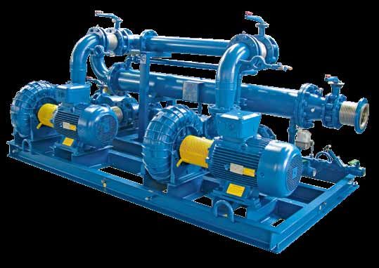
Sistema di Gestione della Qualità                                                   Quality Management System
Per avere un Sistema di Gestione di tutti i Processi Interni che                    In order to have a Management System of all Internal Processes
permetta di soddisfare i Clienti in modo efficiente ed efficace, nel                fit to satisfy Customers efficiently and effectively, in accordance
rispetto di:                                                                        with:
a. Leggi, Norme, Regolamenti e Direttive Europee                                    a. Laws, Norms, Rules and European Directives
b. Sicurezza                                                                        b. Safety
c. Ambiente                                                                         c. Environment
d. Etica e Rispetto                                                                 d. Ethics and respect
con attenzione a:                                                                   with focus on:
1. Miglioramento continuo                                                           1. Continuous improvement
2. Formazione del personale                                                         2. Staff training
3. Collaborazione con Fornitori e Clienti,                                          3. Cooperation with Customers and Suppliers,
Mapro S.p.A. ha implementato la Gestione della Qualità secondo la                   Mapro S.p.A. has implemented the Quality Management System
Norma ISO 9001:2008, ottenendo la Certificazione ICIM No.1835                       as per the requirements of ISO 9001:2008 Standard and obtained
con registrazione dell’lnternational Certification Network IQNet                    ICIM Certificate No. 1835 with International Certification
No. IT-18201.                                                                       Network IQNet registration No. IT-18201.
Tale Certificazione non rappresenta un fine, ma la prova del nostro                 This Certification is not an end, but the evidence of our
impegno al miglioramento continuo.                                                  Commitment to a Continuous process of Improvement.
In tutto il mondo, il marchio registrato MAPRO® è sinonimo di                       All over the world, the registered mark MAPRO ® is synonymous
qualità, efficienza e durabilità del prodotto.                                      with product quality, efficiency and durability.

  Organigramma                                                                                                                   Organization Chart
                                             SISTEMA INFORMATICO
                                             DATA PROCESSING DPT
                                                                                              SICUREZZA E AMBIENTE DI LAVORO
                                                                                                SAFETY & WORK ENVIRONMENT

                               AMMINISTRAZIONE
                              ADMINISTRATION DPT
                                                                        DIREZIONE                                    MARKETING
                                                                       MANAGEMENT                                   MARKETING DPT

                               VENDITE
                              SALES DPT
                                                                                         QUALITÀ DEL PRODOTTO E DEL SERVIZIO
                                                             SERVIZIO TECNICO               PRODUCT AND SERVICE QUALITY
                                                             ENGINEERING DPT

                                                                                                         PROGETTAZIONE & SVILUPPO
                               SERVIZIO POST-VENDITA                                                      DESIGN & DEVELOPMENT
                                                                                   ACQUISTI
                                AFTER-SALES SERVICE
                                                                                PURCHASING DPT

                                                      PRODUZIONE
                                                    PRODUCTION DPT

              COMPRESSORI E GRUPPI SU COMMESSA (Unità Produttiva "Fermi")            SOFFIANTI STANDARD E SU COMMESSA (Unità Produttiva "Vesuvio")
                COMPRESSORS AND PACKAGES ON ORDER ("Fermi" Factory)                    STANDARDIZED AND ON ORDER BLOWERS ("Vesuvio" Factory)
                                                                                                                                                          MA PRO

                                                                                                                                                              3
SOFFIANTI E COMPRESSORI PER BIOGAS E GAS NATURALE, in conformità alla Direttiva 94/9/CE (ATEX) BLOWERS AND COMPRESSORS FOR BIOGAS, LANDFILL AND ...
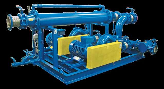
L’attività MAPRO® nasce da uno studio analitico delle esigenze           MAPRO ®’s activity originates from an analytical study of market
            di mercato e dalla conseguente progettazione delle macchine; si          requirements, develops through the design and improvement of
            sviluppa attraverso la realizzazione di prototipi, per arrivare infine   prototype machinery and finally leads to mass or custom-made
            alla produzione di serie o su commessa.                                  production.
            L’attenzione al mercato e la costante ricerca tecnologica, suppor-       The specific attention to the market requirements and the constant
            tata dal notevole e consolidato “know-how” aziendale, portano poi        technological research, supported by the significant and well-establi-
            alla continua evoluzione delle macchine prodotte.                        shed know-how, allows the constant development of the products.
            Un servizio tecnico-commerciale serio e competente è a disposizione      A qualified Technical Sales Department is at our customer’s
            per definire con il cliente la migliore scelta di macchina in funzione   disposal to set out the best machine choice for the operating
            delle condizioni operative previste per l’installazione.                 conditions foreseen for the plant.
            Il processo interno di fabbricazione, con le sue varie fasi di con-      The various checks required by the Quality Management System
            trollo previste dal Sistema di Gestione della Qualità, e con il severo   on the internal manufacturing process and the strict final test
            collaudo finale di ogni macchina, consente ai clienti di poter           of each machine, ensure that customers may always count upon
            contare sempre su prodotti affidabili e sicuri.                          reliable and safe products.
            Il servizio di assistenza post-vendita per ricambi, e per eventuali      The prompt spares availability and the after-sales service for
            riparazioni e manutenzioni con personale altamente qualificato,          maintenance and repairs carried out, on request, by skilled
            garantisce il regolare funzionamento nel tempo di qualunque              technicians, ensure the normal operation, year after year, of every
            macchina fornita.                                                        machine supplied.
    MAPRO

4
SOFFIANTI E COMPRESSORI PER BIOGAS E GAS NATURALE, in conformità alla Direttiva 94/9/CE (ATEX) BLOWERS AND COMPRESSORS FOR BIOGAS, LANDFILL AND ...
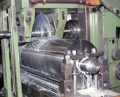
Per miscele di gas combustibili, quali gas biologico e gas            For the mixtures of combustible gases, such as biogas and
  naturale, MAPRO® ha voluto caratterizzare la sua specifica            natural gas, MAPRO ® has chosen to feature the specific
  tecnologia costruttiva per le soffianti e i compressori illu-         manufacturing technology used for the blowers and the
  strati nella presente brochure con il marchio                         compressors shown in this brochure with the trademark

  il quale ne sottolinea la progettazione espressamente dedi-           that highlights their design expressly worked out for the
  cata all’aspirazione ed alla compressione di tali gas.                extraction and compression of these gases.

Soffianti e Compressori in conformità                                 Blowers and Compressors in conformity
alla Direttiva 94/9/CE (ATEX)                                         with the 94/9/EC Directive (ATEX)
La Direttiva 94/9/CE (ATEX) richiede che in luoghi pericolosi,        The 94/9/EC Directive (ATEX) requires machines comprised in
classificati come Zona 1, per la probabile formazione di atmosfere    the Equipment-Group II, Category 2, for use in hazardous places,
potenzialmente esplosive costituite da una miscela di aria e gas      classified as Zone 1, where an explosive atmosphere, consisting of
infiammabili, vengano utilizzate apparecchiature rientranti nel       a mixture of ­air and flammable gases, is likely to occur.
Gruppo II, di Categoria 2.                                            In accordance with the Directive, MAPRO® has designed a complete
In accordo alla Direttiva, MAPRO® ha messo a punto una gamma          range of Blowers and Compressors, falling within the aforementioned
completa di Soffianti e Compressori, destinati alla compressione      Group, for the compression of combustible gases, such as biological
di gas combustibili, quali gas biologico o gas naturale, rientranti   or natural gas, and classified into Category 2 both for the surrounding
nel Gruppo suddetto, di Categoria 2 sia per l’ambiente circostante    area conditions and for the internals of the machines.
che per il loro interno.                                              The Annex VIll of the ATEX Directive defines the conformity
L’Allegato VIII della Direttiva ATEX definisce le procedure di        assessment procedures for the equipment. In accordance with
valutazione della conformità delle apparecchiature. In accordo        this Annex, MAPRO ® has communicated the Technical Dossier
a tale Allegato, MAPRO® ha depositato i Fascicoli Tecnici per le      for the various types of machine to the Italian Notified Body CESI
diverse macchine presso l’Organismo Notificato Italiano CESI          (Identification Number 0722).
(Numero ldentificativo 0722).                                         On the basis of the Technical Dossier contents, MAPRO ® follows
Sulla base di quanto espresso nei Fascicoli Tecnici, MAPRO®           the procedure relating to the internal control of production of
esegue quindi il controllo di fabbricazione interno delle macchine    the machines and draws up the relevant written Declaration of
ed emette il Certificato di Conformità delle stesse alla Direttiva.   Conformity to the Directive.
                                                                                                                                                MA PRO

                                                                                                                                                    5
SOFFIANTI E COMPRESSORI PER BIOGAS E GAS NATURALE, in conformità alla Direttiva 94/9/CE (ATEX) BLOWERS AND COMPRESSORS FOR BIOGAS, LANDFILL AND ...
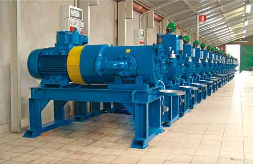
SOFFIANTI A CANALE LATERALE per BIOGAS e GAS NATURALE
          SIDE CHANNEL BLOWERS for BIOGAS and NATURAL GAS
            Principio di funzionamento                                             Operating principle
            Il principio di funzionamento delle macchine a canale late-            The side channel blower increases the pressure of the
            rale consiste nelI’incrementare la pressione del gas aspirato          aspirated gas by the creation, in the peripheral toroidal
            tramite la creazione, nel canale toroidale periferico,                                 channel, of a series of vortexes caused
            di una serie di vortici determinati dalla spinta                                          by the centrifugaI thrust of the impeller.
            centrifuga del rotore alettato.                                                            While the impeller is rotating, the
            Con la girante in rotazione, le palette spingono                                             vanes force the gas forward and,
            il gas in avanti e, per effetto della forza centri-                                           because of the centrifugaI thrust,
            fuga, verso I’esterno.                                                                         outwards, producing a helical
            Ne risulta un moto elicoidale,                                                                 motion.
            durante il quale il gas subisce                                                               During this motion, the gas is
            una serie di ricompressioni dovute                                                           recompressed repeatedly with a
            alla forza centrifuga, con conseguente                                                       consequent linear pressure increase
            incremento lineare di pressione lungo il                                                     along the length of the channel.
            canale.

            Generalità e soluzioni costruttive                                     Generalities and construction
            in conformità alla Direttiva                                           features in conformity with
            94/9/CE (ATEX)                                                         the 94/9/EC Directive (ATEX)
            Le soffianti a canale laterale MAPRO® destinate alla compres-          The MAPRO® side channel blowers to be used for extraction or com-
            sione di gas combustibili, quali gas biologico o gas naturale,         pression of combustible gases, such as biological or natural gas,
            sono apparecchi rientranti nel Gruppo II così come definito dalla      have been designed in order to fall within the Equipment-Group II
            Direttiva 94/9/CE (ATEX), di Categoria 2 sia per l’ambiente cir-       as defined by the 94/9/EC Directive (ATEX), Category 2 both for the
            costante che per il loro interno, e sono quindi macchine a tenuta      surrounding area conditions and for the internals of the machines.
            ermetica con le seguenti peculiarità costruttive:                      They are therefore gas-tight blowers, with the following con-
            • carcasse e giranti interamente realizzate in lega di alluminio      struction features:
               antiscintilla;                                                      • casing and impellers made completely of spark proof
            • trattamento di impregnazione con Loctite delle parti destinate         aluminium alloy;
               a contenere il gas;                                                 • casing impregnated with Loctite;
            • sigillatura tra i fondi costituenti il corpo macchina;              • casing halves sealed;
            • tenuta sull’albero realizzata con speciali anelli a doppio labbro   • shaft sealing by special double-lip seals which do not
               che non richiedono lubrificazione;                                     require lubrication;
            • motori elettrici, a due poli, in esecuzione antideflagrante, modo   • two-pole, type of protection “d”, flameproof electric motors,
               di protezione “d”, con marcatura specifica Ex II 2 G, marcatura        with specific marking Ex II 2 G, additional marking Ex-d IIB T3.
               complementare Ex-d IIB T3.                                          The simplest solution for the manufacturing of the machines
            La soluzione costruttiva più semplice è nella cosiddetta               is the so-called “CLOSE COUPLED” version – i.e., a flange
            “esecuzione monoblocco”. La flangia anteriore del motore elettrico     mounted electric motor is bolted to the blower casing; the
            è direttamente fissata al corpo macchina e la girante, bilanciata
                                                                                   impeller, which is dynamically balanced, is fitted directly
            dinamicamente, è calettata sul capo d’albero del motore stesso.
                                                                                   onto the motor shaft extension.
    MAPRO

6
SOFFIANTI E COMPRESSORI PER BIOGAS E GAS NATURALE, in conformità alla Direttiva 94/9/CE (ATEX) BLOWERS AND COMPRESSORS FOR BIOGAS, LANDFILL AND ...
Furthermore, we can offer machines with their own shaft and
                                                                     bearings and coupled to the electric motors via flexible shaft
                                                                     couplings or belt drives. In these cases, the safety drive guards
                                                                     are made from spark-free material.
                                                                     If the area surrounding the equipment is classified as Zone 2,
                                                                     where, for the Group II, Category 3 equipments are accepted,
                                                                     the machine could be equipped with the type of protection “n”
                                                                     non-sparking motor, with specific marking Ex II 3 G, additional
                                                                     marking Ex-nA II T3.
                                                                     In some particular cases, all the internal aluminium parts
                                                                     wetted by gas can be treated with anodic oxidation; the machine
Possono inoltre essere fornite macchine con proprio albero e         can be supplied with its own shaft and external bearing hous-
cuscinetti, accoppiate al motore elettrico tramite giunto elastico   ings, so that the bearings are completely isolated from the gas
o a mezzo cinghie e pulegge, con carter di protezione delle tra-     handled; and it is also possible to fit lip seals in pairs, with a
smissioni in materiale antiscintilla.                                barrier fluid in between.
Nel caso in cui l’ambiente circostante venga classificato come
Zona 2, per la quale sono quindi ammesse, per il Gruppo II,
apparecchiature di Categoria 3, il motore elettrico della macchi-
na potrà essere in esecuzione antiscintilla, modo di protezione
“n”, con marcatura specifica Ex II 3 G, marcatura complemen-
tare Ex-nA II T3.
In alcuni casi particolari possono essere eseguiti trattamenti
                         di ossidazione anodica su tutte le
                         parti in alluminio in contatto col
                          gas, possono essere fornite macchi-
                          ne con proprio albero e cuscinetti
                          montati su mozzi esterni completa-
                           mente isolati rispetto al gas di pro-
                               cesso, e ancora possono essere        Advantages
                                            montate coppie con-      The main advantages of using side channel machines are:
                                              trapposte di anelli    • easy installation;
                                                di tenuta a lab-     • low noise level;
                                                  bro tra i quali    • no vibration;
                                                   viene immesso     • pulsation free gas flow;
                                                   un fluido di      • minimal maintenance.
                                                 sbarramento.        Moreover no internal lubrication is necessary, and therefore the
                                                                     gas moving through the machine remains uncontaminated and
                                                                     completely oil-free.
                           Vantaggi
                      I maggiori vantaggi nell’utilizzo delle
soffianti a canale laterale sono:
                                                                     The most common fields of application
                                                                     • Landfill biogas recovery to feed torch, burner or gas engine;
• massima semplicità di installazione;
                                                                     • tank, plant or contaminated soil gas recovery to feed torch or burner;
• rumorosità molto contenuta;
                                                                                                           • extraction of biogas from
• assenza di vibrazioni;
                                                                                                              gasometer, natural gas from
• assenza di pulsazioni nel flusso di gas trattato;
                                                                                                                pipeline or gasometer, and
• minima manutenzione.
                                                                                                                  burner or gas engine
Le macchine inoltre non richiedono lubrifi-
                                                                                                                   feeding.
cazione e quindi il gas convogliato non
viene assolutamente inquinato.

Applicazioni più
comuni
• Aspirazione di biogas da
   discariche controllate e invio
   a torcia, a bruciatore o motore
   a gas;
• aspirazione di gas da serbatoi,
                                                                                                                                                 MA PRO

   impianti o terreni da bonificare e invio a
   torcia o a bruciatore;
• aspirazione di biogas da gasometro, di gas naturale da rete
   o da gasometro e invio a bruciatore o motore a gas.
                                                                                                                                                     7
SOFFIANTI E COMPRESSORI PER BIOGAS E GAS NATURALE, in conformità alla Direttiva 94/9/CE (ATEX) BLOWERS AND COMPRESSORS FOR BIOGAS, LANDFILL AND ...
Macchine con ricircolo del gas (by-pass)                                 Machines with gas recirculation (by-pass)
            Per tutti i casi in cui il gas aspirato debba essere inviato a un bru-   When the gas has to feed a burner or when a variable gas flow
            ciatore, o comunque a un utilizzo che richieda una portata variabi-      is required, a “compact by-pass”, directly bolted to the machine
            le nel tempo, un sistema semplice ed efficace per soddisfare tale        and connecting outlet and inlet ports, is a simple and effective
            variabilità è costituito da un “by-pass compatto”, direttamente          solution. A suitable overpressure relief valve is fitted inside the
            montato tra la mandata e l’aspirazione, all’interno del quale viene      “compact by-pass”.
            installata un’opportuna valvola di sovrappressione.
            Allorchè la portata richiesta all’utilizzo diminuisce, la pressione
            alla mandata della macchina tende ad aumentare. Al raggiungi-
            mento della pressione di taratura, la valvola di sovrappressione
            inizia ad aprirsi e a ricircolare la portata di gas in esubero. Per
            bassi differenziali di pressione, il “by-pass compatto” consente
            abitualmente il ricircolo dell’intera portata e la macchina può
            quindi continuare a funzionare anche se l’utilizzo non richiede gas.

                                                                                     When the gas demand decreases, the outlet pressure increases,
                                                                                     and, when the set pressure is reached, the overpressure relief
                                                                                     valve starts to open and by-passes excess gas back to the blower
                                                                                     suction.
                                                                                     In case of low differential pressure, usually the “compact by-
                                                                                     pass” is capable of handling the full capacity of the blower and
                                                                                     thus the machine can continue to run even if the downstream gas
                                                                                     demand is reduced to zero.
            Per differenziali di pressione più elevati, che non consentono           For higher differential pressures, where the use of a “compact
            l’utilizzo di un “by-pass compatto” per l’eccessivo incremento di        by-pass” is not allowed because of the high temperature increase
            temperatura durante il ricircolo completo del gas, la soffiante può      when the full capacity of the blower is by-passed back to the
            essere fornita con valvola di sovrappressione installata in deriva-      suction, the machine can be supplied with the overpressure relief
            zione alla mandata.                                                      valve fitted on an offtake at the outlet side.
            In tal caso lo scarico flangiato della valvola potrà essere collegato    In that case the flanged valve discharge could be piped-back to
            alla linea di aspirazione attraverso una tubazione di “by-pass” di       the blower suction through a by-pass pipe long enough to allow
            lunghezza tale da consentire il sufficiente raffreddamento del gas       for sufficient gas cooling.
            durante il ricircolo.                                                    On request, we can also offer machines equipped with a suitable
                                                                                     gas cooler at the blower outlet, with overpressure relief valve fitted
                                                                                     in an offtake at the cooler outlet, and with the complete “by-pass
                                                                                     pipe” back to the blower suction side.
                                                                                     We can also offer automatic flow rate adjustment by means of
                                                                                     pneumatic or electrically operated flow control valve, fitted in
                                                                                     the by-pass line and controlled via the client process parameter
                                                                                     “discharge gas pressure”.

            Possiamo anche proporre, su richiesta, soffianti provviste, in man-
            data, di adeguato raffreddatore del gas di tipo a fascio tubiero, di
            valvola di sovrappressione in derivazione e della relativa tubazio-
    MAPRO

            ne di ricircolo all’aspirazione.
            Possiamo proporre inoltre, su richiesta, sistemi di regolazione
            automatica della portata mediante valvola a comando pneumati-
            co o motorizzata installata lungo il by-pass ed azionata attraverso
8           il controllo del parametro “pressione di mandata”.
SOFFIANTI E COMPRESSORI PER BIOGAS E GAS NATURALE, in conformità alla Direttiva 94/9/CE (ATEX) BLOWERS AND COMPRESSORS FOR BIOGAS, LANDFILL AND ...
Macchine azionate tramite inverter                                          Machines controlled via frequency inverter
Nel caso in cui la portata di gas richiesta all’utilizzo sia variabile      If the gas demand varies in time (such as for burner or
nel tempo (alimentazione a bruciatore o motore a gas), possono              engine feeding), we can supply blowers equipped with a motor
essere fornite soffianti con motore destinato ad essere azionato            intended for control via frequency inverter. The rpm range of
tramite inverter. Il campo di variazione della velocità di rotazione        the blower (and therefore the output frequency range of the
della macchina (e quindi della frequenza di alimentazione del               frequency inverter) can be adjusted according to the foreseen
motore elettrico) sarà definito in funzione delle condizioni di lavoro      operating conditions, and in particular to the expected differ-
previste, in particolare del differenziale di pressione tra aspira-         ential pressure between blower discharge and suction.
zione e mandata della macchina. La regolazione della velocità di            The speed of rotation of the motor shall be controlled via the
rotazione potrà essere fatta in funzione del controllo del parametro        “discharge gas pressure” process parameter.
“pressione di mandata”.
                                                                            Accessories
                                                                            A complete range of accessories is available, including the following:
                                                                            • gas-tight filters;
                                                                            • stainless steel flanged flexible connection bellows;
                                                                            • non return valves;
                                                                            • pressure gauges and thermometers;
                                                                            • explosion-proof pressure switches and temperature switches;
                                                                            • intrinsically-safe pressure and temperature transducers;
                                                                            • manual and automatic cut-off valves;
                                                                            • acoustic enclosures.

Accessori
È disponibile una linea completa di accessori che comprende, tra l’altro:
• filtri a tenuta stagna;
• compensatori flangiati di collegamento con soffietto inox;
• valvole di ritegno;
• manometri e termometri;
• pressostati e termostati in esecuzione antideflagrante;
• trasduttori di pressione e temperatura a sicurezza intrinseca;
• valvole di esclusione manuali ed automatiche;
• cabine insonorizzanti.

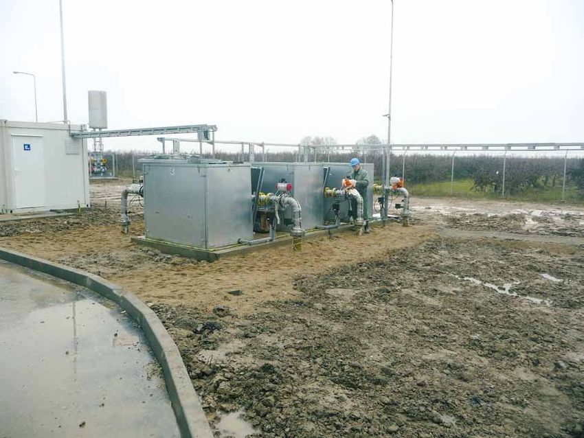
                                              Alcune installazioni / Some installation

                                                                                                                                                     MA PRO

                                                                                                                                                         9
SOFFIANTI E COMPRESSORI PER BIOGAS E GAS NATURALE, in conformità alla Direttiva 94/9/CE (ATEX) BLOWERS AND COMPRESSORS FOR BIOGAS, LANDFILL AND ...
10
                      MAPRO
Campo di utilizzo soffianti a canale laterale per biogas                                                                                                                                                                                                                               Side channel blowers for biogas - Range of duty

                            600                                                                                                                                                                                                                                                                                                                                                             600

                            550                                                                                                                                                                                                                                                                                                                                                             550
                                                                                                                                                                                                                                                                                                                                               Legenda             Key

     [hPa = mbar]
     [hPa = mbar]
                                                                                                                                                                                                                                                                                                                            60/1               Tipo macchina       Machine type
                            500      CL 12/21 CL 14/21 CL 17/21                           CL 20/21               CL 23/21              CL 30/21       CL 36/21 CL 42/21                                            CL 49/21                                                                                                 11                 Potenza motore (kW) Motor power (kW)         500
                                               3      3                 4                      5,5                      5,5               7,5                 9,2             11                                      15

                            450                                                                                                                                                                                                                                                                                                                                                             450
                                                                                                         4                                                        7,5                       9,2                                      11

                            400                                                                                                                   CL 46/1                                                        CL 84/1                                                CL 98/1                                                                                                             400

     Pressione di mandata
     Outlet pressure
                                                          2,2                                                                                               9,2                                                    18,5                          9,2                        18,5
                                                                                 2,2                                                       CL 40/1                                      CL 60/1 CL 72/1
                                                                                                                                                7,5                                          11             15                   15
                            350                                                                                    CL 34/1                                                                                                                                                                                                                                                                  350
                                                                                                                        5,5                                             5,5
                                                                                        CL 28/1 3                                                                                                                          7,5   11
                                                                                                     4
                            300                                                                                                                         4                                                    7,5                 9,2                                                                                                                                                        300
                                                                                                                                   3                                              5,5               5,5                                                                                                    15
                                                                                                     CL 22/01                                                                                                                                                     7,5
                                                                                                             4
                            250                                    CL 18/01                                                                                                                                                                                                                                                                                                                 250
                                                                            3            1,5                                       3                                                                                                                             9,2                             11
                                                          CL 15/01                                           1,5                                                                        4
                                                           1,5                                                                                                                                          4                                                  7,5
                            200        CL 10/01                                                                                                                               3                                                                                                          7,5                                                                                                200
                                             1,1                                                         2,2                       2,2                                                                                                     5,5                                                                  9,2
                                                                                                                                                                                                                                 4                         5,5                     5,5
                                                                                                                                                       3                                                                    4                                                                                                      11
                            150      CL 7/01                                                              1,1               1,1                                          2,2                                          3                                                                  5,5                                                                                                150
                                      0,75
                                     CL 4/01                                                                      1,1                                                                                                      3                                            4                                 5,5                    7,5
                                                   0,37
                                                                                                                                                                                              2,2                                                      3                                                                                 9,2
                            100    CL 3.6/01                                                                                                                                                                                                                                                                                                                                                100
                                         0,25                    0,55                  0,75                                                           1,5

                                                                                                                                                                                                  1,5                                2,2                                           3                  4                                         7,5
                            50                                                                                                                                                                                                                                                                                                                                                              50

                              0                      20                         40              60                 80             100                             150                                   200                    250               300               350             400         450    500             600          700         800       900 1000 1100 1200 1300
                                                                                                                                                                                                                                                                                                                                                                         Portata [m3/h]
                                                                                                                                                                                                                                                                                                                                                                         Flow rate [m3/h]

                                  Le curve "portata-pressione" e le “potenze motore” mostrate, unicamente a titolo indicativo,                                                                                                                                         The performance curves “flow rate - outlet pressure” and the “motor powers” shown in the
                                  all’interno del campo di utilizzo, si intendono per macchine a velocità fissa (50Hz – 2900giri/min),                                                                                                                                 literature, are given, as an indication only, at fixed rpm (50Hz – 2900rpm) and for a biogas
                                  e per un gas biologico di peso specifico 1,14kg/Nm3.                                                                                                                                                                                 with specific weight 1.14kg/Nm3.
                                  La pressione d’aspirazione è considerata a 10mbar g e la temperatura d’aspirazione a 35°C.                                                                                                                                           The suction pressure is assumed at 10 mbarg and the inlet temperature at 35°C.

                                  La parte di curva in colore rosso è riferita al campo di pressione in cui è possibile l’utilizzo della                                                                                                                               The part of the curves in red colour refers to the pressure range in which the blowers fitted
                                  macchina con “by-pass compatto”.                                                                                                                                                                                                     with a “compact by-pass” can be used.
Dimensioni                                                                                   Dimensions
Di seguito vengono riportate, fino a pagina 13, a titolo indicativo, le                      Below, and up to page 13, you can find, as an indication, the
dimensioni delle soffianti monostadio, per biogas o gas naturale, in                         dimensions of the single-stage side channel blowers, for biogas or
esecuzione “monoblocco”.                                                                     natural gas, in the so-called “CLOSE COUPLED” version.
Le soffianti si intendono equipaggiate con motore elettrico in ese-                          The blowers shown are equipped with the type of protection “d”
cuzione antideflagrante, modo di protezione “d”, con marcatura                               flameproof electric motor, with specific marking Ex II 2 G, addi-
specifica Ex II 2 G, marcatura complementare Ex-d IIB T3.                                    tional marking Ex-d IIB T3.
L’altezza ed il peso indicati si riferiscono a macchine equipaggiate                         The height and weight given are for the blowers equipped with
con motore elettrico di potenza la più alta prevista per lo specifico                        the motor of the highest power rating amongst those provided for
modello di soffiante.                                                                        the specific blower model.
Per le dimensioni e le potenze installate di qualunque altra solu-                           For the dimensions and the motor power of any other construction
zione costruttiva, contattare il Servizio Vendite MAPRO®.                                    feature, please ask the MAPRO ® Sales Department.

       Soffianti a canale laterale con filtro in aspirazione e curve flangiate in aspirazione e mandata
                 Side channel blowers with inlet filter and inlet and discharge flanged elbows
                                              G
                                                             N
                                                                      O

                                                                                                          C
  I

                                                                                             I

                                                                                                              H

                                                             L                                                           M                                E
                                                                                             8
  8

                                                A                                                                                                  B

   N.B.: per le CL 3.6/01 VG e CL 4/01 VG la posizione dei piedi di supporto è ruotata di 60° rispetto a quanto mostrato in figura
   N.B.: the feet position for CL 3.6/01 VG and CL 4/01 VG is turned by 60° compared to the figure
                                                                                                                               0°
                                                                                                                             12

                                                                                                                   øF

                                                                                                                                              øD

        Tipo     Potenze motori a 50Hz                                                                                                  ASPIRAZIONE      MANDATA         Peso
     macchina
                  50Hz motor powers             A      B      C    øD      E     øF     G      H      I       L     M    N        O        INLET          OUTLET        Weight
      Machine
        type              [kW]                                                                                                           EN 1092-1       EN 1092-1        [kg]
    CL 3.6/01 VG          0,25                 553    330   406    290    123    10    553    32    143       55    70   320      160    PN16 DN25      PN16 DN25          30
    CL 4/01 VG            0,37                 553    330   406    290    123    10    553    32    143       55    70   320      160    PN16 DN25      PN16 DN25          30
    CL 7/01 VG        0,55 - 0,75              535    380   406    340    125    10    520    32    200       55    70   290      145    PN16 DN40      PN16 DN40          37
    CL 10/01 VG        0,75 - 1,1              555    420   411    370    145    10    530    32    210       55    70   300      150    PN16 DN50      PN16 DN50          41
                                                                                                                                                                                     MA PRO

    CL 15/01 VG         1,1 - 1,5              580    460   466    410    170    10    545    32    225       55    70   310      155    PN16 DN50      PN16 DN50          52
    CL 18/01 VG       1,5 - 2,2 - 3            695    535   536    430    202    10    665    32    280       55    70   368      184   PN16 DN65(*)   PN16 DN65(*)        72
    CL 22/01 VG        2,2 - 3 - 4             725    565   561    465    216    10    685    32    295       55    70   390      195   PN16 DN65(*)   PN16 DN65(*)        94
   Dimensioni (mm) - Dimensions (mm)                                                                                                      (*) Flangia a 4 fori – (*) 4-hole flange
                                                                                                                                                                                         11
G                                                          B
                                                                                                                                                N

                                                                                                                                                                                                                 C
                                                                                    I

                                                                                                                                                                    I
                                                                                                                                                        O                                              E

                                                                                    8

                                                                                                                                                                    8
                                                                                                                                                D                                             D
                                                                                                                                                P                                             P
                                                                                                                                       A

                                                                                                                                                                                                               D
         Soffianti a canale laterale con filtro in aspirazione
         e curve flangiate in aspirazione e mandata                                                                                                                                               øF
         Side channel blowers with inlet filter and inlet and discharge flanged elbows

          Tipo macchina Potenze motori a 50Hz                                                                                                                       ASPIRAZIONE             MANDATA   Peso
                          50Hz motor powers                 A         B         C         D         E        øF           G            I       N       O     P         INLET                 OUTLET  Weight
           Machine type           [kW]                                                                                                                               EN 1092-1            EN 1092-1   [kg]
            CL 28/1 VG        1,5 - 2,2 - 3                725       530       590      460       174        11       655          290         360     180   500    PN16 DN65(*)        PN16 DN65(*)   88
            CL 34/1 VG      2,2 - 3 - 4 - 5,5              735       535       665      460       180        11       675          320         380     190   500    PN16 DN65(*)        PN16 DN65(*) 109
            CL 40/1 VG   2,2 - 3 - 4 - 5,5 - 7,5           805       580       665      530       190        11       725          325         410     205   570     PN16 DN80           PN16 DN80    126
            CL 46/1 VG      3 - 4 - 5,5 - 7,5              815       590       715      530       200        11       745          360         430     215   570     PN16 DN80           PN16 DN80    136
            CL 60/1 VG        4 - 5,5 - 7,5                815       590       695      530       200        11       745          380         430     215   570     PN16 DN80           PN16 DN80    138
            CL 72/1 VG       5,5 - 7,5 - 9,2               885       655       730      570       220        11       810          340         456     228   610     PN16 DN100          PN16 DN100   142
            CL 84/1 VG       5,5 - 7,5 - 9,2               910       715       745      620       255        11       810          365         456     228   660     PN16 DN100          PN16 DN100   151
            CL 98/1 VG       5,5 - 7,5 - 9,2               930       745       735      660       265        11       810          355         456     228   700     PN16 DN100          PN16 DN100   153
         Dimensioni (mm) - Dimensions (mm)                                                                                                                                 (*) Flangia a 4 fori – (*) 4-hole flange

                                                                                                                                               O
                                                                                                                                                                    C
                                                                           I

                                                                                                                                                             I

                                                                                                                                                                     H

                                                                                                                                       L                                      M                        E
                                                                           8

                                                                                                                                                             8

                                                                                                                      A                                                                           B
                                                                                                                                       N
                                                                                                                      G
                                                                                                                                                                                       0°
                                                                                                                                                                                   12
         N.B.: per le CL 3.6/01 VG e CL 4/01 VG la posizione dei piedi di supporto è ruotata di 60° rispetto a quanto mostrato in figura
         N.B.: the feet position for CL 3.6/01 VG and CL 4/01 VG is turned by 60° compared to the figure
                                                                                                                                                                                                                øD

                                                                                                                                                                                                       øF
         Soffianti a canale laterale con filtro in aspirazione e by-pass compatto
         Side channel blowers with inlet filter and compact by-pass
                       Potenze motori a 50Hz                                                                                                                              ASPIRAZIONE        MANDATA         Peso
         Tipo macchina
                        50Hz motor powers              A         B         C        øD        E         øF        G           H            I       L     M     N     O       INLET            OUTLET        Weight
          Machine type
                                [kW]                                                                                                                                       EN 1092-1         EN 1092-1       [kg]
          CL 3.6/01 VG          0,25                  503       323       406       290       115       10    493             32       136      55      70    260   130    PN16 DN25         PN16 DN25        30
          CL 4/01 VG            0,37                  503       323       406       290       115       10    493             32       136      55      70    260   130    PN16 DN25         PN16 DN25        30
          CL 7/01 VG        0,55 - 0,75               570       390       206       340       125       10    570             32       160      55      70    340   170    PN16 DN40         PN16 DN40        39
 MAPRO

          CL 10/01 VG        0,75 - 1,1               575       425       411       370       145       10    570             32       165      55      70    340   170    PN16 DN50         PN16 DN50        43
          CL 15/01 VG         1,1 - 1,5               595       470       446       410       170       10    575             32       180      55      70    340   170    PN16 DN50         PN16 DN50        50
          CL 18/01 VG         1,5 - 2,2               710       535       471       430       200       10    695             32       215      55      70    400   200   PN16 DN65(*)      PN16 DN65(*)      65
          CL 22/01 VG          2,2 - 3                730       565       541       465       215       10    695             32       230      55      70    400   200   PN16 DN65(*)      PN16 DN65(*)      81
         Dimensioni (mm) - Dimensions (mm)                                                                                                                                 (*) Flangia a 4 fori – (*) 4-hole flange
12
G
                                                                                                                              N
                                                                                                                                     O

                                                                                                                                                            C
                                                                                   I

                                                                                                                                                     I
                                                                                                                                                                                              E

                                                                                                                                                     8

                                                                                                                                                            8
                                                                                   8
                                                                                                                              D                                                       D
                                                                                                                              P                                                       P
                                                                                                                    A                                                                 B

   Soffianti a canale laterale con filtro in aspirazione e by-pass compatto
   Side channel blowers with inlet filter and compact by-pass

     Tipo macchina Potenze motori a 50Hz                                                                                                                 ASPIRAZIONE          MANDATA     Peso
                    50Hz motor powers     A    B   C                                   D         E   øF    G        I        N       O       P              INLET              OUTLET    Weight
      Machine type          [kW]                                                                                                                          EN 1092-1           EN 1092-1   [kg]
       CL 28/1 VG       1,5 - 2,2 - 3    745 530 590                                 460     175     11   695     245        400    200      500         PN16 DN65(*)       PN16 DN65(*)   77
       CL 34/1 VG        2,2 - 3 - 4     745 535 630                                 460     180     11   695     270        400    200      500         PN16 DN65(*)       PN16 DN65(*)   99
       CL 40/1 VG        3 - 4 - 5,5     805 585 630                                 530     190     11   715     260        400    200      570          PN16 DN80          PN16 DN80    101
       CL 46/1 VG        3 - 4 - 5,5     805 595 675                                 530     200     11   715     295        400    200      570          PN16 DN80          PN16 DN80    119
       CL 60/1 VG       4 - 5,5 - 7,5    800 595 695                                 530     200     11   715     315        400    200      570          PN16 DN80          PN16 DN80    138
       CL 72/1 VG       4 - 5,5 - 7,5    1020 695 685                                570     220     11   980     285        500    265      610          PN16 DN100         PN16 DN100   155
       CL 84/1 VG      5,5 - 7,5 - 9,2   1045 755 745                                620     255     11   980     310        500    265      660          PN16 DN100         PN16 DN100   173
       CL 98/1 VG         7,5 - 9,2      1065 785 740                                660     265     11   980     305        500    265      700          PN16 DN100         PN16 DN100   175
   Dimensioni (mm) - Dimensions (mm)                                                                                                                            (*) Flangia a 4 fori – (*) 4-hole flange

La marcatura ATEX delle soffianti a canale laterale MAPRO® per biogas o gas naturale
The ATEX marking of MAPRO ® side channel blowers for biogas or natural gas
                                   Numero di identificazione del Fascicolo Tecnico MAPRO
                                   depositato presso l'Organismo Notificato CESI (0722)
                                   Identification number of the MAPRO Technical File
                                   communicated to the Notified Body CESI (0722)
                                                                                                                                                 20834

                           20834
                                                                                                                                             {
                                                                                                                                             {

                                                                                                                                                                                    {
                                                                                                                                                                                    {

                                                                                                      Gruppo di apparecchi                                                                  Classe di temperatura
                                                                                                      Equipment group                                                                       Temperature class
                                         {
                                         {

                                                                                                                Categoria                                                                   Gruppo di gas
                                                                                                                Category                                                                    Gas group
                                                                                                                                                                                                                    MA PRO

                                                Gruppo di gas            Classe di temperatura             Tipo di protezione dall'innesco                                      Tipo di protezione dall'innesco
                                                Gas group                Temperature class                 Type of ignition protection                                          Type of ignition protection
                                                                                                                                   Gruppo di gas                        Categoria
Gruppo di apparecchi                   Tipo di protezione dall'innesco
                                                                                                                                   Gas group                            Category
Equipment group                        Type of ignition protection
                       Categoria                                                                                                   Classe di temperatura           Gruppo di apparecchi
                       Category                                                                                                    Temperature class               Equipment group                                      13
SOFFIANTE TURBOTRON® per BIOGAS e GAS NATURALE
           TURBOTRON ® BLOWER for BIOGAS and NATURAL GAS
         Principio di funzionamento e vantaggi                                 Operating principle
         Il Turbotron® è una macchina con canale toroidale periferico,         The Turbotron® is a machine with a peripheral toroidal channel,
         come le soffianti a canale laterale, ma con una girante e              similar to side channel blowers, but featuring a revolutionary
         un canale di concezione altamente innovativa, frutto di                           impeller and channel design, developed through long
         un lungo lavoro di ricerca e sperimentazione.                                      research and tests.
         Il principio di funzionamento e i vantaggi sono gli stes-                          The operating principle, and advantages are the same
         si delle soffianti a canale laterale. Tuttavia, le palette                        as side channel blowers, and yet, the wing contour of
         a profilo alare della girante e il canale con nocciolo                             the impeller vanes and the peripheral channel with the
         centrale consentono di raggiungere prestazioni                                       central core allow the achievement of performances
         prossime a quelle delle soffianti volumetriche a                                          similar to positive displacement machines.
         lobi rotanti.
                                                                                                    Generalities and construc-
         Generalità e soluzioni                                                                     tion features in conformity
         costruttive in conformità                                                                  with the 94/9/EC
         alla Direttiva 94/9/CE                                                                     Directive (ATEX)
         (ATEX)                                                                                      Construction features are the same as side
         Le peculiarità costruttive sono le stesse delle soffianti a             channel blowers. But, differently from the side channel machines,
         canale laterale. I Turbotron® destinati alla compressione di            the Turbotron® blowers designed to extract or compress com-
         gas combustibili, quali gas biologico o gas naturale, sono tuttavia   bustible gases, such as biological or natural gas, are always
         sempre costruiti nella versione con proprio albero e cuscinetti.      manufactured with their own shaft and bearings. Sometimes they
         L’accoppiamento al motore elettrico può essere realizzato tramite     are coupled to the electric motors via a flexible shaft coupling.
         giunto elastico o, assai più spesso, a mezzo cinghie e pulegge.       In general they are coupled to the electric motors via belt drives.
         Infatti il Turbotron®, nella versione per gas combustibili, è pro-    This is because the Turbotron® for combustible gases is a machine
         gettato per un’ampia gamma di velocità di rotazione (da 2000 a        designed for a wide range of permissible operating speeds of
         5000 giri/min), e questo consente di coprire, con una sola taglia     rotation (from 2000 to 5000 rpm), and therefore, a very large
         di macchina, un larghissimo campo di funzionamento.                   operating range can be achieved using a single machine size.

         Applicazioni - Macchine con ricircolo                                 Fields of application - Machines with
         del gas - Azionamento tramite inverter                                gas recirculation - Control via frequency
         - Accessori                                                           inverter - Accessories
         Vale quanto detto per le soffianti a canale laterale con l’unica      Everything said for the side channel machines also applies to the
         annotazione che, per il Turbotron®, non è prevista la soluzione       Turbotron® blower with the exception of the “compact by-pass”
         costruttiva del “by-pass compatto” direttamente montato tra la        solution which is not available for this type of machine.
         mandata e l’aspirazione. La valvola di sovrappressione, quando        The overpressure relief valve, when provided, is always fitted on an
         prevista, è sempre installata su derivazione alla mandata.            offtake at the discharge side.
 MAPRO

14
Campo di utilizzo Turbotron® per biogas                                                                                                                 Turbotron® for biogas – Range of duty
                                           bar g   hPa g
                                            0,9    900
  Pressione di mandata - Outlet pressure

                                                                                                                                                                                                                 Legenda               Key
                                           0,8     800                                                                                                                                                           Potenza motore (kW) Motor power (kW)
                                                                                                                                              55                       75                    18,5

                                           0,7     700                                                                   45
                                                                                                                                                                               55

                                                                                                                                                                                    45
                                                                                                                                                           40

                                                                                                                                                                                      00
                                           0,6     600

                                                                                                                                                             00
                                                                                                                                                          45

                                                                                                                                                                                         gir
                                                                                                                                                                gir
                                                                                                    30                              37

                                                                                                                                          35

                                                                                                                                                                                            i/1
                                                                                                                                                                   i/1
                                                                                                                                            00

                                                                                                                                                                      ’

                                                                                                                                                                                               ’
                                           0,5     500

                                                                                                                                                                       -r

                                                                                                                                                                                            -r
                                                                                                                                               gir

                                                                                                                                                                         pm

                                                                                                                                                                                              pm
                                                                                                                                                  i/1
                                                                                        22                                                                                    37           45
                                                                                                                         29

                                                                                                                                                     ’
                                                                                                                                                     -r
                                                                                                                           00
                                           0,4     400

                                                                                                                                                       pm
                                                                                                                                                   30
                                                                                                                              gi
                                                                            15                              25           22 ri/1
                                                                                                  18,5
                                                                                                              00                 ’   -r
                                           0,3     300                                                           gir                   pm                                             30                    37
                                                                                                                    i/1
                                                                                                                   15  ’   - rp    18,5                           22
                                                                                                  200                          m
                                           0,2     200                                       11       0g                                                                                                             30
                                                                                                        iri/
                                                                                                   9,2      1’ -                                15                          18,5                    22
                                                                                                                   rpm
                                                                                                                                     11
                                           0,1     100                                                       7,5

                                              0       0            100 200 300 400 500 600 700 800 900 1000 1100 1200 1300 1400 1500 1600 1700 1800 1900 2000
                                                                                                                                                                                                                   Portata [m3/h] - Flow rate [m3/h]

                       Le curve “portata-pressione” e le “potenze motore” mostrate, unicamente a                                                        The performance curves “flow rate - outlet pressure” and the “motor
                       titolo indicativo, all’interno del campo di utilizzo, si intendono per Turbotron®                                                powers” shown in the literature, are given, as an indication only, at fixed
                       a velocità fissa e per un gas biologico di peso specifico 1,14kg/Nm3.                                                            rpm and for a biogas with specific weight 1.14kg/Nm3.
                       La pressione d’aspirazione è considerata a 10mbar g e la temperatura                                                             The suction pressure is assumed at 10 mbarg and the inlet tempera-
                       d’aspirazione a 35°C.                                                                                                            ture at 35°C.

La marcatura ATEX della soffiante Turbotron® per biogas o gas naturale
The ATEX marking of the Turbotron® blower for biogas or natural gas
                                                                    Numero di identificazione del Fascicolo Tecnico MAPRO
                                                                    depositato presso l'Organismo Notificato CESI (0722)
                                                                    Identification number of the MAPRO Technical File                                                                               20834
                                                                    communicated to the Notified Body CESI (0722)

                                                           20834
                                                                                                                                                                                           {
                                                                                                                                                                                           {

                                                                                                                                                                                                                                       {
                                                                                                                                                                                                                                       {

                                                                                                                                                   Gruppo di apparecchi                                                                         Classe di temperatura
                                                                                                                                                   Equipment group                                                                              Temperature class
                                                                          {
                                                                          {

                                                                                                                                                               Categoria                                                                        Gruppo di gas
                                                                                                                                                               Category                                                                         Gas group
                                                                                                                                                                                                                                                                        MA PRO

                                                                                 Gruppo di gas            Classe di temperatura                          Tipo di protezione dall'innesco                                            Tipo di protezione dall'innesco
                                                                                 Gas group                Temperature class                              Type of ignition protection                                                Type of ignition protection
                                                                                                                                                                                    Gruppo di gas                          Categoria
Gruppo di apparecchi                                                    Tipo di protezione dall'innesco
                                                                                                                                                                                    Gas group                              Category
Equipment group                                                         Type of ignition protection
                                                      Categoria                                                                                                                     Classe di temperatura              Gruppo di apparecchi
                                                      Category                                                                                                                      Temperature class                  Equipment group                                      15
Dimensioni                                                                      Dimensions
         Qui sotto e a pagina 17 vengono riportate, a titolo indicativo, le              Below and on page 17 you can find, as an indication, the
         dimensioni delle soffianti Turbotron® per biogas o gas naturale.                dimensions of the Turbotron® blowers for biogas or natural gas.
         I pesi indicati si intendono per macchine equipaggiate con motore               The weights are given for blowers equipped with the type of
         elettrico in esecuzione antideflagrante, modo di protezione “d”, con            protection “d” flameproof electric motor, with specific marking
         marcatura specifica Ex II 2 G, marcatura complementare Ex-d IIB T3.             Ex II 2 G, additional marking Ex-d IIB T3.
         Nel caso di accoppiamento tramite giunto elastico, il motore                    When the Turbotron® shaft is coupled to the motor via flexible
         elettrico è sempre a due poli. Per i Turbotron® con accoppiamento               coupling, the electric motors are always two-pole type.
         a mezzo cinghie e pulegge, il motore elettrico può essere a due o               For coupling via belt drives, the electric motors could be two-pole
         quattro poli a seconda delle condizioni di funzionamento previste.              or four-pole type, depending on the expected operating conditions.

                         Turbotron® con filtro in aspirazione e accoppiamento a motore tramite giunto elastico
                         Turbotron® with inlet filter and coupled to the electric motor via flexible shaft coupling

             Potenza motore                                                                                                                          Peso
              Motor power A (**)      B     C      D     E     øF    G (*)    H      I   L   M     N     O     P    Q     R (*)   S      T   U (**) Weight
                  [kW]                                                                                                                               [kg]
                   11        1295                                                                                                               -      345
                   15        1295                                                                                                               -      359
                  18,5       1295                                                                                                               -      373
                                     970 1070 995       300     20    825    695   860 1200 1000 600    550   160   945   255     95   220
                   22        1315                                                                                                              20      384
                   30        1315                                                                                                              20      419
                   37        1315                                                                                                              20      439
                                                                                                                             Dimensioni (mm) - Dimensions (mm)
            La flangia di ingresso al filtro montato all’aspirazione del Turbotron®
            e la flangia in mandata sono:
            - PN16 DN100 EN1092-1 per portate ≤ 600m3/h
            - PN16 DN125 EN1092-1 per portate > 600m3/h
            (*) 	Le quote si riferiscono a macchine con flange in ingresso e uscita
                   PN16 DN125 EN1092-1
            (**) Le quote possono variare in funzione della marca di motore elettrico
                  installato

            The inlet flange of the filter fitted on Turbotron® suction and the
            discharge flange are:
            - PN16 DN100 EN1092-1 for flow rates ≤ 600m3/h
 MAPRO

            - PN16 DN125 EN1092-1 for flow rates > 600m3/h
             (*) 	Dimensions are for machines with inlet and outlet flanges PN16
                   DN125 EN1092-1
            (**) Dimensions can be different depending on the electric motor brand
16
Turbotron® con filtro in aspirazione e accoppiamento a motore a mezzo cinghie e pulegge
               Turbotron® with inlet filter and coupled to the electric motors via belt drives
                                                                                                                Per motori elettrici fino a 37kW
                                                                                                                 For electric motors up to 37kW

 Potenza motore [kW] A (**) B                                                                                                             Peso / Weight
                                 C    D              E      øF    G (*)    H     I     L     M      N     O      P     Q      R (*)     T
  Motor power                                                                                                                                 [kg]
          11                                                                                                                                  335
          15          670                                                                                                                     350
         18,5                                                                                                                                 375
                           1670 1020 330            300     20    835     645   810   650   510 1340 1280 160         895      265    220
          22                                                                                                                                  395
          30          745                                                                                                                     420
          37                                                                                                                                  490
                                                                                                                           Dimensioni (mm) / Dimensions (mm)

La flangia di ingresso al filtro montato all’aspirazione del Turbotron®         The inlet flange of the filter fitted on Turbotron® suction and the
e la flangia in mandata sono:                                                   discharge flange are:
- PN16 DN100 EN1092-1 per portate ≤ 600m3/h                                     - PN16 DN100 EN1092-1 for flow rates ≤ 600m3/h
- PN16 DN125 EN1092-1 per portate > 600m3/h e ≤ 1400m3/h                        - PN16 DN125 EN1092-1 for flow rates > 600m3/h and ≤ 1400m3/h
- PN16 DN150 EN1092-1 per portate > 1400m3/h                                    - PN16 DN150 EN1092-1 for flow rates > 1400m3/h
(*) Le quote si riferiscono a macchine con flange in ingresso e uscita          (*) Dimensions are for machines with inlet and outlet flanges
     PN16 DN150 EN1092-1                                                              PN16 DN150 EN1092-1
(**) Le quote possono variare in funzione della marca del motore elettrico     (**) Dimensions can be different depending on the electric motor brand

                                                                                                              Per motori elettrici da 45 e 55kW
                                                                                                               For 45 and 55kW electric motors

Potenza motore [kW] A (**) B                                                                                                              Peso / Weight
                                C    D               E     øF    G (*)    H      I     L     M      N     O      P     Q      R (*)    T
 Motor power                                                                                                                                  [kg]
         45          810                                                                                                                      530
                          1760 1070 330             300     20    835     695   860   800   750 1350 1150 240         945      265    220
         55          840                                                                                                                      555
                                                                                                                           Dimensioni (mm) / Dimensions (mm)

La flangia di ingresso al filtro montato all’aspirazione del Turbotron®         The inlet flange of the filter fitted on Turbotron® suction and the
e la flangia in mandata sono:                                                   discharge flange are:
- PN16 DN125 EN1092-1 per portate ≤ 1400m3/h                                    - PN16 DN125 EN1092-1 for flow rates ≤ 1400m3/h
                                                                                                                                                               MA PRO

- PN16 DN150 EN1092-1 per portate > 1400m3/h                                    - PN16 DN150 EN1092-1 for flow rates > 1400m3/h
(*) Le quote si riferiscono a macchine con flange in ingresso e uscita          (*) Dimensions are for machines with inlet and outlet flanges PN16
     PN16 DN150 EN1092-1                                                              DN150 EN1092-1
(**) Le quote possono variare in funzione della marca del motore elettrico     (**) Dimensions can be different depending on the electric motor brand
                                                                                                                                                                   17
SOFFIANTI CENTRIFUGHE MULTISTADIO per BIOGAS e GAS NATURALE
     MULTISTAGE CENTRIFUGAL BLOWERS for BIOGAS and NATURAL GAS
         Principio di funzionamento                                              Operating principle
         Uno stadio di soffiante centrifuga MAPRO® è generalmente composto:      One stage of a MAPRO ® centrifugal blower is generally made of:
         • da un condotto di aspirazione che convoglia il gas all’ingresso,     • an intake duct conveying the aspirated gas to the impeller inlet,
            coassiale all’albero, della girante;                                                     which is coaxial to the shaft;
         • da una girante chiusa a ingresso                                                            • a closed impeller with axial flow inlet and
            assiale e uscita radiale;                                                                            radial flow exit;
         • da un diffusore radiale che ha il com-                                                               • a radial diffuser, whose aim is to
            pito di convertire l’energia cinetica in                                                                convert kinetic energy into static
            uscita dalla girante in energia di pressione;                                                           pressure at the impeller exit;
         • da una voluta di scarico.                                                                         • a discharge volute.
         Una soffiante centrifuga è praticamente                                                             Actually a centrifugal blower is always
         sempre impiegata nella configurazione                                                               used in the multistage configuration.
         multistadio.                                                                                           The gas is sucked into the first stage
         Il gas è aspirato nel primo stadio attra-                                                                through an inlet volute, every next
         verso una voluta di ingresso,                                                                            single stage is linked to the former
         i singoli stadi successivi sono                                                                          one through a return channel, and
         collegati tramite un canale di                                                                           a discharge volute collects the
         ritorno, mentre una voluta di scari-                                                                     gas from the exit of the last stage
         co, all’uscita dall’ultimo stadio, convoglia                                                             delivering it to the outlet pipe.
         il gas alla mandata.                                                                                     The impellers are built with radial
         Le giranti possono essere con palettatura a                                                        exit blades or backward facing blades.
         uscita radiale o rivolta all’indietro.                                                           The radial blades allow the achievement
         La palettatura radiale permette di ottenere un                                                  of a higher compression ratio, whilst the
         maggior rapporto di compressione, mentre le giranti                                            impellers with backward facing blades, at
         con pale rivolte all’indietro, a giri fissi e a parità di                                     fixed speed of rotation and for the same
         differenziale di pressione, hanno una curva caratteri-                                       differential pressure, produce a characteristic
         stica assai più ampia.                                                                      curve with a much wider stable range.

         Generalità e soluzioni costruttive                                      Generalities and construction
         in conformità alla Direttiva                                            features in conformity with
         94/9/CE (ATEX)                                                          the 94/9/EC Directive (ATEX)
         Le soffianti centrifughe multistadio CM310 MAPRO® destinate alla        The CM310 MAPRO ® multistage centrifugal blowers to be used for
         compressione di gas combustibili, quali gas biologico o gas naturale,   extraction or compression of combustible gases, such as biological
         sono apparecchi rientranti nel Gruppo II così come definito dalla       or natural gas, have been designed in order to fall within the
         Direttiva 94/9/CE (ATEX), di Categoria                                                             Equipment-Group II as defined by the
         2 sia per l’ambiente circostante che per                                                           94/9/EC Directive (ATEX), Category 2 both
         il loro interno, e sono quindi macchine a                                                          for the surrounding area conditions and
         tenuta ermetica con le seguenti pecu-                                                              for the internals of the machines. They
         liarità costruttive:                                                                               are therefore gas-tight blowers, with the
         • fondi, sezioni intermedie, mozzi por-                                                           following construction features:
             tacuscinetti e coperchi in ghisa;                                                              • heads, intermediate sections, bear-
             albero in acciaio; giranti interamen-                                                             ing housings and caps made in cast
             te in lega di alluminio antiscintilla;                                                            iron; shaft in carbon steel; impel-
         • sigillatura tra fondi e sezioni inter-                                                             lers made completely of spark proof
             medie e delle sezioni intermedie                                                                  aluminium alloy;
             tra di loro;                                                                                   • heads and intermediate sections sealed;
         • tenute sull’albero realizzate con spe-                                                          • shaft sealing by special double-lip
             ciali anelli a doppio labbro che non                                                              seals which do not require lubrication;
             richiedono lubrificazione;                                                                     • outboard mounted bearing chambers
         • cuscinetti isolati rispetto al gas di                                                              and therefore bearings isolated from
 MAPRO

             processo.                                                                                         the processed gas.
         L’accoppiamento al motore elettrico è sempre realizzato tramite         The blowers are always coupled to the electric motor via belt
         cinghie e pulegge, con carter di protezione delle trasmissioni in       drives and the safety drive guards are made from spark-free
         materiale antiscintilla. Le soffianti centrifughe sono infatti pro-     material. The centrifugal blowers are actually designed for speed of
18       gettate per velocità di rotazione fino a 6000 giri/min.                 rotation up to 6000 rpm.
La combinazione di diversi tipi di girante, la possibilità di unire        The combination of different impeller types, the possibility to
più stadi in serie tra di loro (fino a 10) e l’ampia gamma di              match several stages (maximum 10) in series, and the wide
velocità di rotazione consentono di coprire, con una stessa taglia         speed of rotation range allows the coverage, with only one
di macchina, un larghissimo campo di funzionamento.                        machine frame, a very large range of duty.
I motori elettrici sono in esecuzione antideflagrante, modo di             Electric motors are flameproof, type of protection “d”, with
protezione “d”, con marcatura specifica Ex II 2 G, marcatura               specific marking Ex II 2 G, additional marking Ex-d IIB T3.
complementare Ex-d IIB T3.

Nel caso in cui l’ambiente circostante venga classificato come             If the area surrounding the equipment is classified as Zone 2,
Zona 2, per la quale sono quindi ammesse, per il Gruppo II, appa-          where, for the Group II, Category 3 equipments are accepted,
recchiature di Categoria 3, il motore elettrico viene fornito invece       the driving electric motors could be non-sparking, type of pro-
in esecuzione antiscintilla, modo di protezione “n”, con marcatura         tection “n”, with specific marking Ex II 3 G, additional marking
specifica Ex II 3 G, marcatura complementare Ex-nA II T3.                  Ex-nA II T3.

In alcuni casi particolari, possono essere fornite soffianti centrifughe   In some particular cases, the multistage centrifugal blowers can
con coppie contrapposte di anelli di tenuta a labbro, tra i quali viene    be fitted with lip seals in pairs, with a barrier fluid in between.
immesso un fluido di sbarramento. In altri casi particolari, possono       Besides, all the static parts wetted by the gas can be treated
essere effettuati trattamenti di nichelatura chimica sulle parti in        with a protective coating using a nickel-plating chemical tech-
contatto col gas o trattamenti di ossidazione anodica sulle giranti.       nique and the impellers can be treated with anodic oxidation.

Vantaggi                                                                   Advantages
I maggiori vantaggi nell’utilizzo delle soffianti centrifughe multi-       The main advantages of using MAPRO ® multistage centrifugal
stadio MAPRO® sono:                                                        blowers are:
• massima semplicità di installazione;                                     • easy installation;
• rumorosità assai contenuta;                                              • low noise level;
• assenza di vibrazioni;                                                   • no vibration;
• assenza di pulsazioni nel flusso di gas trattato e assenza del          • pulsation free gas flow and no surge;
   fenomeno di pompaggio;                                                  • no gas contamination;
• assenza di inquinamento del gas convogliato;                             • minimal maintenance.
• minima manutenzione.

Applicazioni più comuni                                                    The most common fields of application
• Aspirazione di biogas da discariche controllate e invio a torcia        • Landfill biogas recovery to feed torch or burner;
   o a bruciatore;                                                         • tank, plant or contaminated soil gas recovery to feed torch
• aspirazione di gas da serbatoi, impianti o terreni da bonificare           or burner.
   e invio a torcia o a bruciatore.                                        The typical "flow rate – pressure" curve is much more flat
La curva caratteristica, a giri fissi, "portata-pressione", assai          than the performance curve of a side channel blower and
più piatta di quella di una soffiante a canale laterale, rende la          this peculiarity makes the MAPRO® multistage centrifugal
                                                                                                                                                 MA PRO

soffiante centrifuga multistadio MAPRO® la macchina ideale per             blowers the ideal machines for the above listed applications
le applicazioni ora citate, nelle quali la portata di gas da aspirare      in which the gas flow rate to be extracted could vary, even
può variare, anche notevolmente, nel tempo. In sostanza il punto           considerably, in time. In short, the operating point moves, in
di funzionamento (o di regime) si sposta nel tempo semplicemente           time, by simply following the internal characteristic curve of the
seguendo la curva caratteristica interna della soffiante.                  blower.                                                                   19
Accessori                                                                                                      Accessories
         È disponibile una linea completa di accessori che comprende, tra l’altro:                                      A complete range of accessories is available, including the following:
         • filtri a tenuta stagna;                                                                                      • Gas-tight filters;
         • compensatori flangiati di collegamento con soffietto inox;                                                   • Stainless steel flanged flexible connection bellows;
         • manometri e termometri;                                                                                      • Pressure gauges and thermometers;
         • trasduttori di pressione e temperatura a sicurezza intrinseca;                                               • Intrinsically-safe pressure and temperature transducers;
         • valvole di esclusione manuali ed automatiche;                                                                • Manual and automatic cut-off valves;
         • cabine insonorizzanti.                                                                                       • Acoustic enclosures.

                              Campo di utilizzo soffianti centrifughe multistadio CM310 per biogas
                                CM310 multistage centrifugal blowers for biogas - Range of duty
                             800
           ∆p [mbar = hPa]

                             700

                             600

                             500

                             400

                             300

                             200

                             100

                               0            100             200             300               400            500     600             700                  800           900         1000         1100        1200
                                                                                                                                                                              Portata [m /h] - Flow rate [m /h]
                                                                                                                                                                                        3                  3

                         All’interno del campo di utilizzo sono riportate, unicamente a titolo                         The performance curves “flow rate – pressure differential”, shown
                         indicativo, alcune curve caratteristiche, “portata-differenziale di                           in the literature, are given, as an indication only, for centrifugal
                         pressione”, per soffianti centrifughe a velocità fissa, con diversi tipi                      blowers at fixed rpm, with different impeller types and different
                         di girante e diverso numero di stadi.                                                         number of stages.
                         Il campo di utilizzo, anch’esso indicativo, si intende per un gas                             The range of duty, given, as well, by way of information, refers
                         biologico aspirato da discarica di peso specifico 1,21kg/Nm3 e con                            to a biogas recovered from landfill, with specific weight 1.21kg/
                         temperatura all’aspirazione di 30°C.                                                          Nm3 and inlet temperature 30°C.
                         I valori di Δp in ordinata, si intendono validi purchè la pressione                           The Δp values shown on the axis of ordinates, are valid on condition
                         d’aspirazione sia compresa tra i 913mbar ass. e i 1013mbar ass.                               that the inlet pressure is between 913mbar abs. and 1013mbar abs.

         La marcatura ATEX delle soffianti centrifughe multistadio CM310 per biogas o gas naturale
         The ATEX marking of the CM310 multistage centrifugal blowers for biogas or natural gas
                                                   Numero di identificazione del Fascicolo Tecnico MAPRO
                                                   depositato presso l'Organismo Notificato CESI (0722)
                                                   Identification number of the MAPRO Technical File                                                            20834
                                                   communicated to the Notified Body CESI (0722)

                                           20834
                                                                                                                                                          {
                                                                                                                                                          {

                                                                                                                                                                                                 {
                                                                                                                                                                                                 {

                                                                                                                   Gruppo di apparecchi                                                                  Classe di temperatura
                                                                                                                   Equipment group                                                                       Temperature class
                                                          {
                                                          {

                                                                                                                            Categoria                                                                    Gruppo di gas
                                                                                                                            Category                                                                     Gas group
 MAPRO

                                                                Gruppo di gas            Classe di temperatura          Tipo di protezione dall'innesco                                      Tipo di protezione dall'innesco
                                                                Gas group                Temperature class              Type of ignition protection                                          Type of ignition protection
                                                                                                                                               Gruppo di gas                         Categoria
         Gruppo di apparecchi                          Tipo di protezione dall'innesco
                                                                                                                                               Gas group                             Category
         Equipment group                               Type of ignition protection
                                       Categoria                                                                                               Classe di temperatura            Gruppo di apparecchi
                                       Category
20                                                                                                                                             Temperature class                Equipment group
Dimensioni                                                                           Dimensions
Di seguito vengono riportate, a titolo indicativo, le dimensioni                     Below you can find, as an indication only, the dimensions of the
delle soffianti centrifughe multistadio CM 310 per biogas o gas                      CM 310 multistage centrifugal blowers for biogas or natural gas,
naturale, complete di filtro in aspirazione.                                         complete with inlet filter.
Le macchine si intendono equipaggiate con motore elettrico, sempre                   The blowers are always equipped with two pole motors.
a due poli, in esecuzione antideflagrante, modo di protezione “d”,                   The weights listed below are given for blowers equipped with the type
con marcatura specifica Ex II 2 G, marcatura complementare Ex-d                      of protection “d” flameproof electric motor, with specific marking
IIB T3, e i pesi indicati comprendono il motore di maggiore potenza                  Ex II 2 G, additional marking Ex-d IIB T3, and they include the
tra quelli previsti per lo specifico tipo di soffiante.                              weight of the motor of highest power rating amongst those provided
                                                                                     for the specific blower.

    Tipo macchina Potenze motori                                                                                          ASPIRAZIONE MANDATA Peso
                   Motor powers       A     B     C    D     E      øF   G   H   I    L    M    N    O    P    Q     R        INLET    OUTLET Weight
     Machine type       [kW]                                                                                                EN 1092-1 EN 1092-1 [kg]
      CM 310.2        3 ÷ 5,5        1210 600 1085 235 181          12 1035 600 165 900 860 600 560       55   720   -    PN16 DN80     PN16 DN80     262
      CM 310.3        4 ÷ 7,5        1210 700 1085 235 237          12 1035 600 165 900 860 700 660       55   720   -    PN16 DN80     PN16 DN80     335
      CM 310.4       5,5 ÷ 15        1210 700 1085 235 292          12 1035 600 165 900 860 700 660       55   720   -    PN16 DN80     PN16 DN80     405
      CM 310.5      7,5 ÷ 18,5       1210 700 1085 235 348          12 1035 600 165 900 860 700 660       55   720   -    PN16 DN80     PN16 DN80     450
      CM 310.6       7,5 ÷ 15        1210 735 1085 235 403          12 1035 600 165 900 860 700 660       55   720   35   PN16 DN80     PN16 DN80     482
      CM 310.6      18,5 ÷ 22        1410 900 1125 235 403          12 1235 640 205 1100 1050 900 850     55   920   -    PN16 DN80     PN16 DN80     542
      CM 310.7       11 ÷ 30         1410 900 1125 235 459          12 1235 640 205 1100 1050 900 850     55   920   -    PN16 DN80     PN16 DN80     559
      CM 310.8       11 ÷ 37         1410 900 1125 235 514          12 1235 640 205 1100 1050 900 850     55   920   -    PN16 DN80     PN16 DN80     599
                                                                                                                            Dimensioni (mm) - Dimensions (mm)

   Il numero che segue "CM 310." nella sigla della macchina,
   rappresenta il numero di stadi che compongono la soffian-
   te centrifuga. Ad esempio, la sigla CM 310.5 indica che la
   soffiante è composta da 5 stadi in serie tra di loro.
   Le soffianti possono essere anche fornite con voluta di
   scarico ruotata di 90° in modo che la flangia di mandata
   sia orientata anch’essa verso l’alto come quella di aspira-
   zione (vedi foto a pag. 19).

   The number following "CM 310." in the "Machine type",
   represents the number of stages the centrifugal blower
   consists of.
   For instance, CM 310.5 specifies that the blower consists
                                                                                                                                                                MA PRO

   of 5 stages in series.
   The blowers could also be supplied with the discharge
   volute turned through 90°, so that the outlet flange is facing
   upwards as the inlet flange (see picture on page 19).
                                                                                                                                                                    21
Puoi anche leggere