LINEA BASSA TENSIONE LOW-VOLTAGE LINE - Terasaki
←
→
Trascrizione del contenuto della pagina
Se il tuo browser non visualizza correttamente la pagina, ti preghiamo di leggere il contenuto della pagina quaggiù

LINEA BASSA TENSIONE
    LOW-VOLTAGE LINE

1
                           2018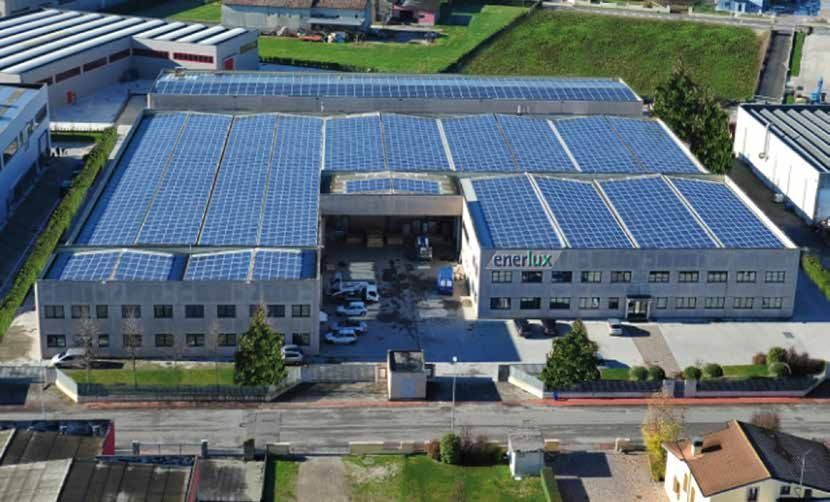
l’aiuto del sole                       help of the sun
  il controllo dell’energia                   energy control
l’energia necessaria per realizzare i   the energy needed to manufacture
nostri prodotti proviene dal nostro      our products originates from our
        impianto fotovoltaico                   photovoltaic plant

             il controllo dell'energia
                   energy control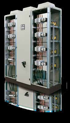
SOMMARIO
                SUMMARY

informazioni
  generali
               INFORMAZIONI TECNICHE                               pag 4
  general      TECHNICAL INFORMATION
information
               CARATTERISTICHE DEI CONDENSATORI                    pag 13
               CHARACTERISTICS OF CAPACITORS

               CONSIDERAZIONI GENERALI                             pag 18
               GENERAL REMARKS

               GUIDA ALLA SCELTA DEL PRODOTTO                      pag 20
               GUIDE TO THE CHOISE OF THE PRODUCT

rifasamento
    fisso      CONDENSATORI MONOFASE                PRM            pag 22
               SINGLE-PHASE CAPACITORS
   fixed
power-factor   CONDENSATORI TRIFASE                 PRT-DPRT       pag 24
               THREE-PHASE CAPACITORS               UTF
                                                    FT-FTE

               APPARECCHIATURE                      CGT            pag 32
               EQUIPMENT                            RGT

rifasamento
automatico     APPARECCHIATURE A PARETE             RG1            pag 36
               WALL-MOUNTED EQUIPMENT               RG2
 automatic
power-factor   APPARECCHIATURE A PAVIMENTO          ERA            pag 40
               FREESTANDING EQUIPMENT

               APPARECCHIATURE CON FILTRI           ERAF           pag 43
               EQUIPMENT WITH FILTERS

componenti     CASSETTI MODULARI                    CT-CTX         pag 48
               MODULAR UNITS                        CTF-CTFX
components     REATTANZE                            RA             pag 52
               REACTORS

               REGOLATORI                           EPF 6/8/12 T   pag 55
               REGULATORS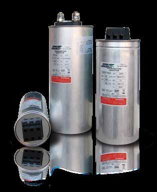
INFORMAZIONI TECNICHE
                                               TECHNICAL INFORMATION

INTRODUZIONE                                                                             INTRODUCTION

Il corretto dimensionamento degli impianti elettrici e delle apparecchiature             Correct design of electrical installations and service equipments permits reducing
utilizzatrici consente una riduzione degli sprechi ma soprattutto una razionale          waste, but above all a rational use of the electrical energy with ensuing optimiza-
utilizzazione dell’energia elettrica, con conseguente ottimizzazione dei costi ad        tion of the correlated costs.
essa correlati.                                                                          A fundamental characteristic of minimizing expenses related to the purchase of
Una prerogativa fondamentale per minimizzare la spesa relativa all’acquisto              energy is to reduce losses, starting from generation and on to distribution and use.
dell’energia è la riduzione delle perdite a partire dalla generazione fino alla di-      Power-factor correction is one of the actions that make it possible to accomplish
stribuzione ed utilizzazione.                                                            substantial energy savings as it:
Il rifasamento è una delle azioni che consentono di ottenere un consistente              - limits energy losses due to the Joule effect along the cables
risparmio energetico in quanto:                                                          - limits drops in voltage along the cables
- limita le perdite di energia per effetto Joule lungo le condutture                     - reduces plant engineering costs for users, making it possible to utilize conductors
- limita le cadute di tensione lungo le condutture                                       with a smaller cross-section
- riduce i costi di realizzazione impiantistica presso le utenze consentendo di          - prevents users from incurring the penalties contained in electrical energy supply
utilizzare conduttori di sezione inferiore.                                              contracts.
- evita all’utente di incorrere nelle penali previste dai contratti di fornitura         This memo therefore sets out to provide an overview of power-factor correction
dell’energia elettrica                                                                   installations, specifying some points of interest; however, it is recommended to
Questa memoria si prefigge quindi lo scopo di offrire una panoramica generale            contact the Enerlux Engineering Department, not only in case of doubt, but also to
sugli impianti di rifasamento, specificando alcuni punti di interesse; tuttavia si       check the choices made for the various components and their design.
consiglia di contattare l’Ufficio Tecnico Enerlux, non solo in caso di dubbi, ma
anche a titolo di verifica in relazione alle scelte effettuate sui vari componenti e
sul loro dimensionamento.

                                                                                         POWER FACTOR
FATTORE DI POTENZA
                                                                                         To comprehend the reasons for the usefulness and need for power factor correc-
Per comprendere i motivi dell’utilità e della necessità del rifasamento verranno         tion, some examples will be illustrated here.
di seguito illustrati alcuni esempi.                                                     Much electrical equipment (especially in the industrial field, such as for example
Molte apparecchiature elettriche, specialmente in campo industriale, come ad             motors, transformers, reactors or power converters), in addition to power known
esempio motori, trasformatori, reattori o convertitori di potenza richiedono             as “active power” (P) capable of translating into work of a mechanical nature, heat,
per il loro funzionamento oltre ad una potenza denominata “potenza attiva”               light, etc., needs power known as “reactive power” (Q) needed to energize magne-
(P) capace di tradursi in lavoro di natura meccanica, termica, luminosa ecc, una         tic circuits.
potenza nota come “potenza reattiva” (Q), necessaria ad eccitare i circuiti ma-          In other words, we can affirm that not all the energy is used to do work, but only the
gnetici.                                                                                 portion relating to active power.
In altri termini si può affermare che non tutta l’energia viene utilizzata per com-      Electric installations must however be designed by taking into consideration power
piere lavoro, ma solamente quella parte relativa alla potenza attiva.                    known as “apparent power” (S), given by the product of voltage and current. To
Il dimensionamento degli impianti elettrici deve tuttavia essere effettuato con-         clarify matters, it is possible to consider the total current to which the apparent
siderando una potenza denominata “potenza apparente” (S), data dal prodotto              power is associated as the vectorial sum of a resistive component IR (component in
della tensione per la corrente. Per chiarire le idee è possibile considerare la cor-     phase with the voltage due to the resistive portion of the load), to which the active
rente totale alla quale è associata la potenza apparente come somma vettoriale           power P is associated, and the inductive current IL (wattless component due to the
di una componente resistiva IR (componente in fase con la tensione dovuta alla           inductive portion of the load), to which the reactive power Q is associated.
parte resistiva del carico) alla quale è associata la potenza attiva P e della corren-   The apparent power S therefore takes account of both the active power P and the
te induttiva IL (componente in quadratura dovuta alla parte induttiva del carico)        reactive power Q. Figure A shows the relationship between active, reactive and ap-
alla quale è associata la potenza reattiva Q.                                            parent power by means of the so-called “power triangle.”
Nella potenza apparente S viene quindi tenuto conto sia dalla potenza attiva P           The relationship between the active power P and the apparent power S is called the
che della potenza reattiva Q. La figura A rappresenta la relazione tra potenza           power factor and is usually indicated as “cosφ”.
attiva, reattiva ed apparente mediante il cosiddetto “triangolo delle potenze”.
Il rapporto fra la potenza attiva P e la potenza apparente S è detto fattore di
potenza ed è abitualmente indicato come “cosφ”.

        4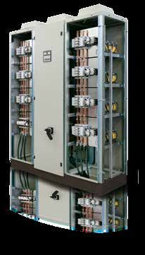
INFORMAZIONI TECNICHE
                                                                           TECHNICAL INFORMATION

         FIG. A

A parità di potenza attiva un carico a basso fattore di potenza causa una mag-       Active power being equal, a load with a low power factor causes a greater call for
giore richiesta di potenza apparente alla rete rispetto ad un carico con fattore     apparent power from the network compared to a load with a higher power factor
di potenza più elevato con conseguente aumento delle cadute di tensione e            with an ensuing increase in voltage drops and, as a result, losses.
di conseguenza delle perdite.                                                        To limit costs related to distribution installation design made depending on servi-
Per contenere i costi relativi ad un dimensionamento degli impianti di distri-       ces with a low power factor, the electricity distribution companies have penalties
buzione effettuato in funzione di utenze a basso fattore di potenza, gli enti        with the aim of discouraging users from drawing too much reactive power from
erogatori dell’energia prevedono penali con lo scopo di scoraggiare l’assor-         the mains, which therefore must be supplied to the load via systems installed on
bimento dalla rete di una quantità eccessiva di potenza reattiva, che quindi         the user’s premises.
deve essere fornita al carico per mezzo di sistemi installati presso l’utilizza-     These systems are in virtually every case composed of static power-factor correc-
tore.                                                                                tion capacitors that, drawing a capacitative current IC staggered 90° in advance
Tali sistemi sono nella quasi totalità dei casi costituiti da condensatori statici   on the phase voltage compensate part of the inductive current IL absorbed by the
di rifasamento che, assorbendo una corrente capacitiva IC sfasata di 90° in          inductive components of the loads. In this way the reactive power absorbed by the
anticipo sulla tensione di fase compensano parte della corrente induttiva IL         user is no longer totally tapped from the mains, but to a certain extent supplied
assorbita dalle componenti induttive dei carichi. In questo modo la potenza          by the capacitor. Figure B shows a power triangle with and without power-factor
reattiva assorbita dall’utilizzatore non è più totalmente prelevata dalla rete,      correction. Notice how adding the capacitor that provides the reactive power QC
ma fornita in una certa misura dal condensatore. In figura B viene mostrato un       causes a decrease in the angle φ and, as a result, an increase in the power factor.
triangolo delle potenze in assenza ed in presenza di rifasamento. Si noti come
l’introduzione del condensatore che fornisce la potenza reattiva QC causi la
diminuzione dell’angolo φ e di conseguenza l’innalzamento del fattore di po-
tenza.

         FIG. B

                                                                                                                                                              5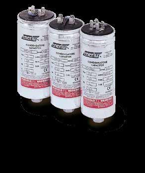
INFORMAZIONI TECNICHE
                                                      TECHNICAL INFORMATION

TIPOLOGIE DI RIFASAMENTO                                                               TYPES OF POWER FACTOR CORRECTION
Il rifasamento può essere realizzato in diverse modalità a seconda delle varie         Power factor correction can be accomplished in different ways depending on the
applicazioni e necessità; le tipologie di rifasamento si possono distinguere in:       various applications and needs. The types of power factor correction can be dif-
                                                                                       ferentiated into:
• Rifasamento distribuito
• Rifasamento centralizzato                                                            • Individual power factor correction
• Rifasamento misto                                                                    • Centralized power factor correction
• Rifasamento per gruppi                                                               • Mixed power factor correction
                                                                                       • Power factor correction per groups
Illustreremo qui di seguito le due principali tipologie di rifasamento.
                                                                                       Here we illustrate the two main types of power factor correction.

RIFASAMENTO DISTRIBUITO                                                                INDIVIDUAL POWER FACTOR CORRECTION

E’ particolarmente adatto ad utenze con carico costante come trasformatori             This is particularly suited for services with a constant load such as transformers
e grossi motori (pompe, ventilatori, mulini ecc.); viene solitamente realizzato        and large motors (pumps, fans, mills etc.). It is usually made in the vicinity of the
nelle vicinanze del carico da rifasare, collegando uno o più condensatori in           load of which to correct the power factor, connecting one or more capacitors in
parallelo.                                                                             parallel.
Nel paragrafo CALCOLO DELLA POTENZA RIFASANTE viene fornito uno stru-                  In the paragraph entitled POWER FACTOR CALCULATION, a tool is given for sizing
mento di dimensionamento per il condensatore da utilizzare per il rifasamen-           the capacitor to use for the power factor correction of motors and transformers.
to di motori e trasformatori.                                                          The fundamental benefits of this method are:
I vantaggi sostanziali di questo metodo sono:                                          • economic as regards installation of the system, since both the load and the
• economici relativamente all’installazione dell’impianto, in quanto sia il cari-          power-factor correction battery work simultaneously. It is therefore possible
    co, sia la batteria di rifasamento lavorano contemporaneamente; è quindi               to avoid installing more control gear and protection systems than the ones
    possibile evitare l’installazione di ulteriori apparecchi di manovra e di siste-       originally envisaged for the load (after correct rating);
    mi di protezione rispetto a quelli previsti originariamente dal carico (previo     • economic as regards operation, since there is a decrease in voltage drops on all
    corretto dimensionamento);                                                             the conductors carrying the current of the load and, as a result, a reduction in
• economici relativamente all’esercizio, in quanto si ottiene diminuzione del-             losses.
    le cadute di tensione in tutti i conduttori percorsi dalla corrente del carico     When the power-factor correction capacitor is permanently connected to the ter-
    e di conseguenza una riduzione delle perdite.                                      minals of a motor, its rated power must be no greater than 90% of the reactive
Quando il condensatore di rifasamento è connesso permanentemente ai                    power absorbed by the motor.
morsetti di un motore, la sua potenza nominale non deve essere superiore al
90% del valore della potenza reattiva assorbita dal motore stesso.

            FIG. C

        6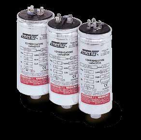
INFORMAZIONI TECNICHE
                                                                              TECHNICAL INFORMATION

RIFASAMENTO CENTRALIZZATO                                                               CENTRALIZED POWER FACTOR CORRECTION

Particolarmente adatto in impianti caratterizzati da varie utenze con tempi di          Particularly suitable for installations with various services having discontinuous uti-
utilizzo discontinui; viene solitamente attuato nelle vicinanze della cabina di tra-    lization times. It is usually implemented close to the transforming cell close to the
sformazione o in vicinanza del quadro generale dell’impianto.                           main switchgear of the installation.
Tale sistema, che viene realizzato mediante l’installazione di più batterie di          This system made by installing several capacitor batteries that switch-in and –out
condensatori inserite o disinserite per mezzo di appositi regolatori automatici         through automatic power factor regulators, is specially flexible since it permits con-
del fattore di potenza, risulta particolarmente flessibile in quanto consente di        tinuous and independent adjusting to a load that changes over time.
adattarsi continuamente ed autonomamente ad un carico che varia nel tempo.              This choice is therefore economically advantageous, especially in large industrial
Questa scelta risulta quindi economicamente vantaggiosa specialmente in                 complexes where the individual power factor correction, due to many users, would
grandi complessi industriali dove il rifasamento distribuito, a causa delle nume-       not be cost effective.
rose utenze, risulterebbe non conveniente.

          FIG. D

CALCOLO DELLA POTENZA RIFASANTE                                                         POWER FACTOR CALCULATION

CALCOLO POTENZA RIFASANTE PER RIFASAMENTO CENTRALIZZATO                                 POWER FACTOR CALCULATION FOR CENTRALIZED POWER FACTOR COR-
                                                                                        RECTION

Per le considerazioni esposte nei paragrafi precedenti, noto il cosφ iniziale           Considering the remarks made in the above paragraphs, knowing the installation’s
dell’impianto e scelto il cosφ’ finale, la potenza reattiva rifasante risulta essere:   initial cosφ and choosing the final cosφ’, the corrected reactive power is:

dove P è il valore medio mensile della potenza attiva assorbita dall’impianto           where P is the mean monthly value of the active power absorbed by the installa-
data da:                                                                                tion given by:

Dove:                                                                                   Where:
Ep è il valore di energia attiva prelevata dalla rete                                   Ep is the value of active energy drawn from the network
h sono le ore di lavoro nell’arco di una giornata                                       h is the number of hours worked in a day
g sono i giorni di lavoro                                                               g is the number of days worked

                                                                                                                                                                    7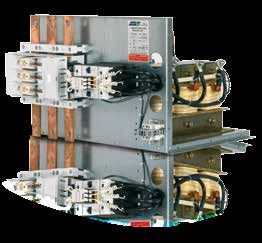
INFORMAZIONI TECNICHE
                                                               TECHNICAL INFORMATION

 cosφ                                                                                    cosφ’ da raggiungere / cosφ’ to reach
iniziale
                   0.9               0.91              0.92              0.93              0.94              0.95              0.96              0.97             0.98               0.99                1
initial
0.45 1.500 1.529 1.559 1.589 1.622 1.656 1.693 1.734 1.781 1.842 1.985
0.46 1.446 1.475 1.504 1.535 1.567 1.602 1.639 1.680 1.727 1.788 1.930
0.47 1.394 1.422 1.452 1.483 1.515 1.549 1.586 1.627 1.675 1.736 1.878
0.48 1.343 1.372 1.402 1.432 1.465 1.499 1.536 1.577 1.625 1.685 1.828
0.49 1.295 1.323 1.353 1.384 1.416 1.450 1.487 1.528 1.576 1.637 1.779
0.5  1.248 1.276 1.306 1.337 1.369 1.403 1.440 1.481 1.529 1.590 1.732
0.51 1.202 1.231 1.261 1.291 1.324 1.358 1.395 1.436 1.484 1.544 1.687
0.52 1.158 1.187 1.217 1.247 1.280 1.314 1.351 1.392 1.440 1.500 1.643
0.53 1.116 1.144 1.174 1.205 1.237 1.271 1.308 1.349 1.397 1.458 1.600
0.54 1.074 1.103 1.133 1.163 1.196 1.230 1.267 1.308 1.356 1.416 1.559
0.55 1.034 1.063 1.092 1.123 1.156 1.190 1.227 1.268 1.315 1.376 1.518
0.56 0.995 1.024 1.053 1.084 1.116 1.151 1.188 1.229 1.276 1.337 1.479
0.57 0.957 0.986 1.015 1.046 1.079 1.113 1.150 1.191 1.238 1.299 1.441
0.58 0.920 0.949 0.979 1.009 1.042 1.076 1.113 1.154 1.201 1.262 1.405
0.59 0.884 0.913 0.942 0.973 1.006 1.040 1.077 1.118 1.165 1.226 1.368
0.6  0.849 0.878 0.907 0.938 0.970 1.005 1.042 1.083 1.130 1.191 1.333
0.61 0.815 0.843 0.873 0.904 0.936 0.970 1.007 1.048 1.096 1.157 1.299
0.62 0.781 0.810 0.839 0.870 0.903 0.937 0.974 1.015 1.062 1.123 1.265
0.63 0.748 0.777 0.807 0.837 0.870 0.904 0.941 0.982 1.030 1.090 1.233
0.64 0.716 0.745 0.775 0.805 0.838 0.872 0.909 0.950 0.998 1.058 1.201
0.65 0.685 0.714 0.743 0.774 0.806 0.840 0.877 0.919 0.966 1.027 1.169
0.66 0.654 0.683 0.712 0.743 0.775 0.810 0.847 0.888 0.935 0.996 1.138
0.67 0.624 0.652 0.682 0.713 0.745 0.779 0.816 0.857 0.905 0.966 1.108
0.68 0.594 0.623 0.652 0.683 0.715 0.750 0.787 0.828 0.875 0.936 1.078
0.69 0.565 0.593 0.623 0.654 0.686 0.720 0.757 0.798 0.846 0.907 1.049
0.7  0.536 0.565 0.594 0.625 0.657 0.692 0.729 0.770 0.817 0.878 1.020
0.71 0.508 0.536 0.566 0.597 0.629 0.663 0.700 0.741 0.789 0.849 0.992
0.72 0.480 0.508 0.538 0.569 0.601 0.635 0.672 0.713 0.761 0.821 0.964
0.73 0.452 0.481 0.510 0.541 0.573 0.608 0.645 0.686 0.733 0.794 0.936
0.74 0.425 0.453 0.483 0.514 0.546 0.580 0.617 0.658 0.706 0.766 0.909
0.75 0.398 0.426 0.456 0.487 0.519 0.553 0.590 0.631 0.679 0.739 0.882
0.76 0.371 0.400 0.429 0.460 0.492 0.526 0.563 0.605 0.652 0.713 0.855
0.77 0.344 0.373 0.403 0.433 0.466 0.500 0.537 0.578 0.626 0.686 0.829
0.78 0.318 0.347 0.376 0.407 0.439 0.474 0.511 0.552 0.599 0.660 0.802
0.79 0.292 0.320 0.350 0.381 0.413 0.447 0.484 0.525 0.573 0.634 0.776
0.8  0.266 0.294 0.324 0.355 0.387 0.421 0.458 0.499 0.547 0.608 0.750
0.81 0.240 0.268 0.298 0.329 0.361 0.395 0.432 0.473 0.521 0.581 0.724
0.82 0.214 0.242 0.272 0.303 0.335 0.369 0.406 0.447 0.495 0.556 0.698
0.83 0.188 0.216 0.246 0.277 0.309 0.343 0.380 0.421 0.469 0.530 0.672
0.84 0.162 0.190 0.220 0.251 0.283 0.317 0.354 0.395 0.443 0.503 0.646
0.85 0.135 0.164 0.194 0.225 0.257 0.291 0.328 0.369 0.417 0.477 0.620
0.86 0.109 0.138 0.167 0.198 0.230 0.265 0.302 0.343 0.390 0.451 0.593
0.87 0.082 0.111 0.141 0.172 0.204 0.238 0.275 0.316 0.364 0.424 0.567
0.88 0.055 0.084 0.114 0.145 0.177 0.211 0.248 0.289 0.337 0.397 0.540
0.89 0.028 0.057 0.086 0.117 0.149 0.184 0.221 0.262 0.309 0.370 0.512
0.9  0.000 0.029 0.058 0.089 0.121 0.156 0.193 0.234 0.281 0.342 0.484
0.91		 0.000     0.030 0.060 0.093 0.127 0.164 0.205 0.253 0.313 0.456
0.92			 0.000          0.031 0.063 0.097 0.134 0.175 0.223 0.284 0.426
0.93				 0.000               0.032 0.067 0.104 0.145 0.192 0.253 0.395
0.94					 0.000                    0.034 0.071 0.112 0.160 0.220 0.363
0.95						 0.000                         0.037 0.078 0.126 0.186 0.329
0.96							 0.000                              0.041 0.089 0.149 0.292
0.97								                                   0.000 0.048 0.108 0.251
0.98									                                        0.000 0.061 0.203
0.99										                                             0.000 0.142
1											                                                     0.000

         TAB. 1
     La Tabella 1 fornisce i valori del coefficiente “K” mediante il quale è possibile ottenere la potenza reattiva QC nota la potenza attiva del carico, il cosφ dell’impianto in assenza di rifasamento e scelto
     il cosφ’ che si desidera ottenere.
     Table 1 gives the values of the coefficient “K” with which it is possible to obtain the reactive power QC, knowing the active power of the load and the installation’s cosφ with no power factor correction
     and choosing the cosφ’ you want to obtain.

     8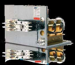
INFORMAZIONI TECNICHE
                                                                                        TECHNICAL INFORMATION

ESEMPIO 1 (considerando la delibera AEEG 180/2013/R/EEL):                                            EXAMPLE 1:
Determinazione della potenza capacitiva necessaria a rifasare a cosφ’ 0,92                           Calculating the capacitative power needed for p.f. correction to cosφ’ 0.92 of
un impianto che assorbe 132 kW, con cosφ in assenza di rifasamento pari a                            an installation drawing 132 kW, with a cosφ of 0.6 with no power factor cor-
0,6.                                                                                                 rection.

132 x 1,005 = 132,66 kvar = 135 kvar.                                                                132 x 1.005 = 132.66 kvar = 135 kvar.

La potenza apparente richiesta varierà quindi                                                        The apparent power required will then vary

ESEMPIO 2 (considerando la delibera AEEG 180/2013/R/EEL):                                            EXAMPLE 2:
Determinazione della potenza capacitiva necessaria a rifasare a cosφ’ 0,95                           Calculating the capacitative power necessary for p.f. correction to cosφ’ 0.95
un impianto che assorbe 630 kW, con cosφ in assenza di rifasamento pari a                            of an installation drawing 630 kW, with a cosφ of 0.72 with no power factor
0,72                                                                                                 correction.

630 x 0,635 = 400,05 kvar = 400 kvar.                                                                630 x 0.635 = 400.05 kvar = 400 kvar.

La potenza apparente richiesta varierà quindi                                                        The apparent power required will then vary

CALCOLO POTENZA RIFASANTE PER MOTORI ASINCRONI TRIFASE                                               POWER FACTOR CALCULATION FOR THREE-PHASE ASYNCHRONOUS MO-
Come anticipato nel paragrafo relativo al “RIFASAMENTO DISTRIBUITO”,                                 TORS
quando il condensatore di rifasamento è connesso permanentemente ai                                  As mentioned under the heading “INDIVIDUAL POWER FACTOR CORRECTION”,
morsetti del motore,la sua potenza nominale non deve essere superiore al                             when the power-factor correction capacitor is permanently connected to the
90% del valore della potenza reattiva assorbita dal motore stesso.                                   terminals of a motor, its rated power must be no greater than 90% of the reac-
Si ha quindi che:                                                                                    tive power absorbed by the motor. We therefore have:

Nella quale con Un si indica la tensione nominale di alimentazione, e con I0 la                      Where Un is the rated power supply voltage and I0 the no load current of the
corrente a vuoto del motore, che, con buona approssimazione, corrisponde                             motor that, to a good degree of approximation, corresponds to the component
alla componente della corrente relativa alla potenza reattiva assorbita dal                          of the current relating to the reactive power absorbed by the motor (wattless
motore stesso (componente in quadratura o corrente magnetizzante).                                   component or magnetizing current).

Nella tabella 2 vengono indicati i valori di potenza reattiva consigliati per il                     Table 2 gives the recommended reactive power values for power factor correc-
rifasamento di motori asincroni trifase funzionanti a pieno carico.                                  tion of three-phase asynchronous motors running on full load.

                                                                                                                          Kvar
                POTENZA MOTORE
                 MOTOR POWER                                     3000                         1500                        1000                         750          500
                                                                 GIRI/MIN                    GIRI/MIN                     GIRI/MIN                    GIRI/MIN     GIRI/MIN
          HP                          kW                          R.P.M.                      R.P.M.                       R.P.M.                      R.P.M.       R.P.M.
          3/4                         0.55                          -                           -                           0.5                            0.5
            1                         0.73                         0.5                         0.5                          0.6                            0.6
            2                         1.47                         0.8                         0.8                           1                              1
            3                         2.21                          1                           1                           1.2                            1.6
            5                         3.68                         1.6                         1.6                           2                             2.5
            7                         5.15                          2                           2                           2.5                             3
           10                         7.36                          3                           3                            4                              4        5
           15                          11                           4                           5                            5                              6        6
           30                         22.1                         10                          10                           10                             12        15
           50                          36,                         15                          20                           20                             25        25
          100                          73,                         25                          30                           30                             30        40
          150                         110                          30                          40                           40                             50        60
          200                         147                          40                          50                           50                             60        70
          250                         184                          50                          60                           60                             70        80

         TAB. 2
        Tabella per la scelta della Potenza dei Condensatori (in kvar) necessaria per rifasamento su Motori Asincroni trifase funzionanti a pieno carico
        Table for choosing the Power of Capacitors (in kvar) needed for power factor correction on three-phase Asynchronous Motors running on full load

                                                                                                                                                                          9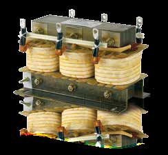
INFORMAZIONI TECNICHE
                                                                TECHNICAL INFORMATION

CALCOLO POTENZA RIFASANTE PER TRASFORMATORI                                                              POWER FACTOR CALCULATION FOR TRANSFORMERS

Per quanto concerne i trasformatori, nei casi in cui gli stessi possano funzio-                          As regards transformers, in cases where they can work with no load (disconti-
nare a vuoto (cicli discontinui), esiste la necessità di rifasare la potenza as-                         nuous cycles), there is the need to correct the power factor with no load or a limi-
sorbita a vuoto o con carico limitato inserendo in parallelo al trasformatore                            ted load by putting a capacitor bank in parallel with the transformer; the purpose
una batteria di condensatori; i condensatori hanno lo scopo di compensare                                of the capacitors is to compensate the magnetizing current of the transformer
la corrente magnetizzante del trasformatore che serve a generare il campo                                used to generate the magnetic field needed for its operation.
magnetico necessario per il suo funzionamento.                                                           Table 3 gives the recommended reactive power values to power factor correct
Nella tabella 3 vengono indicati i valori di potenza reattiva consigliati per il                         MV/LV transformers according to the primary voltage.
rifasamento di trasformatori MT/BT in funzione della tensione primaria.

                        EFFETTI DELLE ARMONICHE                                       TRASFORMATORI IN OLIO                                      TRASFORMATORI IN RESINA
                          POWER TRANSFOMER                                              OIL TRANSFORMER                                            RESIN TRANSFORMER
                                   KVA                                                         Kvar                                                        Kvar
                                       10                                                           1                                                              1,5
                                       20                                                           2                                                              1,7
                                       50                                                           4                                                               2
                                       75                                                           5                                                              2,5
                                      100                                                           5                                                              2,5
                                      160                                                           7                                                               4
                                      200                                                          7,5                                                              5
                                      250                                                           8                                                              7,5
                                      315                                                          10                                                              7,5
                                      400                                                         12,5                                                              8
                                      500                                                          15                                                              10
                                      630                                                         17,5                                                            12,5
                                      800                                                          20                                                              15
                                     1000                                                          25                                                             17,5
                                     1250                                                          30                                                              20
                                     1600                                                          35                                                              22
                                     2000                                                          40                                                              25
                                     2500                                                          50                                                              35
                                     3150                                                          60                                                              50
           TAB. 3
        Tabella per la scelta della Potenza dei Condensatori (in kvar) per rifasamento di Trasformatori MT/BT in funzione della tensione primaria
        Table for choosing the Power Values of the Capacitors (en kvar) for power factor correction of the MV/LV transformers according to the primary voltage.

EFFETTI DELLE ARMONICHE                                                                                  EFFECTS OF HARMONICS
Gli impianti elettrici sono frequentemente interessati in modo più o meno                                Electrical installations are frequently affected to a greater or lesser degree by in-
rilevante da disturbi provenienti dalle reti di distribuzione e dai carichi non                          terference from distribution networks and from the non-linear loads they supply,
lineari da essi stessi alimentati, che possono facilmente causare malfunzio-                             which can easily cause malfunctioning and faults.
namenti e guasti.                                                                                        Some of the most common problems comprise deformation of the current and
Tra i disturbi più diffusi spiccano la deformazione delle forme d’onda di cor-                           voltage wave shapes, i.e. the presence of multiple frequency components of the
rente e di tensione ovvero la presenza di componenti a frequenza multiple                                pure wave.
della fondamentale.                                                                                      The origin of the current distortions may depend on:
L’origine delle distorsioni della corrente può dipendere da:                                             - non-linear loads (semiconductor rectifiers commonly used in battery chargers,
- carichi non lineari (raddrizzatori a semiconduttori largamente diffusi in carica                       galvanotechnical electrolysis rectifiers, operating mechanisms)
batterie, raddrizzatori per elettrolisi galvanotecnica, azionamenti)                                     - arc furnaces
- forni ad arco                                                                                          - large electric welding installations.
- grossi impianti di saldatura elettrica.                                                                The origin of the voltage distortions may on the other hand be connected to:
L’origine delle distorsioni della tensione può invece essere legata a:                                   - phenomena of saturation (transformers)
- fenomeni di saturazione (trasformatori)                                                                - deformation of the voltage wave of generators.
- deformazione dell’onda di tensione dei generatori.                                                     The most obvious and damaging consequences of the voltage and current defor-
Le conseguenze più evidenti e più dannose delle deformazioni della tensione                              mation are an increase in losses and the risk of phenomena of resonance occur-
e della corrente sono l’aumento delle perdite ed il pericolo di insorgenza di                            ring in electrical equipment and machines.
fenomeni di risonanza nelle macchine e nelle apparecchiature elettriche.                                 As regards the capacitors, the current and voltage harmonics cause an increase in
Per quanto riguarda i condensatori, le armoniche di corrente e di tensione                               losses that can lead to the safety device tripping.
provocano un aumento delle perdite, che possono portare all’intervento del                               The transformers and cables may suffer damage due to the conductors overhe-
dispositivo di protezione.                                                                               ating because of the Joule effect and the increase in additional losses in the ma-
I trasformatori e i cavi possono subire danneggiamenti a causa di un eccessivo                           gnetic circuits caused by the components at higher frequencies.
riscaldamento dei conduttori per effetto Joule e per l’incremento delle per-
dite addizionali nei circuiti magnetici causato dalle componenti a frequenze
maggiori.

      10
INFORMAZIONI TECNICHE
TECHNICAL INFORMATION
La tensione di rete distorta dalle correnti non sinusoidali assorbite dai carichi The mains voltage distorted by the non-sinusoidal currents drawn by the contami-
inquinanti può, a sua volta, dare origine ad armoniche di corrente in compo- nating loads can, in its turn, give rise to current harmonics in linear components,
nenti di per sé lineari, come condensatori e resistori ed in macchine elettriche, such as capacitors and resistors and in electric machinery, such as transformers
quali trasformatori e motori nei quali si inducono perdite e vibrazioni mecca- and motors in which losses and mechanical vibration are induced.
niche. According to Fourier, every non-sinusoidal periodical phenomenon can be obtai-
Secondo Fourier, ogni fenomeno periodico non sinusoidale è ottenibile come ned as the sum of sinusoidal components, each one of the appropriate amplitude
somma di più componenti sinusoidali, ognuna di ampiezza opportuna e con and with whole multiple frequency of the pure wave, having frequency equal to
frequenza multipla intera dell’onda fondamentale, caratterizzata da una fre- that of the initial distorted periodical wave.
quenza pari a quella dell’onda periodica distorta di partenza. The presence of harmonics in a network in which capacitors are installed causes
La presenza di armoniche in una rete nella quale sono installati condensatori a current overload on this type of component given by the following equation:
provoca su questo tipo di componente un sovraccarico di corrente dato dalla
seguente equazione:
dove where
I1 = Corrente alla frequenza dell’onda fondamentale I1 = Current at the frequency of the pure wave
S = Somma di tutte le correnti armoniche a partire dalla 2a fino all’ n-esima. S = Sum of all the harmonic currents starting from the 2nd until the nth.
In figura E si mostra una corrente di forma quadra tipica di un carico non Figure E shows a current with the typical square shape of a non-linear load,
lineare,della quale si fornisce anche la scomposizione per mezzo della serie whose breakdown is also given by means of the Fourier series limited to the
di Fourier limitata al settimo ordine. seventh order.
ONDA QUADRA ORIGINARIA
PRIMARY SQUARE WAVE
ONDA FONDAMENTALE
PURE WAVE
ONDA DI 2a ARMONICA
2nd HARMONIC WAVE
ONDA DI 4a ARMONICA
4th HARMONIC WAVE
ONDA DI 5a ARMONICA
5th HARMONIC WAVE
ONDA DI 7a ARMONICA
7th HARMONIC WAVE
FIG. C
Da quanto sopra detto si può facilmente dedurre che una corrente distorta From the above we may easily infer that a distorted current with a frequency of
con frequenza pari a 50 Hz può essere vista come somma di una corrente 50 Hz can be seen as the sum of a sinusoidal current at 50 Hz and other currents
sinusoidale a 50 Hz e di altre correnti con frequenze multiple ( ad es. 100- with multiple frequencies (e.g., 100-150-200-250 Hz-etc.).
150-200-250 Hz-ecc.). When there are distortions, it is strongly recommended not to do the power fac-
In presenza di distorsioni è vivamente sconsigliato il rifasamento eseguito tor correction with just the aid of capacitors as they can trigger phenomena of
con il solo ausilio di condensatori, in quanto possono innescarsi fenomeni parallel resonance with the network, leading to an amplification of the existing
di risonanza parallelo con la rete che portano all’amplificazione delle armo- harmonics. It is therefore necessary to run a thorough check targeted at iden-
niche già esistenti; è quindi necessario eseguire un’accurata verifica mirata tifying the resonance frequency “fr” of the tuned circuit composed of the power
ad individuare la frequenza di risonanza “fr” del circuito accordato costituito factor correction capacitor and the mainly reactive impedance of the network.
dal condensatore di rifasamento e dall’impedenza prevalentemente reattiva For this purpose, the following formula is helpful:
della rete. Allo scopo è utile la seguente formula:
11INFORMAZIONI TECNICHE
TECHNICAL INFORMATION
dove where
f1 è la frequenza dell’onda fondamentale f1 is the frequency of the pure wave
SCC è la potenza di corto circuito della rete (espressa in VA) SCC is the short-circuit power of the network (expressed in VA)
QC è la potenza reattiva del condensatore o della Batteria di condensatori QC is the reactive power of the capacitor or of the Capacitor bank (expressed in
(espressa in var) var)
Le soluzioni utilizzate dalla Enerlux per evitare tali inconvenienti sono costi- The solutions utilized by Enerlux to avoid this trouble consist of using blocking
tuite dall’impiego di reattanze di blocco capaci di proteggere i condensatori reactors capable of protecting the capacitors and enabling correct power factor
e consentire un corretto rifasamento dell’impianto; il loro principio di fun- correction of the installation. Their working principle consists of shifting the reso-
zionamento è quello di spostare la frequenza di risonanza dell’impianto al di nance frequency of the installation under the harmonic of a lower magnitude so
sotto dell’armonica di ordine più basso in modo tale da evitare l’innesco di as to avoid triggering phenomena of resonance.
fenomeni di risonanza. The blocking reactors are normally calculated to be tuned with the capacitor on a
Le reattanze di blocco sono normalmente calcolate per accordarsi con il con- frequency usually varying between 134 and 210 Hz.
densatore su di una frequenza che solitamente varia tra i 134 ai 210 Hz. The parameter quantifying the harmonic load of the current is called the factor of
Il parametro che quantifica il contenuto armonico della corrente è detto fat- distortion or THD, defined as follows:
tore di distorsione o THD definito come segue:
dove: where:
I1 è il valore efficace della corrente alla frequenza dell’onda fondamentale I1 is the r.m.s. value of the current at the frequency of the pure wave
In è il valore efficace della generica corrente armonica di ordine n. In is the r.m.s. value of the generic current harmonic of magnitude No.
Alla luce di quanto sopra esposto è consigliabile una corretta analisi della rete In the light of the above, it is recommended to analyse the network correctly
in presenza di determinati tipi di carico prima di effettuare la scelta del tipo di when there are certain kinds of load before choosing the type of power factor
rifasamento; consigliamo pertanto di contattare l’Ufficio Tecnico Enerlux che correction. We therefore recommended you contact the Enerlux Engineering
vi potrà aiutare e guidare nella scelta dell’apparecchiatura adeguata. Department that will be able to help and guide you in choosing the appropriate
equipment.
12CARATTERISTICHE DEI CONDENSATORI IN POLIPROPILENE
METALLIZATO AD ALTO GRADIENTE
CHARACTERISTICS OF CAPACITORS MADE OF METALIZED
POLYPROPYLENE FILM AT HIGH GRADIENT
TECNOLOGIA COSTRUTTIVA CONSTRUCTION TECHNOLOGY
I condensatori di rifasamento realizzati dalla Enerlux per applicazioni in bassa The power-factor correction capacitors made by Enerlux for low-voltage applica-
tensione sono condensatori sia trifase che monofase, del tipo autorigenera- tions are both three-phase and single-phase capacitors, of the self-healing type,
bili, costituiti da elementi monofase realizzati in film di polipropilene metal- composed of single-phase elements made of a metalized polypropylene film at
lizzato ad alto gradiente che permette di migliorare in modo consistente le high gradient that permits to improve notably capacitor duty (see Figure F). The
prestazioni del condensatore (vedi figura F); l’elemento è “a secco”, in quanto element is “dry” as it is not impregnated with oil, but externally isolated with a
non impregnato in olio ma isolato esternamente da una speciale mescola die- non-toxic dielectric mix, with no PCB or PCT.
lettrica atossica, priva di PCB e PCT. This mix ensures great reliability for the capacitor from a mechanical point of
Questa mescola garantisce al condensatore un’estrema affidabilità dal punto view (insensitive to vibration) and from an electrical point of view (isolation from
di vista meccanico (insensibilità alle vibrazioni) e dal punto di vista elettrico earth further guaranteed).
(isolamento verso massa maggiormente garantito).
1 ELEMENTO CAPACITIVO
CAPACITIVE ELEMENT
2 FILM IN PROPILENE METALLIZZATO (SOLO SU UN LATO)
METALIZED POLYPROPYLENE FILM (ON ONE SIDE ONLY)
3 BORDO LIBERO DA METALLIZZAZIONE
EDGE FREE FROM METALLIZATION
4 ZONA DI CONTATTO
CONTACT AREA
FIG. F
Gli elementi sono inseriti in custodia cilindrica di alluminio estruso, con codolo The elements are put in an extruded aluminium cylindrical can, with fixing spigot
di fissaggio M12 x 12 mm. M12 x 12 mm.
La chiusura del condensatore viene realizzata tramite bordatura della custo- The capacitor is closed with the can bending on the self-extinguishing fibreglass-
dia sulla basetta in nylon rinforzato con fibra di vetro autoestinguente (classe reinforced nylon strip (class V2 according to UL 94 standards), for PRM series and
V2 seconde le norme UL 94), per la serie PRM e disco acciaio per la serie PRT, steel lids for PRT series, ensuring perfect air and water tightness.
garantendo una perfetta ermeticità. The capacitors are equipped with external discharge resistors.
I condensatori sono dotati di resistenze di scarica esterne. Main characteristics of these capacitors:
Caratteristiche principali di questi condensatori: - thanks to this new metallization type having a variable thickness, grant a better
- grazie al nuovo tipo di metallizzazione con spessore variabile un’autorigena- selfhealing at short circuits between the plates
ribilità migliore al verificarsi di cortocircuiti fra le armature - reduction of size due to the increase of specific power (kvar/dm3)
- riduzione delle dimensioni dovuta all’aumento della potenza specifica (kvar/ - more reliability in case of continuous and transient overvoltages
dm3) All Enerlux capacitors are equipped with an overpressure disconnecting safety
- più affidabilità in caso di sovratensioni continuative e transitorie device (see following paragraph).
Tutti i condensatori Enerlux, sono dotati di dispositivo di protezione a interru- Having equal active power, a load with a low power factor, causes a greater call
zione per sovrapressione (vedi paragrafo a seguire). of apparent power from the network compared to a load with a higher power
A parità di potenza attiva un carico a basso fattore di potenza causa una mag- factor with an ensuing increase in voltage drops and, as a result, losses.
giore richiesta di potenza apparente alla rete rispetto ad un carico con fattore
di potenza più elevato con conseguente aumento delle cadute di tensione e
di conseguenza delle perdite.
13CARATTERISTICHE DEI CONDENSATORI
CHARACTERISTICS OF CAPACITORS
Per contenere i costi relativi ad un dimensionamento degli impianti di distri- To limit costs related to distribution installation rating made depending on users
buzione effettuato in funzione di utenze a basso fattore di potenza, gli enti with a low power factor, the electricity distribution companies have penalties
erogatori dell’energia prevedono penali con lo scopo di scoraggiare l’assor- with the aim of discouraging users from absorbing too much reactive power from
bimento dalla rete di una quantità eccessiva di potenza reattiva, che quindi the mains, which therefore must be supplied to the load via systems installed on
deve essere fornita al carico per mezzo di sistemi installati presso l’utilizza- the user’s premises.
tore. These systems are in virtually every case composed of static power-factor correc-
Tali sistemi sono nella quasi totalità dei casi costituiti da condensatori statici tion capacitors that, drawing a capacitative current IC staggered 90° in advance
di rifasamento che, assorbendo una corrente capacitiva IC sfasata di 90° in on the phase voltage compensate part of the inductive current IL absorbed by the
anticipo sulla tensione di fase compensano parte della corrente induttiva IL inductive components of the loads. In this way the reactive power absorbed by
assorbita dalle componenti induttive dei carichi. In questo modo la potenza the user is no longer totally kept by the mains, but to a certain extent supplied
reattiva assorbita dall’utilizzatore non è più totalmente prelevata dalla rete, by the capacitor. Figure B shows a power triangle with and without power-factor
ma fornita in una certa misura dal condensatore. In figura B viene mostrato un correction. Notice how adding the capacitor that provides the reactive power QC
triangolo delle potenze in assenza ed in presenza di rifasamento. Si noti come causes a decrease in the angle φ and, as a result, an increase in the power factor.
l’introduzione del condensatore che fornisce la potenza reattiva QC causi la
diminuzione dell’angolo φ e di conseguenza l’innalzamento del fattore di po-
tenza.
CURVE CARATTERISTICHE DEI CONDENSATORI IN FILM DI CHARACTERISTIC CURVES OF CAPACITORS IN METALLIZED
POLIPROPILENE METALLIZZATO POLYPROPYLENE FILM
Variazioni della Costante Dielettrica del Film metallizzato Costante dielettrica
in funzione della Temperatura Dielectric constant
Change in the Dieletric Costant of the metallized Film in
relation to Temperature
Temperatura - Temperature
Variazioni dell’Angolo di Perdita del Film metallizzato in Angolo di perdita
funzione della Temperatura Loss angle
Change in the Loss Angle of the metallized Film in relation
to Temperature
Temperatura - Temperature
14CARATTERISTICHE DEI CONDENSATORI
CHARACTERISTICS OF CAPACITORS
DISPOSITIVO DI PROTEZIONE A INTERRUZIONE PER
OVERPRESSURE DISCONNECTING SAFETY DEVICE
SOVRAPRESSIONE
L’utilità di questa protezione sui condensatori di bassa tensione, è quella di The usefulness of this protection on low-voltage capacitors is the immediate
interrompere immediatamente il circuito di alimentazione alla fine della vita switch of the power supply circuit at the end of the capacitor’s life and in the
del condensatore stesso e in caso di guasto per sovratensioni eccessive. event of a fault due to excessive overvoltage.
Questa interruzione non provoca esplosioni della custodia o bruciature e This break causes no explosion nor burning of the can and keeps the features of
mantiene inalterate le caratteristiche di tenuta dielettrica verso massa e di the dielectric seal from earth and air and water tightness unchanged. The recur-
ermeticità; il ripetersi delle evaporazioni della metallizzazione generatasi du- rence of evaporation of the metallization generated during self-healing causes
rante l’autorigenerazione sviluppa nel tempo una sovrapressione interna che an internal overpressure in time that causes the can to rise with the device then
provoca l’innalzamento della custodia con successiva sconnessione del dispo- getting disconnected from the power supply.
sitivo dall’alimentazione. Figure G shows the working principle.
In figura G si mostra il principio di funzionamento.
Prima - Before Dopo - After
Connesso - Connected Sconnesso - Disconnected
FIG. G
CONDIZIONI DI SERVIZIO CONDITIONS OF SERVICE
Il condensatore di rifasamento è un componente elettrico che, al termine di The power-factor correction capacitor is an electrical component that, at the end
un periodo di BURN IN e dei vari test eseguiti presso la Enerlux, può essere of a period of BURN IN and of the various tests performed by Enerlux, can be in-
installato in vari tipi di impianti caratterizzati da varie condizioni di esercizio. stalled in various kinds of installations featuring various conditions of operation.
E’ quindi di fondamentale importanza definire ed identificare le condizioni in It is therefore extremely important to define and identify the possible operating
cui potrà operare, onde evitare alterazioni nel suo funzionamento e per pre- conditions to prevent any alteration in its operation and any shortening of its
venirne la riduzione della vita. service life.
I principali parametri relativi al servizio che devono essere verificati sono: The main service parameters that must be checked are:
- Corrente nominale - Rated current
- Corrente di picco - Peak current
- Presenza di armoniche - Presence of harmonics
- Tensione nominale - Rated voltage
- Tensione residua - Residual voltage
- Temperatura - Temperature
15CARATTERISTICHE DEI CONDENSATORI
CHARACTERISTICS OF CAPACITORS
CORRENTE CURRENT
I condensatori sono dimensionati per un funzionamento con correnti perma- The capacitors are rated for operating with permanent currents up to 1.3 In and
nenti fino a 1,3 In, e con correnti pari a 1,5 In nel caso in cui il condensatore with currents of 1.5 In if the capacitor has a capacity with a tolerance of +10%,
presenti una capacità con tolleranza del +10%, in caso di presenza di armoni- if there are harmonics and with overvoltages of 10%.
che e con sovratensioni del 10%. It is therefore necessary to rate all the cables, contactors and equipment in rela-
Occorre pertanto dimensionare in funzione di una corrente di 1,5 In tutti i tion to a current of 1.5 In to prevent these components overheating or breaking.
cavi, i teleruttori e le apparecchiature in modo da evitare surriscaldamenti o Protection fuses must be of delayed type and designed at 1.8÷2 In.
rotture di questi componenti. I fusibili a protezione devono essere del tipo
ritardato e dimensionati a 1.8÷2 In.
CORRENTE DI PICCO PEAK CURRENT
Poiché i condensatori sono caratterizzati da basse perdite causano, all’atto Since capacitors are characterized by low losses, at insertion time they cause an
dell’inserzione, un picco di corrente molto elevato, fino a 200 In, soprattutto extremely high current peak, up to 200 In, especially in instrument panels with a
nei quadri a più gradini, nei quali possono esistere condensatori già carichi. number of steps where there may be capacitors that are already charged.
E’ importante quindi, per evitare danni prematuri ai condensatori ed agli ap- It is therefore important, in order to avoid prematurely damaging the capacitors
parecchi di manovra, l’impiego di teleruttori muniti di reattanze di limitazio- and control gear, to use contactors fitted with in-rush peak current limiting
ne del picco di corrente all’inserzione; la corrente di inserzione deve essere reactors; the in-rush current must be limited to 100 In.
limitata ad un valore di 100 In.
ARMONICHE HARMONICS
Una delle condizioni fondamentali per il corretto funzionamento dei conden- One of the fundamental conditions for the capacitors to work properly is that of
satori, è quello di verificare l’eventuale presenza di armoniche nella rete, per checking harmonics in the network, to prevent distortion of the pure wave sha-
evitare che le distorsioni della forma d’onda fondamentale ed i sovraccarichi pe and the overloading caused by the harmonics, that could damage installed
prodotti dalle armoniche danneggino le apparecchiature installate. equipment.
È quindi indispensabile verificare se nella rete esistono carichi non lineari It is therefore indispensable to check whether the network contains non-linear
che iniettano armoniche nella rete; nel caso in cui vi sia la presenza di tali loads that put harmonics into the network; if there is any such equipment, it
apparecchiature è opportuno eseguire una precisa misurazione tramite un is wise to make an exact measurement using a harmonics analyser or ask for
analizzatore di armoniche oppure chiedendo assistenza all’Ufficio tecnico assistance of Enerlux Engineering Department that will make the appropriate
della Enerlux che provvederà alle opportune verifiche guidandovi nella checks and guide you in the choice of the most appropriate product.
scelta del prodotto più appropriato.
TENSIONE VOLTAGE
I condensatori sono dimensionati per un funzionamento ad un livello di ten- The capacitors are rated to work at a level of voltage in compliance with Italian
sione conforme alle vigenti normative italiane CEI EN 60831-1/2 e alle norme CEI EN 60831-1/2 and international IEC 831-1/2 standards as stated in table
internazionali IEC 831-1/2 secondo quanto riportato nella tabella n. 4: no. 4:
TENSIONE SENZA ARMONICHE DURATA MASSIMA OSSERVAZIONI
VOLTAGE WITHOUT HARMONICS MAXIMUM DURATION REMARKS
continua Massimo valore medio durante un qualsiasi periodo di energizzazione
Un
continued Highest average value during any period of capacitor energization
8 h ogni 24 h Regolazioni e fluttuazioni della tensione di rete
1,1 Un
8 h every 24 h System voltage regulation and fluctuations
30 min ogni 24 h Regolazioni e fluttuazioni della tensione di rete
1,15 Un
30 min every 24 h System voltage regulation and fluctuations
Aumento di tensione a basso carico
1,2 Un 5 min
Voltage rise at light load
Aumento di tensione a basso carico
1,3 Un 1 min
Voltage rise at light load
TAB. 4
E’ importante segnalare che sovratensioni maggiori di 1.15 Un non possono verificarsi per non più di 200 volte nella vita di un Condensatore.
It is important to note that overvoltages greater than 1.15 Un may not occur for no more than 200 times in the life of a Capacitor.
16CARATTERISTICHE DEI CONDENSATORI
CHARACTERISTICS OF CAPACITORS
Spesso vengono utilizzati condensatori con tensione nominale maggiore ri- Capacitors are often used with a greater rated voltage than the mains voltage to
spetto alla tensione di rete per evitare che sovratensioni di varie origini (ad prevent overvoltages of various origin (for example, small harmonic components)
esempio presenza di piccole componenti armoniche) possano provocarne la being able to damage the dielectric. In cases such as this, it is however necessary
rottura del dielettrico. In casi come questo occorre tuttavia prestare attenzio- to pay attention to the fact that the rating of the capacitor is no longer equiva-
ne al fatto che la potenza nominale del condensatore non equivale più alla lent to the power output as it is powered at lower voltages.
potenza resa in quanto alimentato a tensioni più basse.
La potenza reattiva generata vale quindi: The generated reactive power is therefore:
dove: where:
Ur è la tensione alla quale viene alimentato il condensatore Ur is the voltage at which the capacitor is powered
Un è la tensione nominale del condensatore Un is the rated voltage of the capacitor
Qn è la sua potenza nominale. Qn is its rated output.
TENSIONE RESIDUA
La tensione residua è la tensione che permane tra i terminali di un condensa- RESIDUAL VOLTAGE
tore dopo un certo tempo a partire dal momento in cui il componente viene The residual voltage is the voltage remaining between the terminals of a capa-
scollegato dalla rete. citor after a certain length of time since the component was disconnected from
In conformità alle norme CEI EN 60831-1/2 e alle norme internazionali IEC the network.
831-1/2, questa tensione deve scendere al di sotto di 75 V entro 3 minuti In conformity with the CEI EN 60831-1/2 and international IEC 831-1/2 stan-
dallo scollegamento del condensatore dalla rete; è quindi opportuno evita- dards, this voltage must drop under 75 V within 3 minutes of disconnecting the
re manutenzioni sull’impianto prima che intercorra questo tempo, al fine di capacitor from the network; it is therefore wise to avoid maintenance work on
scongiurare contatti indiretti. the installation until this time has passed, in order to avoid any indirect contact.
Inoltre è opportuno ricordare che nelle apparecchiature automatiche di rifa- In addition, it should be remembered that with automatic power-factor correc-
samento prive di dispositivi di scarica rapida, il tempo di intervento del rego- tion equipment with no fast discharge devices, the regulator trip time must be
latore deve essere compatibile con il tempo di scarica del condensatore (mai compatible with the capacitor discharge time (never lower than 30s).
inferiore ai 30s).
TEMPERATURA TEMPERATURE
La temperatura di lavoro del condensatore rappresenta un parametro fon- The working temperature of a capacitor is a fundamental parameter in ensuring
damentale al quale riferirsi per garantire un corretto funzionamento dello the capacitor works properly without affecting its expected lifetime.
stesso e non influenzare la durata prevista della sua vita. The capacitors are classified in compliance with current Italian CEI EN 60831-
I condensatori sono classificati in conformità alle vigenti normative italiane 1/2 and international IEC 831-1/2 standards in temperature classes, where each
CEI EN 60831-1/2 e alle norme internazionali IEC 831-1/2 in classi di tempera- class is specified by a number followed by a letter.
tura, dove ogni classe viene specificata da un numero seguito da una lettera. The number indicates the lowest ambient temperature at which the capacitor
Il numero indica la più bassa temperatura ambiente alla quale il condensatore can work.
può funzionare. The letter indicates the highest value in the temperature range, as shown in table
La lettera indica il valore più elevato presente nelle gamme della temperatu- 5.
ra, come mostrato nella tabella 5.
LETTERA / LETTER TEMPERATURA DELL’ARIA AMBIENTE / AMBIENT AIR TEMPERATURE
MASSIMA MASSIMO VALORE MEDIO PER OGNI PERIODO DI
MAXIMUM HIGHEST AVERAGE VALUE DURING ANY PERIOD OF
24 h 1 anno / 1 year
A + 40° C + 30° C + 20° C
B + 45° C + 35° C + 25° C
C + 50° C + 40° C + 30° C
D + 55° C + 45° C + 35° C
TAB. 5
N.B. Enerlux realizza su richiesta prodotti con categorie di temperatura oltre i limiti riportati nella tabella
N.B. On request, Enerlux makes products with temperature classes outside the limits stated in the table
La tabella è applicabile nei casi in cui il condensatore non influenza la tem- The table is applicable when the capacitor does not affect the ambient air tempe-
peratura dell’aria dell’ambiente (per esempio nelle installazioni all’esterno). rature (for instance, in outdoor installations).
La scelta del condensatore deve essere effettuata in modo tale da garantire, The capacitor must be chosen so as to make sure, via natural or forced cooling,
per mezzo di un raffreddamento naturale o forzato, che le condizioni di servi- that the conditions of service are compatible with the capacitor’s rated parame-
zio siano compatibili con i parametri di targa del condensatore. ters.
Inoltre i condensatori devono essere posizionati in modo tale da consentire Moreover, the capacitors must be positioned so as to allow air to circulate freely
la libera circolazione dell’aria ed opportunamente distanziati; ad esempio è and they must be suitably spaced apart; for example, it is wise to leave more space
opportuno lasciare maggior spazio, qualora non esistano dispositivi per lo when there are no devices for ventilation with outside air than when there is a
scambio di aria con l’esterno, rispetto al caso in cui sia presente un sistema di system of cooling fans.
ventole di raffreddamento.
17CONSIDERAZIONI GENERALI
GENERAL REMARKS
REQUISITI MINIMI DI SICUREZZA MINIMUM SAFETY REQUIREMENTS
I condensatori, i cassetti modulari e le apparecchiature non devono essere uti- Capacitors, modular units and equipments haven’t to be utilized for purposes that
lizzati per scopi differenti dal rifasamento di impianti in corrente alternata e are different from the power factor correction of systems in AC and their utiliza-
l’utilizzo deve adempiere ai requisiti indicati nelle “CONDIZIONI DI SERVIZIO”. tion must carry out the requirements showed in the ” CONDITIONS OF SERVICE”.
L’installazione dovrà essere eseguita a regola d’arte in ottemperanza alle vi- Their installation must be done workmanlike, in compliance with current product
genti normative. standards.
Particolare attenzione dovrà essere prestata per evitare danneggiamenti A particular attention must be payed to avoid mechanical and physical damages
meccanici e fisici alle apparecchiature ed ai cassetti modulari. to equipments and modular units. As regards capacitors, their installation must
Per quanto concerne i condensatori, la loro installazione dovrà sempre essere be always realized with a suitable segregation, to avoid possible damages to their
realizzata mediante opportuna segregazione, per evitare eventuali danneg- functionality and to other equipments.
giamenti alla funzionalità degli stessi e delle altre apparecchiature.
UTILIZZO USE
Tutti i nostri prodotti sono progettati, costruiti e testati secondo le normative All our products are designed, manufactured and tested in compliance with IEC –
IEC- CEI EN con lo scopo ultimo di garantire la sicurezza e qualità del prodotto. CEI EN with the aim to grant product safety and quality.
E’ obbligo dell’utilizzatore verificare che i dati di targa del prodotto siano ade- The user is obliged to check that the rating plate data of the product are suitable
guati ai valori della rete in cui si dovranno installare e sia conforme a quanto to the network on which it will be installed and that complies with what is indica-
indicato nel ns.catalogo e nelle istruzioni. ted on our catalogue and on our instructions.
Prestare paricolare attenzione all’ambiente nel quale viene installato il pro- Take particular care about the ambient where the product will be installed avoi-
dotto evitando l’esposizione ad azioni dannose di sostanze chimiche o ad at- ding exposition to the injuries actions of chemical substances or to flora and/or
tacchi della flora e/o della fauna. fauna attacks.
Se il prodotto risultasse danneggiato per qualsiasi motivo dovuto al traspor- If the products would be damaged for any reason due to transport, storage or
to, magazzinaggio o montaggio, non deve essere utilizzato e immediatamen- mounting, it must not be used and immediately removed.
te rimosso. Follow instructions you will find together with the product, being sure to check
Rispettare le istruzioni che troverete allegate al prodotto accertandovi di ve- safety distances, mounting, connection and operation during service, criteria and
rificare le distanze di sicurezza, i criteri di montaggio e collegamento, di fun- instructions to carry out checks and maintenance.
zionamento in servizio e le istruzioni per i controlli e la manutenzione.
COMPATIBILITA’ AMBIENTALE ENVIRONMENTAL COMPATIBILITY
Un concetto di fondamentale importanza per Enerlux è che il patrimonio An extremely important concept for Enerlux is that the environment must not
ambientale non può essere considerato una risorsa totalmente disponibile be considered as a fully available and unlimited resource, but a value to protect
e illimitata, ma un valore da proteggere e da rispettare; infatti Enerlux è fer- and respect. Enerlux is firmly convinced that protecting the environment cannot
mamente convinta che la tutela dell’ambiente non possa prescindere dalla be separated from seeking a balance between technological development and
ricerca di un equilibrio tra lo sviluppo tecnologico e l’attenuazione dell’impat- lessening its impact on the environment.
to sull’ambiente. This has led to Enerlux’s decision to make low-voltage power-factor correction
Da ciò deriva la scelta attuata da Enerlux di realizzare esclusivamente prodot- products solely with non-toxic components.
ti di rifasamento per bassa tensione con componenti atossici. It should be remembered, for purposes of disposal, that Enerlux’s low-voltage ca-
E’ utile ricordare, al fine dello smaltimento, che i condensatori di bassa ten- pacitors are classified as not dangerous waste.
sione della Enerlux sono classificati come rifiuti non pericolosi (codice smalti-
mento CER 160216).
DIRETTIVA ROHS E RAEE ROHS AND RAEE DIRECTIVE
Per i propri prodotti Enerlux applica le direttive 2002/95/CE ROHS e 2002/96/ For its own products Enerlux applies 2002/95/CE ROHS and 2002/96/CE RAEE
CE RAEE. directive.
STOCCAGGIO E MOVIMENTAZIONE STORAGE AND HANDLING
18Puoi anche leggere