INVERTER 3 PLUS MANUALE DI ISTRUZIONE E INSTALLAZIONE
←
→
Trascrizione del contenuto della pagina
Se il tuo browser non visualizza correttamente la pagina, ti preghiamo di leggere il contenuto della pagina quaggiù
CODE REV. 1
SQ724.xx 11/04/2018
INVERTER 3 PLUS
MANUALE DI ISTRUZIONE E INSTALLAZIONE
INSTRUCTION AND INSTALLATION MANUAL
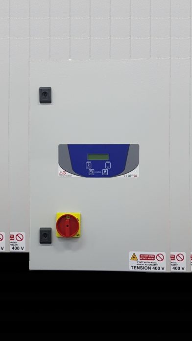
Quadri inverter 3 motori per il controllo della pressione, controllo di livello e sezionatore
generale con bloccaporta.
Inverter control panels 3 motors for pressure control, level control and general
disconnecting switch with door lock.
MADE IN ITALY
INDICE
 INDEX

Istruzioni generali per l'installazione................. General instructions for installing.........................3

Avvertenze....................................................... Warnings.............................................................4

Caratteristiche generali.................................... General characteristics........................................5

Caratteristiche elettriche e meccaniche............ Electrical and mechanical characteristics.............6

Schema di collegamento SQ724.xx.................. Wiring diagram SQ724.xx....................................7

Impiego............................................................ Application...........................................................8

Menu e pulsanti................................................ Menu and buttons................................................8

Programmazione............................................. Programming.......................................................9

Funzionamento generale del quadro................ General functioning of the control panel..............11

Messagi d’allarme............................................ Alarm messages................................................13

Ricerca guasti e soluzioni proposte.................. Troubleshooting and proposed solutions............15

Dichiarazione di conformità.............................. Declaration of conformity...................................16

                                                                     2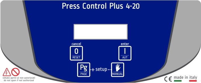
1. ISTRUZIONI GENERALI PER L’INSTALLAZIONE
1. GENERAL INSTRUCTIONS FOR INSTALLING

Assicurarsi che la linea sia protetta, secondo le         Make sure power supply is protected up to
normative, in funzione dell'applicazione.                 standard depending on application. The power
Accertarsi che la potenza e la corrente di targa          of the motor has to be within the control panel's
del motore rispecchino i limiti di impiego del            limits of use.
quadro.                                                   Install the control panel in an environment
Installare il quadro in ambienti adatti al suo            appropriate to its IP54 degree of protection.
grado di protezione IP54. Per il fissaggio                In order to fix the box, use the appropriate holes
dell'involucro, utilizzare gli appositi fori già          which are present or suggested on the bottom.
presenti o predisposti sul fondo. Nell'effettuare         Pay particular attention to not touching or
il fissaggio dell'involucro fare molta attenzione         damaging any components while fixing the box.
a non toccare o danneggiare i vari componenti.            Eliminate whatever metal and/or plastic
Eliminare qualsiasi tipo di impurità metallica e/o        impurity which could happen to fall inside the
plastica che dovesse casualmente cadere                   box (screws, washers, dust…).
all'interno dell'involucro (viti, rondelle,               When connecting electric cables, follow the
polvere…). Effettuare i collegamenti elettrici            wiring diagrams.
rispettando gli schemi di collegamento.                   When fixing the cables in the terminal board
Nel fissare i cavi sulle morsettiere, adoperare           use tools of correct size to avoid damaging the
attrezzi di giuste misure e dimensioni evitando           metal feed clamps and their sockets.
di danneggiare i morsetti metallici e le relative         Before acting upon anything inside, disconnect
sedi. Prima di qualsiasi operazione da                    power supply. Regulation procedures must be
effettuare all'interno, escludere l'alimentazione         carried out by qualified personnel. In case
generale.                                                 protections intervene verify the cause of the
Le operazioni di regolazione all'interno del              problem before resetting.
quadro devono essere svolte da personale                  If necessary substitute the various components
qualificato. In caso di intervento delle protezioni       only with those having the same characteristics
verificarne la causa prima del ripristino.                and components as the originals.
In caso di necessità sostituire i vari componenti
solo con altri aventi le stesse caratteristiche e         It is the installer' s duty to verify the device
portate di quelli originali.                              after the installation although it has already
                                                          undergone regular testing by the
È compito dell'installatore verificare                    manufacturer.
l'apparecchiatura dopo l'installazione
nonostante questa sia già stata sottoposta                The manufacturer is released from all
regolarmente a prove dal costruttore.                     responsibilities for accidents to things or
                                                          people, which derive from misuse of the
Il costruttore declina ogni responsabilità                devices by unauthorized personnel or from
per sinistri a cose o persone dovuti a                    lack of maintenance and repair.
manomissioni delle apparecchiature da
parte di personale non autorizzato o da
carenze nella manutenzione e riparazione.

                                                      3
2. AVVERTENZE
2. WARNINGS

          SCOSSE ELETTRICHE                                           ELECTRIC SHOCKS
          Rischio di scosse elettriche se non osservate quanto        Risk of electric shocks if not complied with the
          prescritto.                                                 requirements.

          PERICOLO                                                    DANGER
          Rischio di danni alle persone, e alle cose se non           Risk of personal injury and property if not complied
          osservate quanto prescritto.                                with the requirements.

          AVVERTENZA                                                  WARNING
          Prima di installare e utilizzare il prodotto leggere        Before installing and using the product read this book
          attentamente il presente manuale in tutte le sue parti.     in all its parts. Installation and maintenance must be
          L'installazione e la manutenzione devono essere             performed by qualified personnel in accordance with
          eseguite da personale qualificato nel rispetto delle        current regulations.
          norme vigenti.                                              The manufacturer will not be held responsible for any
          Il costruttore non risponde di danni provocati da un uso    damage caused by improper or prohibited use of this
          improprio o proibito del quadro e declina ogni              control panel and is not responsible for any damages
          responsabilità per danni provocati da una non corretta      caused by an incorrect installation or maintenance of
          installazione e manutenzione dell’impianto. L'uso di        the plant. The use of non-original spare parts,
          ricambi non originali, manomissioni o usi impropri          tempering or improper use, make the product warranty
          fanno decadere la garanzia.                                 null.

          AVVERTENZA                                                  WARNING
          Accertarsi che la potenza di targa del motore sia           Be sure that the power of the motor is within the control
          all'interno dei limiti di impiego del quadro.               panel range.
          Installare il quadro in ambienti idonei al suo grado di     Install the control panel in an environment appropriate
          protezione IP55.                                            to its IP55 degree of protection.
          Per l'intervento all'interno del quadro usare attrezzi      To operate inside the control panel use tools of correct
          adeguati per evitare danni alle morsettiere.                size to avoid damaging the sockets.

          PERICOLO                                                    DANGER
          Prima di ogni intervento accertarsi che il quadro sia       Before any intervention ensure that the control panel is
          scollegato dall'alimentazione elettrica.                    disconnected from the electricity supply.
          Non effettuare manovre con il quadro aperto.                Do not attempt operations when the control panel is
          Il quadro deve essere collegato ad un efficiente            open.
          impianto di terra.                                          The control panel must be connected to an efficient
          Per il fissaggio del quadro usare gli appositi fori, non    earthing system.
          danneggiare i componenti interni ed eliminare               In order to fix the box use the appropriate holes present
          eventuali detriti di lavorazione all'interno del quadro.    on the bottom, don't damage internal components and
          In caso di intervento delle protezioni eliminare la causa   eliminate any working debris inside the box.
          del malfunzionamento prima di effettuare il ripristino.     In the case of protections eliminate the cause of the
                                                                      malfunction before the restoration.

                                                           4
3. CARATTERISTICHE GENERALI
3. GENERAL CHARACTERISTICS
- Tensione di funzionamento 400Vac ±10% - Operating voltage 400Vac ±10% 50/60Hz
50/60Hz (SQ724.xx) (SQ724.xx)
- Sezionatore generale con blocca porta - General disconnecting switch with door lock
- Pulsante per il funzionamento automatico - Button for automatic operation
- Pulsante per il funzionamento manuale - Button for manual operation
- Alternanza dei 3 motori - Alternance of the 3 motors
- Display a cristalli liquidi per la visualizzazione di: - LCD to visualize:
Frequenzimetro per ogni motore Frequency meter for each motor
Amperometro per ogni motore Ammeter for each motor
Contaore per ogni motore Hour counter for each motor
Pressione impianto Operating pressure
Tutti i messaggi relativi al funzionamento dei 3 All information concerning the operation of the 3
motori motors
- Funzionamento PID - PID functioning
- Fusibile di protezione circuito ausiliario - Auxiliary circuit protection fuse
- Fusibile di protezione per ogni inverter - Protection fuse for each motor
- N°3 inverter - N°3 inverter
- Ventilazione forzata completa di filtri - Forced ventilation complete with filters
- Contenitore esterno in metallo IP54 - External metal box IP54
- Temperatura d'impiego -5/+40°C - Operating temperature -5/+40°C
Ingressi/Uscite Inputs/Outputs
- Ingresso 0-10V - Input 0-10V
- N°2 ingressi in bassissima tensione per - N°2 very low voltage input for float switches or
galleggianti o sonde di livello level probes
Regolazioni Adjustments
- “LINGUA” italiano, inglese, francese e spagnolo - “LANGUAGE” italian, english, french and spanish
- “PRESSIONE START” 0,3÷22,7bar - “START PRESSURE” 0,3÷22,7bar
- “PRESSIONE COSTANTE” 0,6÷23bar - “CONSTANT PRESSURE” 0,6÷23bar
- “PRESSIONE MINIMA” OFF/0,1÷7,5bar - “MINIMUM PRESSURE” OFF/0,1÷7,5bar
- “TRASDUTTORE” 10/16/25bar - “TRANSDUCER” 10/16/25bar
- “CORRENTE MOTORE” 0,5÷45A per ogni motore - “MOTOR CURRENT” 0,5÷45A for each motor
- “FREQUENZA STOP” 35÷45Hz - “STOP FREQUENCY” 35÷45Hz
- “RITARDO STOP” 5÷60sec - “STOP DELAY” 5÷60sec
- “ATTESA PRESENZA RETE” OFF/1÷30min - “SUPPLY MAINS WAITING” OFF/1÷30min
Protezioni Protections
- Marcia a secco con controllo della pressione e del - Dry running with pressure and level control
livello - Loss of pressure control
- Controllo perdita di pressione - Amperometric for each motor
- Amperometrica per ogni motore - Thermal for each motor
- Termica per ogni motore - Overload for each motor
- Sovraccarico per ogni motore - Overload for each inverter
- Sovraccarico per ogni inverter - Overheating for each inverter
- Surriscaldamento per ogni inverter - Inverter minimum voltage
- Tensione minima inverter - Inverter maximum voltage
- Tensione massima inverter
54. CARATTERISTICHE ELETTRICHE E MECCANICHE
4. ELECTRICAL AND MECHANICAL CHARACTERISTICS
THREE-PHASE
CODE POWER OPERATING DIMENSIONS WEIGHT
KW HP CURRENT A B C Kg
SQ724.00 0,75 1 3 x (2,5) 600 400 200
SQ724.01 1,5 2 3 x (4) 600 400 200
SQ724.02 2,2 3 3 x (6) 600 400 200
SQ724.03 4 5,5 3 x (9) 600 400 200
SQ724.04 5,5 7,5 3 x (12) 700 500 250
SQ724.05 7,5 10 3 x (16) 1000 800 300 66
SQ724.06 11 25 3 x (24) 1000 800 300
SQ724.07 15 20 3 x (30) 1000 800 300 68
SQ724.08 18,5 25 3 x (39) 1000 800 300
SQ724.09 22 30 3 x (45) 1000 800 300
65. SCHEMA DI COLLEGAMENTO SQ724.xx
5. WIRING DIAGRAM SQ724.xx
X-1
X-2
X-3
X-4
X-5
X-6
W1
W2
W3
U1
U2
U3
V1
V2
V3
L1
L2
L3
M M M
LINEA DI ALIMENTAZIONE
400Vac 50-60Hz
3 3 3
POWER SUPPLY MOTORE 1 MOTORE 2 MOTORE 3
400Vac 50-60Hz MOTOR 1 MOTOR 2 MOTOR 3
LEGENDA/ KEY
X-1 Sonda comune / common probe
X-2 Sonda minimo / minimum probe
X-3 Sonda massimo / maximum probe
X-4 Trasduttore di pressione V+ / Pressure transducer V+
X-5 Trasduttore di pressione V- / Pressure transducer V-
X-6 Trasduttore di pressione Vout / Pressure transducer Vout
COLLEGAMENTO TRASDUTTORE DI PRESSIONE COLLEGAMENTO CON GALLEGGIANTE
PRESSURE TRANSDUCER WIRING WIRING WITH FLOAT SWITCH
X-1
X-2
X-3
OUT WHITE
- GREEN
+ BROWN
Max 25 mm²
Max 10 mm² Max 6 mm²
(M6)
10 mm 3,2Nm 10 mm 1,4Nm 10 mm 0,5Nm
76. IMPIEGO
6. APPLICATION
L'inverter 3 motori è particolarmente indicato The 3 motors inverter is particularly suitable for
per impianti di pressurizzazione a pressione constant pressure installations with 3electrical
costante con 3 elettropompe. Il quadro non pumps. The device does not need pressure
necessita di pressostati in quanto la centralina switches as the motherboard detects the
rileva la pressione per mezzo di un trasduttore pressure through a pressure transducer
installato sulla tubatura e di conseguenza installed on the pipe and consequently
gestisce le tre pompe. manages the three pumps.
7. MENU E PULSANTI
7. MENU AND BUTTONS
Il quadro dispone di 2 tipi di menu, SETUP e The control panel has 2 types of menu, SETUP
FUNZIONAMENTO. il primo è utilizzato per la and OPERATION. The first one is used only for
programmazione, il secondo per gestire e far programming, the second one to manage and
funzionare il motore. I pulsanti, in funzione al operate the pump. The buttons, according to
tipo di menu, eseguono funzioni differenti. the type of menu, perform different functions.
PULSANTI MENU SETUP MENU FUNZIONAMENTO
BUTTON SETUP MENU OPERATING MENU
Premuto per 1s permette di uscire dal parametro senza salvare Premuto imposta in stato di STOP il motore
Pressing it for 1s allows to exit the parameter without saving Pressing it the motor is set to STOP
Premuto più di 2 s permette di uscire dal setup salvando i dati Premuto ripristina qualsiasi tipo di allarme
Pressing it for more than 2 s exits the setup saving the data Pressing it any alarm is restored
Premuto permette di entrare nel parametro e successivamente Premuto imposta in stato di AUTOMATICO il
confermare il valore impostato motore
Pressing it allows to enter the parameter and then to confirm the set Pressing it the motor is set to AUTOMATIC
value
Serve a scorrere avanti le pagine nel setup
It serves to scroll up the pages on the setup Serve a scorrere le pagine
Serve ad aumentare il valore di un parametro It serves to scroll the pages
It serves to increase the value of a parameter
Serve a scorrere indietro le pagine nel setup Premendolo nello stato di STOP avvia il motore
It serves to scroll down the pages on the setup in modo MANUALE fino al suo rilascio
Serve a ridurre il valore di un parametro Pressing it in STOP modality the motor starts in
It serves to decrease the value of a parameter MANUAL mode until it is released
88. PROGRAMMAZIONE
8. PROGRAMMING
Accendere il quadro ed entro il tempo di Turn the control panel on and within the
ATTESA RETE (10s) entrare nel setup SUPPLY MAINS WAITING time (10s) enter the
premendo contemporaneamente per 2s i tasti + setup by pressing both the + and - buttons for
e -. 2s.
Di seguito l’elenco di tutti i parametri presenti Below is a list of all the parameters in the setup.
nel setup.
SCHERMATA DESCRIZIONE RANGE DEFAULT
SCREEN DESCRIPTION
Permette di selezionare la lingua desiderata ITALIANO
ENGLISH
ITALIANO
FRANCAIS
It serves to set the desired language ESPANOL
Indica il valore di pressione necessario per avviare la pompa
##.# - 24 Bar 2.5 Bar
It indicates the pressure value you need to start the pump.
Indica il valore di pressione che deve essere mantenuto nell'impianto
##.# - 24 Bar 3.0 Bar
It indicates the pressure value you need to maintain in the system.
Indica il valore di pressione sotto il quale la pompa si arresta. Per
ripristinare il blocco bisogna premere il tasto RESET. OFF
- OFF
Indicates the value below which the pump stops. To restore the block it is ##.# bar
necessary to press the RESET button.
Indica il valore del trasduttore utilizzato
10/16/25 Bar 10 Bar
It indicates the value of the transducer used.
È utilizzato per regolare la corrente del motore 1
##.# A ##.# A
It serves to set the motor 1 rated current
È utilizzato per regolare la corrente del motore 2
##.# A ##.# A
It serves to set the motor 2 rated current
È utilizzato per regolare la corrente del motore 3
##.# A ##.# A
It serves to set the motor 3 rated current
È utilizzato per regolare la frequenza di stop delle pompe
35.0 - 45.0 Hz 37.0 HZ
It serves to set the stop frequency of the pumps
9SCHERMATA DESCRIZIONE RANGE DEFAULT
SCREEN DESCRIPTION
È utilizzato per regolare il ritardo di stop della pompa dopo che la
frequenza scende sotto la soglia di stop
5 - 60 s 15 s
It serves to set delay shutdown of the pump after the frequency falls
below the stop threshold.
Permette di ritardare l'avvio del motore una volta acceso il dispositivo.
OFF
- OFF
1 - 30 min
It is used to delay the motor starting when the device is activated
109. FUNZIONAMENTO GENERALE DEL QUADRO
9. GENERAL FUNCTIONING OF THE CONTROL PANEL
All'accensione del dispositivo il display si When you turn on the device, the display lights
illumina e riporta la seguente schermata: up and shows the following screen.
Superato il tempo di ATTESA RETE sul Passed the SUPPLY MAINS WAITING time
display apparirà il menu di funzionamento the display will visualize the functioning menu
dentro il quale è possibile muoversi attraverso il into which it is possible to move through the PG
pulsante PG. Di seguito la sequenza delle sei button.
schermate così come viene visualizzata. La Below is the sequence of the six screens as it
prima schermata visualizza la frequenza del appears.
motore 1, motore 2, motore 3 e la pressione The first screen shows the motor 1, 2, 3
dell'impianto. frequency and the operating pressure.
FREQUENZA MOT. 1 FREQUENZA MOT. 2
FREQUENCY MOT. 1 FREQUENCY MOT. 2
FREQUENZA MOT. 3 PRESSURE
FREQUENCY MOT. 3 PRESSIONE
La seconda indica la corrente di assorbimento, The second screen shows the current
le ore di funzionamento del motore 1 e lo stato absorbed, the operation hours of the motor 1
nel quale si trova: AUTOMATICO, STOP, and the status of the same: AUTOMATIC,
MANUALE. STOP, MANUAL.
La terza indica la corrente di assorbimento, le The third screen shows the current absorbed,
ore di funzionamento del motore 2 e lo stato nel the operation hours of the motor 2 and the
quale si trova: AUTOMATICO, STOP, status of the same: AUTOMATIC, STOP,
MANUALE. MANUAL.
La quarta indica la corrente di assorbimento, The fourth screen shows the current absorbed,
le ore di funzionamento del motore 3 e lo stato the operation hours of the motor 3 and the
nel quale si trova: AUTOMATICO, STOP, status of the same: AUTOMATIC, STOP,
MANUALE. MANUAL.
La quinta indica la temperatura interna del The fifht screen indicates the internal
quadro. Quando la temperatura supera i 30° C temperature of the control panel. When the
la centralina attiva il sistema di ventilazione. temperature exceeds the 30°C the central unit
activates the aeration system.
11La sesta schermata indica lo stato delle sonde, The sixth screen indicates the status of the
dei galleggianti o qualsiasi comande esterno probes, float switch or any external command
che può essere: which can be:
ON: ingresso comando esterno chiuso ON: external command input closed
OFF: ingresso comando esterno aperto OFF: external command input open
1210. MESSAGGI DI ALLARME
10. ALARM MESSAGES
DESCRIZIONE SCHERMATA
DESCRIPTION SCREEN
Se la pressione dell'impianto scende sotto la PRESSIONE MINIMA definita dall'operatore si
produce il seguente allarme e il motore si arresta
In the condition in which the system pressure drops below the MINIMUM PRESSURE value set by
the operator, you will have the following alarm and the consequent block of the pump.
Quando la corrente di uscita è superiore alla corrente nominale, l'inverter taglia l'uscita del motore.
Codice di allarme: OCT
The inverter turns off its output when the output current of the inverter flows greater than the inverter
rated current.
Alarm code: OCT
L'inverter si arresta se la tensione CC del circuito principale supera i 400 V (classe 2S / T) e 820V
(classe 4T) quando il motore decelera. Questo difetto può anche verificarsi a causa di una
sovratensione prodotta dal sistema di alimentazione
Codice di allarme: OVT
The inverter turns off its output if the DC voltage of the DC BUS exceeds 400V for 2S/T class and
820V for 4T class when the motor decelerates. This fault can also occur due to a surge voltage
generated at the power supply system.
Alarm code: OVT
Perdita di fase all'ingresso.
Codice di allarme: COL
Input phase Loss.
Alarm code: COL
Guasto messa a terra
Codice di allarme: GFT
Ground Trip.
Alarm code: GFT
Surriscaldamento dell'inverter
Codice di allarme: OHT
Inverter 1 heatsink overheat.
Alarm code: OHT
La protezione termica interna dell'inverter determina il surriscaldamento del motore. Se il motore è
sovraccarico, l'inverter taglia l'uscita. l'inverter non può proteggere il motore quando si aziona un
motore con più di 4 poli o nel caso di più motori.
Codice di allarme: ETH
The internal electronic thermal of the inverter determines the overheating of the motor. If the motor
is overloaded the inverter turns off the output. The inverter cannot protect the motor when driving a
motor having more than 4 poles or multi motors.
Alarm code: ETH
13DESCRIZIONE SCHERMATA
DESCRIPTION SCREEN
La scala di aumento coppia è troppo grande.
Codice di allarme: OLT
Torque boost scale is set too large.
Alarm code: OLT
La ventola all'interno dell'inverter è difettosa.
Codice di allarme: FAN
The inverter fan is damaged
Alarm code: FAN
Perdita di fase di uscita
Codice di allarme: POE
Output phase Loss.
Alarm code: POE
La protezione IOLT (intervento di sovraccarico dell'inverter) viene attivata al 150% della corrente
nominale dell'inverter per 1 minuto o più.
Codice di allarme: IOLT
IOLT(inverter Overload Trip) protection is activated at 150% of the inverter rated current for 1
minute and greater
Alarm code: IOLT
Si attiva durante un intervento a bassa tensione: la tensione di collegamento DC è inferiore a 180
Vdc per la classe 2S / T e 360 V cc per la classe 4T.
Codice di allarme: LVT
Activated when low voltage trip occurs due to DC link voltage under 180Vdc for 2S/T class and
360Vdc for 4T class.
Alarm code: LVT
Per resettare qualsiasi tipo di allarme To restore any alarm you have to press the
premere il tasto RESET. RESET button.
1411. RICERCA GUASTI E SOLUZIONI PROPOSTE
11. TROUBLESHOOTING AND PROPOSED SOLUTIONS
PROBLEMI COMUNI POSSIBILI CAUSE SOLUZIONI
FREQUENT PROBLEMS CAUSES OPERATION
Alimentare il quadro rispettando
Alimentazione di rete Off la tensione di ingresso
Feed the plant respecting
No supply
the input voltage
Il display non si accende Manopola del sezionatore su 0 Posizionare la manopola del sezionatore su 1
Switch set on 0 Set the switch on 1
Display off
Cavetto flat all’interno del quadro scollegato Collegare correttamente il cavetto flat
dalla scheda madre al display
The cable inside the control panel Connect the cable from the motherboard
is not connected to the display
Allarme pressione minima Mancanza di acqua nel condotto idrico Verificare la presenza di acqua e lo stato
o possibile guasto sulla tubazione della tubazione
Alarm minimum pressure Lack of water in the pipe water or Check the presence of the water
possible failure on the pipeline and the condition of the pipeline
Nel caso in cui uno di questi errori si If one of these errors occurs again please
ripresentasse anche dopo il ripristino 16 require assistance.
richiedere assistenza tecnica.
1512. DICHIARAZIONE DI CONFORMITÁ
12. DECLARATION OF CONFORMITY
Il costruttore: The manufacturer:
Salupo S.a.s. Salupo S.a.s.
Via Laganeto, 129 Via Laganeto, 129
98070 Rocca di Capri Leone (ME) 98070 Rocca di Capri Leone (ME)
Dichiara che: Declares that:
gli avviatori diretti Inverter 3 Plus the Inverter 3 Plus control panels
sono conformi ai requisiti di protezione in comply with the specific protection
materia di sicurezza (bassa tensione) e di prerequisites concerning both safety (low
compatibilità elettromagnetica specifici previsti voltage) and the electromagnetic compatibility
dalle Direttive della Comunità Europea provided for by the European Community laws
2006/95/CEE del 16 Gennaio 2007, 2006/95/CEE of 16th January 2007,
2004/108/CE del 10 Novembre 2007, 2004/108/CE of 10th November 2007,
93/68/CEE del 22 Luglio 1993. Conformità 93/68/CEE of 22th July 1993. Compliance
CEI EN60439-1, EN 61000-6-3, EN 61000-6-1 CEI EN60439-1, EN 61000-6-3, EN 61000-6-1
DIN VDE 0113/EN60204-1 / IEC 204-1. DIN VDE 0113/EN60204-1 / IEC 204-1.
SALUPO S.A.S. SALUPO S.A.S.
Responsabile Ufficio Tecnico Technical Dep. Manager
P.I. Salupo Ivan P.I. Salupo Ivan
1617
18
19
SALUPO
          Via Laganeto, 129
98070 Rocca di Caprileone (ME) ITALY
     Tel.:+39 - (0) 941 - 950216
     Fax:+39 - (0) 941 - 958777
      www.salupoquadri.com
 e-mail: salupo@salupoquadri.com

          UNI EN ISO 9001:2008
Puoi anche leggere