Air Cooled TrueMold Mold Circulator Model MC75-AC
←
→
Trascrizione del contenuto della pagina
Se il tuo browser non visualizza correttamente la pagina, ti preghiamo di leggere il contenuto della pagina quaggiù
Air Cooled TrueMold Mold Circulator
          Model MC75-AC
                                          Item #122211 / Item #122207

                                   INSTRUCTION MANUAL

January 2010                                                     Telephone: (440) 543-1615
IMS Company                                                              Fax: (440) 543-1069
10373 Stafford Road                                          Email: sales@imscompany.com
Chagrin Falls, OH 44023-5296                                 Website: www.imscompany.com

© Copyright 2010 IMS Company. All rights reserved.                   An ISO 9001:2008 Registered Quality Company
                                                       1
TRUE MOLD CONTROL, WITH A NARROW BAND
DESCRIPTION OF ITS OPERATION

1 THE TRUE MOLD CONTROL is designed as a source of high temperature water for
  controlling the temperature of molding equipment. This system has a stainless steel
  water reservoir, which is controlled by a narrow band controller that holds the water
  reservoir to a close temperature tolerance.

      i) There is an electric heater installed in the water reservoir tank, which provides
         the heating. The cooling is done by an air-cooled condenser and ambient air is
         the cooling source for controlling the water temperature. The fan motor that
         distributes air over the condenser is also controlled by a thermocouple sensing
         the return water temperature. The temperature of the water is controlled by a
         thermocouple wire from the controller.

      ii) The main components of the mold control are: stainless steel water reservoir;
          water pump; heater element; fan motor; fan blade; cooling condenser; Narrow
          Brand Solid State Controller.

2 Control System: All functions of unit are controlled by a solid-state narrow band
  controller*. The water pump motor can be started with a switch on the controller. When
  the water pump is running the temperature of the discharge water will displayed on the
  controller. The return water has its own temperature display. When the return water is
  20 F above the set point the cooler supply water will open allow chilled water to flow
  through the chilled water heat exchanger. This will cool the water to the mold to the
  proper temperature.

      i) The unit has a high temperature cut-out. If the water temperature goes over
         2500 F, the controller will cut out the heating element.

      ii) There is a low water float installed in the reservoir. If the water reaches a low
          level, the float will cut the system out till the reservoir is filled to proper
          level.

*There is a rotary OFF, ON & REMOTE switch, which controls the
Electrical power to the unit. The REMOTE option is in place should this
option be added at a later time.

                                            5

                                                                                 MC75 - AC
INSTALLATION
1. Inspect carton that the unit has been shipped in for damage. Report any damage to
the carrier. NOTE: Take exception on any unit received when the carton shows any
damage. That will help protect you from concealed damage. After inspection remove
the carton.
2. Some suggestions on selecting location.
Where the unit has easy excess for continuous observation.
The heat is discharged out the top of the unit by the fan. Do not install with a
low ceiling over the unit. Must have 12’ of clearance.
The air being discharged is very hot – perhaps up to 250°F. Would cause harm
to a person if allowing the air to flow over them.
The discharge and return water lines are also very hot. Take caution and post
a warning notice to all employees.
Maintenance should be considered when installing give easy excess to all
controls.
Keep unit as close as possible to mold being controlled. And also keep hoses
to mold as short as possible to prevent heat loss.
3. You must fill the water reservoir with clean water. Please do not use any water
that will cause contamination, like tower water. Your new mold controller is designed
to be contaminate free. You will affect the heat transfer by using dirty water that
will affect good heat transfer. Fill reservoir to level as marked on the water sight
glass. The reservoir fill line is on the back of this unit. The unit also has both an
overflow fitting in the event you over fill the system, and a reservoir drain valve.
Periodically you should flush out the system.
4. Installation of unit:
Connect mold supply line to mold control. Unit is marked, DISCHARGE &
RETURN. Keep these supply lines full size to unit being temperature
controlled. The discharge line is the inlet of hot water to the mold. Return is the
water being returned to the mold control.
The electrical power to the unit must be same as marked on data plate.
Keep wiring to match any electrical code you must meet. Under sizing the
supply lines will harm the unit.
With the power and rotary switch7on, you then must turn the 24 volt manual
switch on this will allow the display readout on the controller to light up. You must
set the temperature you want to keep the mold. To do this you must push in the
button on the mold controller as marked and turn knob to temperature you desire
MC75 - ACthe mold to be kept at with this temperature setting.
Check for proper rotation of the water pump and fan. There is a rocket arm switch on
the mold controller to start water pump and check rotation.
After checking rotation, setting the temperature of water you need for the mold,
you can now start the water pump. The unit is ready for operation.
The mold controller will start the operation. When water pump is running the
5. electrical heater will come on, and the heater light will be on. When set temperature
is reached then the heater light the heating element will go off. If the return water
should go over 2o F above the set point then the fan will come on, and the cooling
light will be on at this time. When the temperature reaches the set temperature, the
fan will cycle off. Please note fan rotation. It should be clockwise from the top
of unit. When mold controller is set properly the unit will maintain the set
temperature automatically. The narrow band controller automatically selects heating
or cooling.
6. Please do not use oil in this reservoir. You might want to add an inhibit, ethylene
glycol. But only if necessary.
7. CAUTION: This unit has a circuit protection installed in the electrical enclosure. All
three powers are protected with fuses. Make sure to use the correct size fuses.
Make sure the electrical power is off before you work on the unit. The power
supply connection is in the control panel marked L1, L2 & L3, and there is a marked
grounding lug. Do not by-pass this.
8. Live Electrical Contacts could cause death or shock. NOTE: Please make sure
the power is off before you work on the electrical power circuit. Use a meter to
check for power off. This could be a dangerous process if precautions are not
taken. Only qualified electricians are to do electrical work. The wiring to this
machine must be proper sized as per the electrical code. You must ground this unit.
No short cuts on electrical wiring.
9. Don't forget the water in this system is very hot to the touch, it will cause harm to
anyone who touches this piping. Be sure you wear protection when working with
this mold controller.
10. When installing the power cord to this unit, first make sure it is the correct size. The
cord must be 600 VOLT TESTED, with four #12 wires with one being the ground.
YOU MUST always use the ground.
11. You MUST ALWAYS close the electrical enclosure before you turn the power on.
Don't forget to check rotation of water8pump. Make sure the voltage you apply to
this mold controller matches the data plate on unit.
MC75 - ACMAINTENANCE - PART I
1. Maintenance to mold controller:
; Flush out water reservoir as needed. Do not allow this unit to run with dirty
supply water.
; Blow out condenser as needed. Do not allow this condenser to become
clogged. You will cause poor heat transfer on the cooling cycle.
; You can remove the condenser coil cover, same as service panel.
; All motors have internal overload protection. There are no lubrication joints to
any motor.
; All motors have internal overload protection. There are no lubrication joints to
any motor.
2. When replacing the heating element. MAKE SURE the electrical power supply is
turn. Check power with meter.
; Drain water tank.
; Remove the electrical leads to the element. Power must be off. You should
apply some type of lubricant (WD40) to remove these screws.
; Remove the four 5/16 - 18 stainless steel cap screw. NOTE: You must lubricate
(WD40) while removing. Do not force the nuts off.
; Remove element (7.5 KW)
; Clean the tank surface plate, to make sure you have a clean surface for the
gasket.
; If replacing the heater make sure it is stainless steel on the back up plate.
; Always use a new gasket.
; Install gasket on element and put electrical element in place.
14
MC75 - ACSerie Infrared Universale / Universal Infrared Series
Manuale d’uso
User manual
Technology & EvolutionIndice Contents
1. Introduzione 1 1. Introduction to the IR Series 1
1.1 Caratteristiche principali 1 1.1 Main features 1
1.2 Descrizione del frontale degli strumenti 2 1.2 Front panel 2
2. Utilizzo degli strumenti della serie Infrared Universale 3 2. Use of Universal Infrared Instruments 3
3. Installazione 4 3. How to install the controller 4
4. Configurazione di fabbrica 5 4. Easy set-up: factory-set configuration 5
5. Modi di funzionamento. 6 5. Advanced set-up: different modes of operation 6
6. Programmazione 11 6. Programming the IR controller 11
6.1 Accesso da tastiera 11 6.1 Access via keypad 11
6.2 Modifica del set-point (St1) 11 6.2 Set-point modification (St1) 11
6.3 Modifica del secondo set-point (St2) 11 6.3 Second set-point modification (St2) 11
6.4 Modifica dei parametri di tipo “P” 11 6.4 Modification of 'P' parameters 11
6.5 Modifica dei parametri di tipo “C” 12 6.5 Modification of 'C' parameters 12
6.6 Parametri “C” per termocoppie, sonde in tensione 6.6 'C' parameters for thermocouples, current and
e in corrente 12 voltage sensors 12
6.7 Come modificare il Modo (parametro C0) 13 6.7 How to modify the mode of operation (parameter C0) 13
6.8 Accesso da telecomando 13 6.8 Programming the controller via remote control 13
6.9 Modifica parametri da telecomando 15 6.9 How to modify parameters via remote control 15
6.10 Stato della regolazione durante la modifica dei parametri 16 6.10 Performance of the controller during programming
6.11 Validità della modifica parametri 16 procedures 16
6.12 Reset del controllo 16 6.11 Confirming the newly set values 16
6.13 Sistemi avanzati di programmazione e supervisione 16 6.12 Reset of the control 16
7. Descrizione dei parametri 17 6.13 Advanced programming tools and Supervisory systems 16
– St1 Set-point principale 17 7. Description of the parameters 17
– St2 Set-point secondario 17 – St1, main set-point 17
– C0 Modo di funzionamento 18 – St2, second set-point 17
– P1 Differenziale di St1 18 – C0 Mode of operating 18
– P2 Differenziale di St2 19 – P1, differential of St1 18
– P3 Differenziale Zona Neutra 19 – P2, differential of St2 19
– C4 Autorità 19 – P3, dead zone 19
– C5 P o P+I 20 – C4, authority 19
– C6 Ritardo degli inserimenti di uscite differenti 21 – C5, P or P+I 20
– C7 Tempo minimo tra due accensioni successive 21 – C6, time-delay before energizations of different outputs 21
– C8 Tempo minimo di spegnimento 22 – C7, minimum time-interval between succ. energizations 21
– C9 Tempo minimo di attivazione 22 – C8, minimum disenergization time-interval 22
– C10 Ritardo delle uscite in caso di allarme sonda (Er0) 23 – C9, minimum energization time-interval 22
– C11 Rotazioni 23 – C10, time-delay before sensor alarm (Er0) 23
– C12 Tempo di ciclo PWM 25 – C11, rotations 23
– C13 Tipo di sonda 26 – C12, PWM cycle time 25
– P14 Calibrazione 26 – C13, type of sensor 26
– C15 Valore minimo per ingressi in corrente e tensione 27 – P14, calibration 26
– C16 Valore massimo per ingressi in corrente e tensione 27 – C15, min. value of voltage and current inputs 27
– C17 Filtro sonda 28 – C16, max. value of voltage and current inputs 27
– C18 Unità di misura per temperatura: “C” o “F” 28 – C17, sensor response 28
– C19 Seconda sonda NTC 29 – C18, temperature unit of measure °C/°F 28
– Funzionamento differenziale C19=1 29 – C19, second NTC sensor 29
– Compensazione C19=2, 3 o 4 31 – C19=1, differential 29
_ C21 Valore minimo ammesso da ST1 34 – C19=2,3,4, offse 31
– C22 Valore massimo ammesso da St1 34 – C21, lower St1 threshold 34
_ C23 Valore minimo ammesso da ST2 34 – C22, higher St1 threshold 34
– C24 Valore massimo ammesso da St2 35 – C23, lower St2 threshold 34
– P25 SET Allarme di “Bassa” 35 – C24, higher St2 threshold 35
– P26 SET Allarme di ALTA 35 – P25, low temperature set-point 35
_ P27 Differenziale ALLARME: reset 36 – P26, high temperature set-point 35
_ P28 Ritardo attivazione allarme 38 – P27, alarm differential: reset 36
_ C29 Gestione ingresso digitale 1 38 – P28, time-delay before alarm activation 38
_ C29=3 allarme esterno ritardato (ritardo=P28) – C29, digital input no. 1 38
con Resert Manuale 39 _ C29=3 Delayed external alarm with manual resert (P28) 39
_ C29=4 ON/OFF 39 _ C29=4 ON/OFF 39
_ C30 Gestione ingresso digitale 2 40 – C30, digital input no. 2 40
_ C31 Stato uscite con allarme da ingresso Digitale 40 – C31, output status in the event of alarm via digital input 40
_ C32 Indirizzo seriale 41 – C32, serial address 41
_ C33 Funzionamento “speciale” 41 – C33, special mode of operation 41
– C50 Abilitazione tastiera e/o telecomando 42 – C50, operating keypad and/or remote control 42
– C51 Telecomando: codice abilitazione 42 – C51, remote control: access code 42
8. Descrizione funzionamento speciale 43 8. Special mode of operation 43
8.1 Descrizione DIPENDENZA: C34, C38, C42, C46 43 8.1 DEPENDENCE: C34, C38, C42, C46 438.2 Funzionamento TIMER 44 8.2 TIMER 44
8.3 Descrizione TIPO DI USCITA: C35, C39, C43, C47 44 8.3 TYPE OF OUTPUT: C35, C39, C43, C47 44
8.4 Descrizione INSERZIONE: C36, C40, C44, C48 44 8.4 ENERGIZATION: C36, C40, C44, C48 44
8.5 Descrizione DIFFERENZIALE/LOGICA: C37, C41, 8.5 DIFFERENTIAL/LOGIC: C37, C41, C45, C49 46
C45, C49 46 8.6 Further information on the special mode of operation 47
8.6 Note integrative al funzionamento speciale 47 8.7 Hints for choosing the right mode 50
8.7 Suggerimenti per scegliere il Modo di partenza 50 8.8 Some examples about the special mode of operation 51
8.8 Esempi di utilizzo del Funzionamento speciale 51
9. Lista completa dei parametri 58 9. Advanced set-up: list of the parameters 58
10. Ricerca e eliminazione dei guasti (strumento e 10. Troubleshooting - Reset of controller and remote
telecomando) 60 control 60
11. Condizioni di allarme, cause e rimedi 61 11. Alarm conditions, causes and remedies 61
12. Moduli opzionali 62 12. Optional modules 62
12.1 Modulo uscita analogica 62 12.1 Analogue output module - code CONV0/10A0 62
12.2 Modulo ON/OFF 64 12.2 ON/OFF module (code CONV0N0FF0) 64
12.3 Modulo alimentatore/convertitore 66 12.3 Power supply/Converter module (code CONV0/1L00) 66
13. Caratteristiche tecniche dei modelli serie 13. Technical specifications of Universal Infrared
Infrared universale 68 instruments 68
13.1 Caratteristiche tecniche del telecomando 69 13.1 Technical specifications of the remote control 69
14. Schemi di collegamento 70 14. Wiring diagrams 70
14.1 Versioni IR32 NTC 70 14.1 IR32 with NTC input 70
14.2 Versioni IR32 non NTC 71 14.2 IR32 with Pt100, J/K tc or V/I input 71
14.3 Versioni IRDR NTC e non NTC 73 14.3 IRDR Versions 73
14.5 Connessione sonde 74 14.4 Sensor connection diagrams 74
Glossario 75 Glossary 75
Tabella codici dei modelli serie Infrared universale 76 Codes of the Universal Infrared models 76
Dimensioni 78 Dimensions 781. Introduzione 1. Introduction to the IR Series
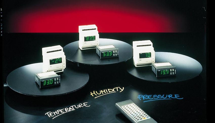
Gli strumenti della serie Infrared Universale sono stati pro- The controllers of the Universal Infrared Series have been
gettati per il controllo delle principali grandezze fisiche specifically designed to control pressure, humidity and
(temperatura, pressione, umidità) in unità di condiziona- temperature in air-conditioning, refrigeration and heating
mento, refrigerazione e riscaldamento. units.
1.1 Caratteristiche principali 1.1 Main features
Gamma: per soddisfare ogni esigenza di controllo sono a Range: there are 41 models with different outputs and dif-
disposizione 41 modelli con diverse uscite e differenti ali- ferent power supply so as to satisfy any requirement (see
mentazioni (vedi tabella codici riportata a pagina 76). table on, page 76). Three optional modules designed to
Inoltre sono disponibili tre moduli opzionali per le versioni D further upgrade the instruments' functions are available for
e A in grado di ampliare ulteriormente l’utilizzo degli strumenti. versions A and D.
Flessibilità: sono disponibili modelli con alimentazione Flexibility: power supply can be 12/24Vac-dc,
12/24 Vac-dc, 110/240 Vac-dc e 24/240 Vac. Possono esse- 110/240Vac-dc and 24/240Vac. The IR range can be
re montati a pannello o su guida DIN. panel or DIN Rail mounted.
Collegamento seriale: tutti i controlli sono predisposti Serial Connection: all IR instruments can be network
al collegamento in rete per la realizzazione di sistemi connected to supervisory and telemaintenance systems.
di supervisione e teleassistenza.
Accessori: a richiesta, è disponibile il telecomando Optional units: remote control, useful to program and
per la programmazione e il comando a distanza dei control parameters from a distant point; optional modules.
controlli e, inoltre, dei moduli opzionali.
Omologazioni: la qualità e sicurezza dei controlli Infrared Approvals: the quality and safety of the Infrared control-
Universali sono garantite dal sistema di progettazione e lers is guaranteed by the ISO 9001 design and production
produzione certificato ISO 9001, nonché dal marchio CE. system. Furthermore they have been certified by the CE
mark.
Applicazioni: sono molteplici. I controlli sono programmati Applications: being extremely versatile, the IR instru-
per il funzionamento “Reverse”, ma possono essere ments offer plenty of applications. They are programmed
facilmente programmati dall’utente per il funzionamento to work in the “Reverse” mode but they can be programmed
“Direct” o personalizzato. by user to work also in the “Direct” (or customizer) mode
Nota: per il significato di Reverse e Direct si rimanda al Note: for the Reverse and Direct meaning see Glossary
glossario. at the end of this manual).
11.2 Descrizione del frontale degli strumenti 1.2 Front panel
3 4 5 6
3 4 5 7
6 8 7
reverse direct
SEL 8
reverse direct
PRG
mute IR32 PRG
mute
SEL
IRDR
2 1 2 1 Fig.1
1 – Display: visualizza il valore della sonda collegata. 1 – Display: shows the value measured by the connected
In caso di allarme il valore della sonda viene visualizzato sensor. In the event of alarm condition the sensor value
alternativamente ai codici degli allarmi attivi. Durante la will be displayed alternately with the codes of the active
programmazione mostra i codici dei parametri ed il loro alarms. When programming the instrument, the display
valore. shows the parameter codes being introduced and their
values.
2 – LED decimale: viene acceso quando la grandezza 2 – Decimal Point LED: lights up when the controlled
controllata è visualizzata con la risoluzione del decimo. parameter is displayed.
3 – LED Reverse: lampeggia quando almeno un relè con 3 – Reverse LED: flashes when at least one relay
funzionamento “Reverse” è attivo. Il numero di lampeggi working in the “Reverse” mode is active. The Led flashes
indica i relè attivi in Reverse. Tra una fase di lampeggio as many times as the number of active 'reverse' relays.
e la successiva il LED rimane spento per 2 secondi. There is a two seconds' pause between a flashing stage
and the next one.
4 – LED Direct: lampeggia quando è attivo almeno un 4 – Direct LED: flashes when at least one relay working
relè in funzionamento “Direct”. Valgono le altre considera- in the “Direct” mode is active. Its working logic is the same
zioni viste per la funzione “Reverse”. as the “Reverse” LED.
5 – Tasto SEL: visualizza e/o imposta il set point. Se pre- 5 – SEL Button: displays and/or allows you to select the
muto insieme al tasto PRG/MUTE per 5 secondi permette Set-point. If pressed for 5 seconds together with
di inserire la password e di accedere ai parametri di confi- PRG/MUTE it allows you to enter the password and the
gurazione (parametri con codice tipo “Cxx”). configuration parameters (having a “Cxx” type code).
6 – Tasto PRG/Mute: premuto per 5 secondi dà accesso 6 – PRG/Mute Button: if pressed for 5 seconds it allows
al menù dei parametri di utilizzo più frequente (codice tipo you to access the menu of the more frequently used para-
“Pxx”). In caso di allarme tacita il buzzer. Resetta le altre meters (having a “Pxx” type code). In the event of alarm
segnalazioni d’allarme se premuto al cessare della causa. condition, it silences the buzzer and, if pressed after the
Termina la programmazione fissando in memoria i valori cause that determined the alarm has disappeared, it
dei parametri modificati. resets any other alarm. It completes the programming pro-
cedure storing all the values of the modified parameters.
7 – Tasto : incrementa il valore del set-point o di ogni 7 – Button : increases the value of the set-point or
altro parametro selezionato. that of any other selected parameter.
8 – Tasto : decrementa il valore del set-point o di ogni 8 – Button : decreases the value of the set-point or
altro parametro selezionato. Nelle versioni con ingresso that of any other selected parameter. In NTC input ver-
NTC, se premuto quando sul display è visualizzato il valo- sions it can display the value of the second sensor (hol-
re della sonda, permette la visualizzazione della seconda ding “Down” pressed while the display shows the value of
sonda per il tempo in cui il tasto resta premuto. the main sensor).
Nota: per i codici dei modelli della serie Infrared Note: for Infrared Universal, Series models, please refer
Universale, fare riferimento alla tabella alla fine del to the table at the end of the manual
manuale.
22. Utilizzo degli strumenti della serie 2. Use of Universal Infrared Instruments
Infrared Universale
Gli strumenti della serie Infrared Universale sono estrema- The Infrared instruments are extremely versatile, flexible
mente flessibili e permettono di ottenere prestazioni eleva- controllers providing excellent performance. There are
te. Esistono tre tipologie di parametri di programmazione three types of programming parameters:
del controllo: 1. "set-point";
1. “set-point”; 2. type "P" parameters, that is frequently used parameters;
2. parametri di tipo “P”, o parametri di uso frequente; 3. type "C" parameters, useful to get a customized
3. parametri di tipo “C” per la configurazione configuration of the instrument.
personalizzata del controllo.
A seconda dell’utilizzo, si possono infatti presentare le Consequently the IR can be used as follows:
seguenti situazioni:
1) lo strumento viene utilizzato con l’impostazione 1) with the factory-set configuration (see chapter 4).
prevista in fabbrica (vedi cap. 4). It is enough to check and, if necessary, modify set-point
In tal caso sarà sufficiente verificare ed eventualmente and P parameters.
modificare il set-point e i parametri P. Note: in current/voltage input models or thermocouples J,
Nota: nei modelli con ingresso in corrente, tensione o per it may be necessary to modify some C parameters (see
termocoppia J potrà essere necessario modificare anche description of parameters C13, C15, C16 and C19).
alcuni parametri di configurazione. Si veda la descrizione
dei parametri C13, C15, C16 e C19.
2) Lo strumento è destinato ad utilizzi diversi da quelli 2) the instrument is intended for uses requiring a dif-
previsti in fabbrica (vedi cap. 5). ferent configuration (see chapter 5).
In questo caso la prima operazione da fare è scegliere il First of all choose the suitable mode of operation of the
Modo di funzionamento adatto all’utilizzo.Ciò è possibile IR by simply modifying the C0 configuration parameter.
modificando un solo parametro di configurazione: il parametro C0. C0 can be given 9 different values corresponding to 9 dif-
Il parametro C0 può assumere 9 diversi valori, ad ognuno ferent operating modes. Then, if necessary, modify set-
corrisponde un particolare Modo di funzionamento. point and P parameters according to your application
Scelto il Modo di funzionamento adeguato alla propria requirements.
applicazione si potrà poi eventualmente modificare il Set
point e i parametri P.
3) Nel caso di applicazioni particolari, può essere 3) Special configurations may require the modification
necessario modificare anche gli altri parametri di configu- of some other configuration parameters. For example, you
razione. Si può, ad esempio, programmare il funziona- can program the operating mode of the digital inputs
mento degli ingressi digitali (parametri C29, C30) e defini- (parameters C29 and C30) and set output energization
re le tempistiche di attivazione delle uscite (parametri C6, times (param. C6, C7, C8, C9). Models with NTC input
C7, C8, C9). Nei modelli con ingresso NTC è possibile uti- can be connected to a second sensor so as to control the
lizzare una seconda sonda per il funzionamento “differen- instrument in a "differential" or "compensating" mode. The
ziale” o in “compensazione”. È addirittura possibile perso- Mode of Operation itself can be customized (see C33,
nalizzare il Modo di funzionamento (si veda il parametro page 41) thus creating new modes by modifying one of
C33 a pag. 41) creando nuovi “Modi” adattando o modifi- the 9 modes allowable by the parametera C0.
cando uno dei 9 modi previsti dal parametro C0.
33. Installazione 3. How to install the controller
Per l’installazione del controllo procedere come indicato di To install the controller follows these indications and
seguito, tenedo presente gli schemi di collegamento riportati respect the connection diagram as indicated at the end of
alla fine del manuale. this manual.
1) collegare sonde ed alimentazione: le sonde possono 1) Connect sensors and power supply: sensors can be
essere remotate fino ad una distanza massima di 100 metri located up to 100 meters distant from the controller provi-
dal controllo purché si usino cavi con sezione minima di 1 ded that you use cables with 1mm2 min. dia., better if
mm2, possibilmente schermati. Per migliorare l’immunità ai shielded. To improve immunity against noises we recom-
disturbi si consiglia di usare sonde con cavo schermato (col- mend using sensors with shielded cables (connect just
legare un solo estremo dello schermo alla terra del quadro one end of the shielding to the earth of the electrical
elettrico). Nel caso si utilizzino termocoppie è obbligatorio panel). When using thermocouples it is compulsory to use
usare cavo compensato con schermo per avere una corretta compensated shielded cables to ensure protection against
immunità ai disturbi; le termocoppie possono essere prolun- noises. Thermocouples can be used with an extension
gate solo usando oltre ai cavi compensati anche eventuali lead provided that you use compensated cables and con-
connettori compensati (per i codici vedi listino Carel). nectors (for models and codes see Carel price list).
2) Programmare lo strumento: per una descrizione più 2) Program the instrument: see chapter "Programming
approfondita vedere il capitolo “Programmazione” a pag. 11. the instrument" on page 11.
3) Collegare gli attuatori: è preferibile collegare gli attua- 3) Connect all devices: connect the other devices after
tori solo dopo aver programmato il controllo. Al riguardo si you have programmed the controller. Please check relays
raccomanda di valutare attentamente le portate massime power as indicated in the "Technical characteristic" table
dei relè indicate nelle “caratteristiche tecniche” (pag. 68). on page 68.
4) Collegamento in rete seriale: se è previsto l’allacciamento 4) Link up the IR to serial network: if the IR controller is to
alla rete di supervisione tramite le apposite schede seriali be linked up to a supervisory network through the dedicated
(IR32SER per i modelli IR32 e IRDRSER per i modelli IRDR) è serial boards (IR32SER for IR32 models and IRDRSER for
necessario curare la messa a terra del sistema. In particolare IRDR models), it is necessary to pay attention to the earthing
non dovrà essere collegato a terra il secondario dei trasformato- of the system. In particular the secondary of the transformers
ri che alimentano gli strumenti. Nel caso sia necessario colle- which feed the instruments MUST NOT be earthed. Should
garsi ad un trasformatore con secondario a terra, dovrà you need to connect the IR to a transformer whose secon-
essere interposto un trasformatore di isolamento. È possibi- dary is earthed, it is necessary to add an isolating transfor-
le collegare più strumenti allo stesso trasformatore di isola- mer. It is possible to connect several instruments to the same
mento, tuttavia è consigliabile utilizzare un trasformatore isolating transformer but we suggest using as many isolating
di isolamento per ogni strumento. transformers as the number of instruments.
Avvertenze: Important:
Evitare comunque l’installazione dei controlli in ambienti Avoid installation in places with the following features:
con le seguenti caratteristiche: – relative humidity higher than 90% or condensing;
– umidità relativa maggiore dell’90% o condensante; – heavy vibrations or shocks;
– forti vibrazioni o urti; – exposure to continuous jets of water;
– esposizioni a continui getti d’acqua; – exposure to aggressive and polluting environments
– esposizione ad atmosfere aggressive ed inquinanti (e.g.: sulphurous and ammoniacal gases, saline mist,
(es: gas solforici e ammoniacali, nebbie saline, fumi) smoke) to avoid corrosion and/or oxidation;
per evitare corrosione e/o ossidazione; – high magnetic and/or radio interferences (avoid
– alte interferenze magnetiche e/o radiofrequenze installation near transmitter aerials);
(evitare quindi l’installazione delle macchine vicino ad – exposure of controllers to direct solar radiation and to
antenne trasmittenti); atmospheric agents in general.
– esposizioni dei controlli all’irraggiamento solare diretto
e agli agenti atmosferici in genere.
Nel collegamento dei regolatori: When connecting the regulators follow these instructions:
– utilizzare capicorda adatti per i morsetti in uso; – use appropriate cable-terminals
– allentare ciascuna vite ed inserirvi i capicorda, quindi (suitable to the terminals used);
serrare le viti. Ad operazione ultimata tirare leggermente – slacken each screw and insert the wire terminals, then
i cavi per verificarne il corretto serraggio; tighten the screws again and check by slightly pulling
– separare quanto più possibile i cavi delle sonde e degli the cables;
ingressi digitali dai cavi dei carichi induttivi e di potenza – keep separate the cables of the sensors and digital
per evitare possibili disturbi elettromagnetici; inputs from the inductive and power cables, to avoid
– non inserire mai nelle stesse canaline (comprese quelle any electromagnetic interference;
dei quadri elettrici) cavi di potenza e cavi sonde; – never put power cables and sensor cables in the same
– evitare inoltre che i cavi delle sonde siano installati nelle channel;
immediate vicinanze di dispositivi di potenza (contattori, – avoid installing sensor cables near power devices
interruttori magnetotermici, ecc.); (magnetothermic switches or others);
– evitare di alimentare il controllo direttamente con – do not power the controller to the general power source
l’alimentazione generale del quadro qualora l’alimentatore of the electrical panel when it has to power several
debba alimentare diversi dispositivi, quali contattori, devices (electrovalves, contactors, etc.).
elettrovalvole, ecc.: i quali necessiteranno di un altro
trasformatore. Important: the uncorrect connection to the power source
Attenzione: il non corretto allacciamento della tensione could damage the system.
di alimentazione può danneggiare seriamente il sistema. It is necessary to add to the unit the electromechanical
Predisporre sull’unità tutti i dispositivi elettromeccanici di devices to guarantee the safety of the system.
sicurezza utili per garantire la sicurezza dell’impianto.
44. Configurazione di fabbrica 4. Easy set-up: factory-set configuration
I regolatori della serie Infrared vengono forniti già pro- The IR controller is supplied ready for use in the
grammati con impostato il funzionamento Reverse (vedi "Reverse" operation mode. The applications available are
glossario), che permette il loro utilizzo in diverse applicazioni, numerous and vary according to the type of sensor con-
a seconda della sonda collegata. I regolatori possono essere nected to the instrument:
collegati a:
sonde di temperatura (NTC, Pt100, termocoppie): con- models with temperature sensors (NTC, Pt100,
trollo di forni, bruciatori, impianti di riscaldamento in genere; Thermocouples): control of ovens, burners, heating
systems;
sonde di umidità: controllo di umidificatori e umidificazione models with humidity sensors: control of humidifiers
in genere; and humidification processes;
sonde di pressione: controllo evaporatori e in genere di models with pressure sensors: control of evaporators
contrasto alle basse pressioni. and in general low pressure alarms.
I valori di fabbrica del set e degli altri parametri sono: Factory-set values:
It is always possible, however, to modify the factory-set
configuration so as to make your instrument fulfil your
specific application requirements.
Parametro Codice Valore di fabbrica Campo
Parameter Code Factory-set value Range
Set-point St1 20.0 limite sonda
Set-point sensor limit
Differenziale P1 2.0 0.1/99.9
Differential
Calibrazione sonda P14 0.0 -99/+99
Sensor calibration
Allarme di bassa P25 limite inferiore sonda -99 / P26
Lower limit alarm sensor lower limit
Allarme di alta P26 limite superiore sonda P25/999
Higher limit alarm sensor higher limit
Differenziale allarme P27 2.0 0.1/99.9
Alarm Differential
Ritardo allarme P28 60 minuti
Alarm Delay 60 minutes 0/120 min.
55. I Modi di funzionamento 5. Modes of operation
Prima di analizzare in dettaglio i singoli parametri è necessario Before examining each single parameter, here is a
descrivere i nove Modi di funzionamento previsti, ai quali description of each of the nine modes of operation that
si accede tramite il parametro C0. L’impostazione dello can be set through C0. Such a function is highly innovati-
strumento mediante i modi di funzionamento rappresenta ve for instruments in this price bracket. Setting the suitable
infatti una funzionalità innovativa in strumenti di questo mode of operation is the most important operation you
livello di prezzo. Inoltre la scelta del Modo di funzionamento should do when the factory-set configuration does not suit
corretto è la prima azione da compiere nel caso in cui la con- your needs.
figurazione di fabbrica, ovvero il funzionamento reverse,
non sia adatto alla propria applicazione.
Modo 1: funzionamento Direct CO=1 Mode 1: DIRECT control action, C0=1
Parametri fondamentali: Main parameters:
– set-point (St1); – set-point (St1);
– differenziale (P1). – differential (P1).
Nel funzionamento Direct il regolatore opera un’azione di In the Direct operation mode the controller reduces the
contenimento qualora la grandezza regolata sia superiore value of the controlled parameter when it goes beyond the
al valore di set-point. Fissato il punto di lavoro desiderato set-point range. Once the set-point has been set (St1) the
(St1), le uscite sono attivate una alla volta man mano che outputs will be energized one by one as the parameter
la grandezza supera St1. I relè presenti nei modelli con più increase St1. The relays in the models with more outputs
uscite sono distribuiti equamente all’interno dell’unico diffe- are equally distributed within the selected differential.
renziale impostato. Quando la grandezza controllata è When the controlled value is equal to/higher than St1+P1
uguale o superiore a St1+P1 tutte le uscite sono attive. all outputs will energize. Vice-versa, when the controlled
Viceversa, se la grandezza, partendo da valori superiori a value starts to decrease, any energized relay will be disenergi-
St1, inizia a diminuire, eventuali relè attivi vengono spenti zed as the value approaches St1. When the St1 value is
man mano che ci si avvicina a St1. Al valore St1 tutte le reached, all outputs will disenergize. The Direct LED will
uscite sono spente. Il LED Direct lampeggia solo se ci sono flash only in the event of energized outputs; the number of
uscite attive ed il numero di impulsi è pari ai relè inseriti. flashings will correspond to the number of relays.
mod. V mod. W mod. Z
OUT 1 OUT 1 OUT 2 OUT 1 OUT 2 OUT 3 OUT 4
D D D D D D D
Diff.(P1) Diff.(P1) Diff.(P1)
Set (St 1) Set (St 1) Set (St 1)
Fig.2
Modo 2: funzionamento Reverse CO=2 Mode 2: REVERSE mode C0=2
È il Modo predefinito in fabbrica. I parametri fondamentali This is the factory-set mode. The main parameters are
di questo tipo di funzionamento sono il set point (St1) e il set-point (St1) and differential (P1).
differenziale (P1).
mod. V mod. W mod. Z
OUT 1 OUT 2 OUT 1 OUT 4 OUT 3 OUT 2 OUT 1
R R R R R R R
Diff.(P1) Diff.(P1) Diff.(P1)
Set (St 1)
Set (St 1) Set (St 1)
Fig.3
Fissato il punto di lavoro desiderato (St1), le uscite vengono The outputs will be energized one by one as the control-
attivate una alla volta man mano che la grandezza led parameter decreases from the previously selected set-
diminuisce a valori inferiori di St1. Nei modelli a più uscite point (St1). In models with more outputs the energization
l’attivazione dei relè è equamente distribuita all’interno del of the relays will occur within the differential (see fig. 3).
differenziale (vedi figura 3).
When the controlled variable is less or equal to St1-P1, all
Quando la grandezza controllata è inferiore o uguale a the outputs are energized. When the controlled variable
St1-P1 tutte le uscite sono attive. Se la grandezza, parten- below the set-point begins to increase its value, the ener-
do da valori inferiori a St1, inizia ad aumentare, eventuali gized relays will gradually disenergize as the value
relè attivi vengono spenti man mano che ci si avvicina a approaches St1. When the variable reaches the set-point
St1. Al valore St1 tutte le uscite sono spente. value, all outputs will disenergize. The Reverse LED will
Il LED Reverse lampeggia con un numero di impulsi pari flash; the number of flashings will correspond to the num-
alle uscite attive. ber of energized outputs.
6Modo 3: funzionamento ZONA NEUTRA CO=3 Mode 3: Dead-Zone mode C0=3
Parametri fondamentali: Main parameters:
– set-point (St1); – set-point (St1);
– differenziale dell’azione Reverse (P1); – differential of the reverse mode (P1);
– differenziale dell’azione Direct (P2); – differential of the direct mode (P2);
– ZONA NEUTRA (P3). – Dead-zone (P3).
Lo scopo del regolatore è di portare la grandezza misurata The controller aims at bringing the controlled variable
all’interno di un intervallo a cavallo del set-point (St1), within a limited range, called dead zone, set around the
detto zona morta. L’estensione della zona morta dipende dal Set-point (St1). As shown in the graph below, the dead
valore del parametro P3. All’interno della zona morta lo zone value depends on the value given to P3. No devices
strumento non richiede l’intervento di alcun dispositivo. will be actuated within the dead zone. Beyond the dead
Al di fuori della zona morta lo strumento lavora in Modo zone the controller works in the Direct Mode when the
Direct quando la grandezza controllata aumenta e in controlled variable increases and in the Reverse Mode
Modo Reverse quando diminuisce. A seconda del modello when it decreases its value. Depending on the model,
usato, possono esserci uno o più relè nei funzionamenti there can be one or more relays. The outputs will energize
Direct e Reverse. Tali uscite sono attivate o spente una or disenergize as described above in mode 1 and 2,
alla volta secondo le modalità già viste nei modi 1 e 2, in depending on the value of the controlled variable, of St1,
conformità ai valori assunti dalla grandezza controllata, P1 and P2. The Direct and Reverse LEDs will flash as
dal valore St1, da P1 e da P2. Il LED Direct e il LED described on page 1.
Reverse lampeggiano con le modalità già viste nel
paragrafo “descrizione del frontale degli strumenti” a pag.1.
Attenzione: quando lo strumento è fornito di un’unica uscita Important: when the instrument has only one relay out-
a relè, essa funziona in Modo Reverse con ZONA NEUTRA. put, it will work in the Reverse mode with dead zone.
mod. V mod. W
OUT 1 OUT 1 OUT 2
R R D
Diff.(P1) (P3) Diff.(P1) (P3) (P3) Diff.(P2)
Neutral zone
Neutral zone
Set (St 1) Set (St 1)
mod. Z
OUT 2 OUT 1 OUT 3 OUT 4
R R D D
Diff.(P1) (P3) (P3) Diff.(P2)
Set (St 1)
Neutral zone
Set (St 1) Fig.4
Modo 4: funzionamento PWM CO=4 Mode 4: PWM mode, C0=4
Parametri fondamentali: Main parameters:
– set-point (St1); – set-point (St1);
– differenziale dell’azione Reverse (P1); – differential of the reverse mode (P1);
– differenziale dell’azione Direct (P2); – differential of the direct mode (P2);
– ZONA NEUTRA (P3). – DEAD ZONE (P3).
La logica di regolazione del Modo 4 è la stessa già vista The operation logic is the same as in Mode 3. The instru-
per il Modo 3. È un funzionamento con ZONA NEUTRA con ment, in fact, bases its action on the dead zone; the relays
la sola particolarità che i relè vengono attivati in modo impulsi- energize according to the PWM (Pulse Width Modulation)
vo in base alla procedura PWM (Pulse Width Modulation, procedure. In practice, each single relay energizes in a
modulazione della larghezza d’impulso). Ogni singolo relè period of 20 seconds (this time-delay can be modified
è attivato in un periodo di 20 secondi (periodo eventualmente through C12, see page 14) from a time (calculated in per-
modificabile tramite il parametro C12, vedi pagina 14) per un centage). The relay energization is proportional to the
tempo variabile calcolato in percentuale; il tempo di ON del relè position of the controlled variable within the differential.
è proporzionale alla posizione occupata dalla grandezza For slight deviations from the set value, the output will
controllata all’interno del differenziale. Per scostamenti conte- energize for a short time. When the value exceeds the dif-
nuti, l’uscita si attiverà per un tempo breve. Al superamento del ferential, the relay will remain energized (100% ON). The
differenziale, il relè sarà sempre inserito (100% ON). Il funziona- PWM mode allows your instrument to energize devices
mento PWM permette quindi di inserire in modo “proporziona- whose mode is typically ON/OFF in a proportional way
le” attuatori con funzionamento tipicamente ON/OFF (es. resi- (e.g. heaters). The PWM mode can be used to get a
stenze di riscaldamento) per migliorare il controllo della gran- modulating signal 0/10V or 4/20mA (IR models equipped
dezza regolata. Il funzionamento PWM può essere impiegato with outputs for Solid State Relay (A, D) and dedicated
anche per ottenere un segnale modulante di comando di tipo optional converter, see chapter 12.1). When in the PWM
0/10 V o 4/20 mA utilizzando la versione IR con uscite per mode, the Direct/Reverse LEDs will flash; the number of
il comando di relè a stato solido (A, D), disponendo della flashings will correspond to the number of energized out-
relativa opzione per convertire il segnale (capitolo 12.1). puts. If the controller has only one relay, it will work in the
Nel funzionamento PWM i LED Direct/Reverse lampeggiano Reverse mode with DEAD ZONE.
7con un numero di impulsi pari al numero di uscite (impulsive) Important: do not use the PWM mode with compressors
attive. Quando lo strumento è fornito di un solo relè, essa funzio- or devices requiring frequent On/Off routines. Do not give
na in modo Reverse con ZONA NEUTRA. C12 a minimum value because this might compromise the
Attenzione: è assolutamente sconsigliato l’utilizzo PWM relays life (about 1 million pulses).
con compressori o altri attuatori la cui affidabilità può
risentire di inserimenti/spegnimenti troppo ravvicinati.
In ogni caso si consiglia di non ridurre a valori minimi il
parametro C12, per non compromettere la durata dei relè
(calcolata in circa 1 milione di attivazioni).
mod. V mod. W
OUT 1 OUT 1 OUT 2
R R D
Diff.(P1) (P3) Diff.(P1) (P3) (P3) Diff.(P2)
Neutral zone
Neutral zone
Set (St 1) Set (St 1)
mod. Z
OUT 2 OUT 1 OUT 3 OUT 4
R R D D
Diff.(P1) (P3) (P3) Diff.(P2)
Neutral zone
Set (St 1) Fig.5
Modo 5: funzionamento “ALLARME” CO=5 Mode 5: Alarm mode C0=5
Parametri fondamentali: Main parameters:
– set-point (St1); – set-point (St1);
– differenziale dell’azione Reverse (P1); – differential of the reverse mode (P1);
– differenziale dell’azione Direct (P2); – differential of the direct mode (P2);
– ZONA NEUTRA (P3); – DEAD ZONE (P3);
– set dell’allarme di “Bassa” (P25); – set of the lower limit alarm (P25);
– set dell’allarme di “Alta” (P26); – set of the higher limit alarm (P26);
– differenziale dell’allarme (P27); – alarm differential (P27);
– tempo di ritardo dell’attuazione dell’allarme (P28). – alarm time delays (P28).
Con il Modo 5 uno o più relè vengono attivati per segnalare la In this mode one or more relays energize as soon as
presenza di un allarme generico (sonda scollegata o in corto, there is a generic alarm condition (disconnected or short-
funzionamento anomalo dell’elettronica) o un allarme di “Alta” circuited sensor, faulty electronics, etc.) or a specific High
o “Bassa”. Nelle versioni V e W è previsto un unico relè d’allar- or Low alarm condition. In versions V and W there is only
me, nella versione Z due: viene attivato il relè 3 per gli allarmi one alarm relay, version Z has two: relay no. 3 for generic
generici e per l’allarme di “Bassa”, mentre il relè 4 viene attivato and low alarm conditions, relay no. 4 for generic and high
per gli allarmi generici e per l’allarme di “Alta”. L’attivazione del alarms. In addition to the energization of the relay, the
relè di allarme si somma alle usuali segnalazioni attive con gli controller displays the alarm code and makes the buzzer
altri modi di funzionamento ovvero codice di allarme sul sound (in models equipped with acoustic signal). In
display e segnale acustico (nelle versioni provviste di buz- models W and Z, the relays not used to indicate alarm
zer). Nel caso delle versioni W e Z, i relè non utilizzati per conditions are dedicated to the regulation as described
la segnalazione degli allarmi sono dedicati alla regolazio- above for Mode 3 (see Fig.6).
ne con le modalità viste nel Modo 3, come rappresentato
nei diagrammi sottostanti.
mod. V mod. W
OUT 1 OUT 1 OUT 2
R
Diff.(P27) Diff.(P1) (P3) Diff.(P27)
High/Low Alarm Neutral zone High/Low Alarm
(P25/P26) Set (St 1) (P25/P26)
mod. Z
OUT 3 OUT 1 OUT 2 OUT 4
R D
Diff.(P27) Diff.(P1) (P3) (P3) Diff.(P2) Diff.(P27)
(P25) Low Alarm Neutral zone High Alarm (P26)
Set (St 1) Fig. 6
8Modo 6: commutazione Direct/Reverse da ingresso Mode 6: Direct/Reverse selection from digital input
digitale CO=6
Parametri fondamentali: Main parameter:
– set-point 1 (St1); – set-point 1 (St1);
– differenziale di St1 (P1) dell’azione Direct; – differential of St1 (P1), direct mode;
– set-point 2 (St2); – set-point 2 (St2);
– differenziale di St2 (P2) dell’azione Reverse. – differential of St2 (P2), reverse mode.
Lo strumento commuta dal funzionamento Direct a quello The instrument changes from Direct to Reverse (see
Reverse (vedi Modo 1 e Modo 2) in funzione dello stato Mode 1 and Mode 2) according to the condition of the
dell’ingresso digitale 1. Più precisamente si ha: funzionamento digital input no. 1. More precisely: direct mode (St1) when
Direct riferito a St1 quando l’ingresso digitale è aperto, digital input 1 is open; reverse mode (St2) when digital
funzionamento Reverse riferito a St2 quando è chiuso. input 1 is closed.
mod. V mod. W mod. Z
OUT 1 OUT 1 OUT 2 OUT 1 OUT 2 OUT 3 OUT 4
D D D D D D D
Diff.(P1) Diff.(P1) Diff.(P1)
Set (St 1) Set (St 1) Set (St 1)
INGRESSO DIGITALE APERTO/ DIGITAL INPUT OPEN
mod. V mod. W mod. Z
OUT 1 OUT 2 OUT 1 OUT 4 OUT 3 OUT 2 OUT 1
R R R R R R R
Diff.(P2) Diff.(P2) Diff.(P2)
Set (St 2) Set (St 2) Set (St 2)
INGRESSO DIGITALE CHIUSO/ DIGITAL INPUT CLOSED Fig.7
Modo 7: funzionamento Direct con commutazione di Mode 7: Direct mode with change of Set and differen-
set e differenziale da ingresso digitale CO=7 tial via digital input, C0=7
Parametri fondamentali: Main parameters:
– set (St1); – set-point (St1);
– differenziale di St1 (P1); – differential (P1);
– set (St2); – set-point (St2);
– differenziale di St2 (P2). – differential (P2).
Con questo Modo la variazione di stato dell’ingresso digi- When C0=7 any variation of digital input no. 1 (open/clo-
tale 1 (aperto/chiuso) non cambia il tipo di azione (sempre sed) does not change the mode (that remains always
Direct) ma cambia il set-point ed il differenziale. La regola- Direct) but changes both set-point and differential. The
zione è basata su St1 e il differenziale P1 attivi quando regulation is based on St1 and P1 which operate when
l’ingresso digitale è aperto e su St2 e il differenziale P2 the digital input is open and on St2 and P2 which operate
quando l’ingresso digitale è chiuso. when the digital input is closed.
mod. V mod. W mod. Z
OUT 1 OUT 1 OUT 2 OUT 1 OUT 2 OUT 3 OUT 4
D D D D D D D
Diff.(P1) Diff.(P1) Diff.(P1)
Set (St 1) Set (St 1) Set (St 1)
INGRESSO DIGITALE APERTO/ DIGITAL INPUT OPEN
mod. V mod. W mod. Z
OUT 1 OUT 1 OUT 2 OUT 1 OUT 2 OUT 3 OUT 4
D D D D D D D
Diff.(P2) Diff.(P2) Diff.(P2)
Set (St 2) Set (St 2) Set (St 2)
INGRESSO DIGITALE CHIUSO/ DIGITAL INPUT CLOSED Fig.8
9Modo 8: funzionamento Reverse con commutazione di Mode 8: Reverse mode with set-point and differential
set e differenziale da ingresso digitale CO=8 change via digital input, C0=8
Parametri fondamentali: Main parameters:
– set-point (St1); – set-point (St1);
– differenziale (P1). – differential (P1).
Con questo Modo la variazione di stato dell’ingresso digi- When C0=8 any variation of digital input no.1 (open/clo-
tale 1 (aperto/chiuso) non cambia il tipo di azione (sempre sed) does not change the mode (that remains always
Reverse) ma cambia il set ed il differenziale. Reverse) but changes both set-point and differential.
La regolazione è basata su St1 e il differenziale P1 quando Regualtion in based on St1 and P1 which operate when
l’ingresso digitale è aperto ed St2 e il differenziale P2 the digital input is open; St2 and P2 which operate when
quando l’ingresso digitale è chiuso. the digital input is closed.
mod. V mod. W mod. Z
OUT 1 OUT 2 OUT 1 OUT 4 OUT 3 OUT 2 OUT 1
R R R R R R R
Diff.(P1) Diff.(P1) Diff.(P1)
Set (St 1) Set (St 1) Set (St 1)
INGRESSO DIGITALE APERTO/ DIGITAL INPUT OPEN
OUT 1 OUT 2 OUT 1 OUT 4 OUT 3 OUT 2 OUT 1
R R R R R R R
Diff.(P2) Diff.(P2) Diff.(P2)
Set (St 2) Set (St 2) Set (St 2)
INGRESSO DIGITALE CHIUSO/ DIGITAL INPUT CLOSED Fig.9
Modo 9: funzionamento con 2 set-point, uno in Direct
e uno in Reverse CO=9 Mode 9: 2 set-points, one in Direct and one in
Parametri fondamentali: Reverse, C0=9
– set-point 1 (St1); Main parameters:
– differenziale di St1 (P1) dell’azione Reverse; – set-point 1 (St1);
– set-point 2 (St2); – differential of St1 (P1), reverse mode;
– differenziale di St2 (P2) dell’azione Direct. – set-point 2 (St2);
Questo Modo, operativo solo nelle versioni W e Z è simile – differential of St2 (P2), direct mode.
al Modo 3 (funzionamento con zona neutra), in quanto C0 can be set as 9 only in models W and Z. This mode is
metà uscite sono attive in Direct e metà in Reverse. similar to mode 3 (dead zone control action) as half of the
La sua particolarità è che non esiste alcun vincolo nel outputs energize in Direct and half in Reverse.
posizionamento dei set-point delle due azioni, per cui si In this mode there is no compulsory positioning of the set-
può operare come se si avessero due strumenti indipen- point. Therefore it is as if you had two independent instru-
denti che lavorano con la stessa sonda. ments working with the same sensor.
OUT 1 mod. W OUT 2
R D
Diff.(P1) Diff.(P2)
Set (St 1) Set (St 2)
mod. Z
OUT 2 OUT 1 OUT 3 OUT 4
R R D D
Diff.(P1) Diff.(P2)
Set (St 1) Set (St 2)
Fig.10
106. Programmazione 6. Programming
I parametri di programmazione del controllo, che abbiamo All programming parameters (1.'set-point'; 2. "P" parame-
suddiviso in tre tipologie, (1.“set-point”; 2. parametri di ters, that is frequently used parameters; 3. “C" parameters
tipo “P”, o parametri di uso frequente; 3. parametri di tipo to get customized configurations) can be modified via key-
“C” per la configurazione personalizzata del controllo), pos- pad or remote control.
sono essere modificati mediante tastiera o telecomando.
6.1 Accesso da tastiera 6.1 Access via keypad
Per i set-point l’accesso è diretto premendo il tasto SEL; The set-points can be directly displayed by pressing SEL.
per modificare i parametri “P” è necessario premere il In order to modify "P" parameters hold down PRG for 5
tasto PRG per 5 secondi; tutti i parametri di “TIPO C” sono seconds. All "C" parameters are protected by a password
invece protetti da password: con password = 22 è possibile (when password = 22 you can enter and modify parame-
accedere e modificare i parametri C0 e C13,15,16 oltre a ters C0, C13, 15 and 16 in addition to all "P" parameters;
tutti i parametri di tipo “P”; con password = 77 è possibile if password = 77 you can enter and modify all parame-
accedere e modificare tutti i parametri del controllo. ters).
Vediamo ora in dettaglio le procedure di modifica.
6.2 Modifica del set-point (St1) 6.2 Set-point modification (St1)
Per modificare il set-point (valore previsto in fabbrica To modify the factory-set set-point (St1=20) follow these
St1=20): instructions:
a) premere il tasto “SEL” per qualche secondo: a display a) hold down "SEL" for a few seconds; the display shows
compare St1; St1;
b) rilasciare il tasto “SEL”: a display lampeggia il valore b) release "SEL"; the factory-set value flashes on the
attuale del set-point; display;
c) premere i tasti o per raggiungere il valore c) press or until you reach the desired value;
desiderato; d) press "SEL" to confirm the new St1 value.
d) premere “SEL” per confermare il nuovo valore di St1.
6.3 Modifica del secondo set-point (St2) 6.3 Second set-point modification (St2)
Nei modi di funzionamento 6, 7, 8 e 9 lo strumento lavora In operating modes 6, 7, 8 and 9 the controller requires
con due set-point. Per modificare entrambi i set-point: two set-points. To modify both of them:
a) premere il tasto “SEL” per qualche secondo: a display a) hold down "SEL" for a few seconds; the display shows
compare St1; St1;
b) rilasciare il tasto “SEL”: a display lampeggia il valore b) release "SEL"; the actual value of St1 flashes;
attuale del set-point 1;
c) press or until you reach the desired value;
c) premere i tasti o fino a raggiungere il valore d) press "SEL" to confirm the new St1;
desiderato di St1; e) after having confirmed St1 the display shows for few
d) premere “SEL” per confermare il nuovo valore di St1; seconds St2 then its actual value begins to flash;
e) dopo aver confermato St1 lo strumento visualizza a
display il codice St2 per qualche secondo, dopodiché f) press or until you reach the desired value;
compare lampeggiante il valore attuale di St2; g) press "SEL" to confirm the new St2;
h) the display shows the value measured by the main
f) premere i tasti o fino a raggiungere il valore desiderato; sensor.
g) premere il tasto “SEL” per confermare il dato St2;
h) a display riappare il valore rilevato dalla sonda principale.
6.4 Modifica dei parametri di tipo “P” 6.4 Modification of “P” parameters
Per modificare il differenziale (valore previsto in fabbrica To modify the factory-set differential (P1=2) and "P" para-
P1=2) e gli altri parametri “P”: meters:
a) premere il tasto “PRG” per 5 secondi: a display compare “P1”; a) hold down "PRG" for 5 seconds: the display shows “P1”;
b) premere il tasto o fino a visualizzare il b) press or until you display the parameter you
parametro da modificare; want to modify;
c) premere il tasto “SEL”: a display compare il valore c) press "SEL" ; the actual value of the chosen parameter
attuale del parametro; appears on the display;
d) premere o fino a raggiungere il valore desiderato; d) press or until you reach the desired value;
e) premere “SEL” per confermare il dato; e) press "SEL" to confirm the new value;
f) a display compare il codice per identificare il param. modificato; f) the display shows the code that identifies the modified
g) ripetere le operazioni dal punto b) ad f), se si vogliono parameter;
modificare altri parametri, altrimenti passare al punto h); g) repeat operation from point b) to f), should you need to
h) premere “PRG” per memorizzare i dati modificati e change other values, otherwise go on to point h);
ritornare al funzionamento normale. h) press "PRG" to store all modifications and return to
normal working operation.
11Puoi anche leggere