LB80 - LB100 - Pompe a membrana Diaphragm pumps Istruzioni per l'uso e manutenzione Instructions for the use and maintenance - Varisco.sk
←
→
Trascrizione del contenuto della pagina
Se il tuo browser non visualizza correttamente la pagina, ti preghiamo di leggere il contenuto della pagina quaggiù
LB80 - LB100

            Pompe a membrana
             Diaphragm pumps

     IT   Istruzioni per l’uso e manutenzione                      2
     EN   Instructions for the use and maintenance                 9

                                       Ed. 2014/10 - Rev. 00 - Code 554
INSTRUZIONI PER L’USO E MANUTENZIONE - LB80 - LB100

                                                    ATTENZIONE
    NON METTERE IN FUNZIONE LA POMPA PRIMA DI AVERE LETTO E BEN COMPRESO QUESTO MANUALE.
    LA VARISCO SPA DECLINA OGNI E QUALSIASI RESPONSABILITÀ PER DANNI DOVUTI ALLA NEGLIGENZA ED ALLA
    MANCATA OSSERVANZA DI QUANTO RIPORTATO NEL PRESENTE MANUALE.
    LA VARISCO SPA NON RISPONDE DEGLI EVENTUALI DANNI CAUSATI DA ERRATE INTERPRETAZIONI DELLE
    ISTRUZIONI CONTENUTE NEL PRESENTE MANUALE E PER DANNI CAUSATI DA UNA INSTALLAZIONE
    ERRATA E/O DA UN USO IMPROPRIO DELLA POMPA STESSA.

                                 INDICE
     1   GARANZIA……………………………………………………..……                         2
     2   PRESCRIZIONI GENERALI……………………..…………..……                  3
     3   DESCRIZIONE DELLE POMPE LB80 E LB100……………......          3
     4   NORME DI SICUREZZA E PREVENZIONE INFORTUNI…….            3
     5   MOVIMENTAZIONE E TRASPORTO……..…………………….                  4
     6   STOCCAGGIO…..………..………………………………………..                      4
     7   INSTALLAZIONE……....…………………………………………..                    4
     8   AVVIAMENTO…………..……………………………………….…                        5
     9   USO E IMPIEGO……………………….…………………………..                      5
    10   MANUTENZIONE……………………………………………….….                        6
    11   MALFUNZIONAMENTO: CAUSE E RIMEDI……...…………….              6
    12   SMONTAGGIO E MONTAGGIO.......…………………………….                6
    13   RICAMBI…………….………………………………………………                          8
    14   ROTTAMAZIONE…………………….…………………………….                        8
    15   DICHIARAZIONE DI INCORPORAZIONE………………………                15
    16   ESPLOSI …………………………………………………………..                        16

1         GARANZIA
Tutti i nostri prodotti sono garantiti per un periodo di 12 mesi dalla data della prima messa in servizio e comunque non
oltre 18 mesi dalla data di consegna. Le riparazioni effettuate in garanzia non interrompono la decorrenza del periodo di
garanzia. La garanzia concerne difetti di materiale e di lavorazione che compromettano il funzionamento del prodotto e lo
rendano non idoneo all’uso al quale il prodotto è destinato, purché denunciati tempestivamente e comunque non oltre 2
giorni dalla loro scoperta. Sono esclusi i danneggiamenti derivanti dalle caratteristiche fisico/chimiche del liquido
aspirato, così come i danneggiamenti delle parti che per natura o destinazione sono soggette a usura o a deterioramento
(guarnizioni di tenuta, diaframmi, valvole a vuoto e a pressione, parti di gomma o plastica), o che dipendono dal mancato
rispetto delle istruzioni d’uso e/o manutenzione, dal cattivo o inadeguato utilizzo o immagazzinamento del prodotto o da
modifiche o riparazioni effettuate da personale non espressamente autorizzato dalla VARISCO SpA. La non
identificabilità del numero di matricola è causa di esclusione della garanzia. La nostra prestazione di garanzia è
tassativamente subordinata al fatto che l’acquirente abbia ottemperato a tutte le proprie obbligazioni maturate sino al
giorno della richiesta ed a quelle scadenti nel corso dell’intervento in garanzia. La decisione se emettere una nota di
accredito, riparare o sostituire la merce, è presa ad insindacabile giudizio dalla VARISCO SpA. Il rientro della merce può
essere fatto solo se autorizzato per iscritto, e porto franco VARISCO SpA - Padova. Tutte le spese di
smontaggio/rimontaggio del prodotto dal/sul luogo di installazione ed ogni altro intervento su cantiere restano a carico
dell’acquirente. La merce riparata o sostitutiva sarà riconsegnata all’acquirente franco fabbrica VARISCO SpA - Padova.
La merce sostituita diventa di proprietà della VARISCO SpA. È inteso che la suddetta garanzia è assorbente e sostitutiva
delle garanzie o responsabilità previste per legge, ed esclude ogni altra responsabilità della VARISCO SpA (risarcimento
del danno, mancato guadagno, campagne di ritiro, manodopera dell’acquirente, fermo cantiere, diminuzione del prezzo
di vendita, ecc.).
In caso di controversia è di esclusiva competenza il foro di Padova.

Esclusioni dalla garanzia
La garanzia decade (oltre a quanto riportato nel contratto di fornitura):
- Qualora si dovesse verificare un errore di manovra imputabile all’operatore.
- Qualora il danno fosse imputabile ad insufficiente manutenzione.
- Qualora fossero utilizzati pezzi di ricambio non originali.
- Qualora non fossero state seguite le istruzioni riportate in questo manuale.
Rimangono altresì esclusi dalla garanzia i danni derivanti da negligenza, incuria, cattivo utilizzo e uso improprio della
pompa. La rimozione dei dispositivi di sicurezza, di cui la pompa è dotata, farà decadere automaticamente la garanzia e
le responsabilità della Ditta Costruttrice.

2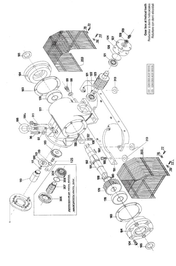
INSTRUZIONI PER L’USO E MANUTENZIONE - LB80 - LB100

2        PRESCRIZIONI GENERALI
All’atto del ricevimento controllare subito lo stato del materiale, in particolare eventuali danni dovuti al trasporto.
Controllare inoltre l’esatta corrispondenza con la bolla di consegna. In caso di contestazione, segnalare subito al vettore
il danno e comunicarlo entro 48 ore alla sede di Padova.
Per ogni comunicazione segnalare sempre il tipo di pompa che è stampigliato sull’apposita targhetta oppure il numero di
matricola.
Le pompe vanno utilizzate esclusivamente per gli impieghi per i quali il Costruttore ha precisato:
- i materiali di costruzione
- le condizioni operative (pressione, numero di giri, temperatura, ecc.)
- i settori di applicazione.
Ogni altro utilizzo a cui la macchina venisse destinata e non contemplato in questo manuale, scarica la Ditta
Costruttrice da ogni e qualsiasi responsabilità per danni a persone, animali o cose.
Per impieghi non precisati dal Costruttore, contattare l’Ufficio Tecnico della VARISCO S.p.A. al seguente numero:
049 82 94 111.

3        DESCRIZIONE DELLE POMPE LB80 E LB100
I materiali di costruzione delle parti metalliche a contatto del liquido possono essere: in lega di alluminio, in lega di
alluminio anticorodal, in ghisa, in acciaio inossidabile AISI304 o AISI316, in lega di alluminio con plastificazione in Rilsan,
o con rivestimento in resina fluororata (Blue Armor).
Le membrane e le valvole possono essere realizzate nei seguenti materiali: neoprene, dutral, hypalon, viton, gomma
nitrilica, gomma atossica, o silicone atossico.

3.1      DESCRIZIONE DELLA POMPA LB80
La LB80 è una pompa a membrana autoadescante con bocche di aspirazione e mandata filettate 3"Gas o flangiate
DN80.
La membrana è azionata da una biella elastica o rigida autolubrificata che non richiede manutenzione fino a 5000 ore di
lavoro.
Il riduttore che collega il motore al sistema biella-manovella può essere costruito in lega leggera di alluminio o in ghisa.
Gli ingranaggi della trasmissione possono essere a dentatura diritta o elicoidale con rapporti di trasmissione 1:43 oppure
1:38 oppure 1:30, per fornire la portata richiesta al variare del numero di giri del motore di azionamento.

3.2      DESCRIZIONE DELLA POMPA LB100
La LB100 è una pompa autoadescante a membrana a doppio corpo con bocche di aspirazione e mandata flangiate
DN100 PN16.
Le due membrane sono azionate da due bielle elastiche autolubrificate che non richiedono manutenzione fino a 5000 ore
di lavoro.
Il riduttore che collega il motore alle manovelle di estremità è costruito in ghisa.
Gli ingranaggi della trasmissione sono a vite senza fine con rapporti di trasmissione 1:43 oppure 1:26 per fornire la
portata richiesta al variare del numero di giri del motore di azionamento.

4        NORME DI SICUREZZA E PREVENZIONI INFORTUNI
Se la pompa è fornita con un motore applicare quanto segue.
Non fare funzionare il motore a scoppio o diesel all'interno di un ambiente chiuso.
I gas di scarico contengono ossido di carbonio, un veleno inodore e mortale.
Non avvicinare mani o piedi alle parti in movimento o rotanti.
Non tenere, versare o utilizzare combustibili in presenza di una fiamma libera, e di dispositivi come stufe,
caldaie o di apparecchi in grado di generare scintille.
Non effettuare rifornimenti di combustibile in ambienti chiusi e scarsamente ventilati.
Non rifornire il serbatoio carburante con il motore in funzione.
Lasciare raffreddare il motore prima di procedere al rifornimento.
Conservare i combustibili in recipienti appositi approvati a norme di sicurezza.
Non togliere il tappo serbatoio carburante mentre il motore è in funzione.
Non fare funzionare il motore se si sente odore di benzina o se esiste qualche altro rischio di esplosione.
Non azionare il motore se si verifica una fuoriuscita di combustibile.
Non trasportare il motore con benzina nel serbatoio.
Non controllare l'accensione con le candele o il cavo della candela staccati: servirsi di un tester apposito.
Non fare girare il motore con la candela smontata.
Non colpire il volano con oggetti contundenti o metallici in quanto ciò può causare la rottura e il distacco di
parti metalliche durante il movimento.
Non toccare silenziatori, cilindri o alette di raffreddamento quando sono caldi, poiché il contatto può essere
causa di ustioni.

                                                                                                                             3
INSTRUZIONI PER L’USO E MANUTENZIONE - LB80 - LB100

5        MOVIMENTAZIONE E TRASPORTO
La massa della macchina è riportata in modo leggibile e indelebile sulla macchina stessa.
La macchina può essere movimentata solo con tubazioni di aspirazione e mandata scollegate e con motore di
alimentazione fermo o disinserito.
Le macchine installate su basamento, o su barella possono essere movimentate con apparecchi di sollevamento
collegabili con opportuni sistemi di sicurezza al gancio di sollevamento previsto sulla macchina stessa.

6        STOCCAGGIO
Se la pompa dovesse essere immagazzinata per un lungo periodo, far defluire il liquido sollevando la valvola di
aspirazione o mandata ed inclinando la pompa nella direzione di quest’ultima.
Se lasciata all’aperto, coprire la macchina con telo impermeabile e lubrificare i cuscinetti della manovella per prevenire la
ruggine.

7        INSTALLAZIONE
Per quanto riguarda l'uso dei motori accoppiati alla pompa si fa riferimento ed espresso richiamo alle norme impartite dai
costruttori dei motori stessi allegate a questo manuale d’uso e manutenzione.
Installare i gruppi elettropompa o motopompa provvisti di basamento metallico su fondazioni stabili e ben ancorate al
terreno.
Assicurarsi che il piede di stazionamento delle versioni su carrello sia bloccato nella posizione di appoggio per mezzo del
perno di fissaggio con inserimento della spina di sicurezza che impedisca l'eventuale fuoriuscita del perno dalla sua
sede.
Le tubazioni di collegamento alla pompa devono essere di tipo flessibile o provviste di tronchetti flessibili di gomma per
smorzare le vibrazioni dovute alla portata a flusso pulsante.
E' buona norma impedire l'entrata di corpi solidi di grandi dimensioni (max dimensione 50 mm), che potrebbero causare
la rottura della membrana o della biella, montando un filtro protettivo in aspirazione, fornibile a richiesta.
La condotta di aspirazione e mandata deve avere un diametro uguale o superiore a quello delle bocche di aspirazione o
mandata della pompa.
Evitare il più possibile curve, gomiti o strozzature che possano limitare l'afflusso o il deflusso del liquido alla o dalla
pompa.
Non montare valvole di fondo: la pompa è provvista di valvole a clapet che fungono da valvole di non ritorno.
Non montare sulla mandata valvole di strozzamento del flusso; per parzializzare la portata prevedere sulla mandata una
tubazione di by-pass con ritorno al bacino di aspirazione regolato da valvola a sfera o a saracinesca.
Assicurarsi che tutti i giunti siano a perfetta tenuta d'aria: controllare i filetti, le guarnizioni delle flange, delle bocche, e i
raccordi rapidi.
Installare la pompa il più vicino possibile al fluido da pompare, cercando ove possibile di diminuire la lunghezza della
tubazione di aspirazione (l’altezza d’aspirazione massima è di 6 metri); così facendo diminuisce il tempo di
innescamento e si può ottenere una maggiore portata.
La prevalenza totale massima della pompa è di 15 metri di colonna d'acqua; maggiori carichi idraulici influiscono
negativamente sul funzionamento della pompa e causerebbero una limitata vita della membrana. Per usi continuativi la
prevalenza manometrica totale non deve superare i 10 metri di colonna d'acqua.
La corretta installazione delle tubazioni di aspirazione e mandata è assicurata dall'osservanza del senso di flusso
richiamato nella maggior parte delle versioni con frecce direzionali sulle bocche di aspirazione e mandata o comunque
verificando che l'aspirazione è sulla bocca che monta tappo o cassa d'aria.
Nell'installazione di gruppi con motore endotermico assicurarsi che l'inclinazione massima del motore non superi i 35° in
senso trasversale o longitudinale per garantire un corretto valore di lubrificazione.

4
INSTRUZIONI PER L’USO E MANUTENZIONE - LB80 - LB100

8          AVVIAMENTO
Le pompe LB sono autoadescanti fino ad una profondità di aspirazione di 6m (consigliamo un limite di 3m per una
maggiore efficacia dell’operazione).
Non è quindi necessario riempire con il liquido il corpo pompa o la tubazione di aspirazione.
Prima dell’avviamento leggere le istruzioni e le norme di sicurezza dei motori accoppiati al gruppo pompa fornito e
attenersi rigorosamente alle disposizioni impartite dal costruttore del motore stesso.
Per quanto riguarda i gruppi pompa LB80 e LB100, prima dell'avviamento:
−      Riempire il carter dell'olio riduttore fino al livello massimo segnalato dall'asta livello olio.
−      Provvedere poi alla chiusura di tappo olio e asta di livello.

Quantità e marca dell'olio da usare secondo la tabella seguente (viscosità ISO 150):

                                             LB80
    Versione alluminio pressofuso: 0,65 litri            Versione elicoidale: 0,75 litri

                                            LB100
                                            0,75 litri

                    MARCA                                            TIPO

                      Shell                                       Omala 150
                       BP                                    Energol GR-XP150

                      Esso                                     Spartan EP 150

                    Mobil oil                               Mobilgear 600 XP150

                      Agip                                        Blasia 150

La lubrificazione degli ingranaggi avviene automaticamente per sbattimento entro il carter riduttore.
Ingrassare il cuscinetto biella-manovella con grasso di tipo Shell Gadus S2 V100 2 o SKF LGMT/2 attraverso
l'ingrassatore apposito. Usare per questa operazione una pompa di ingrassaggio munita di tubo flessibile idoneo al
raggiungimento dell'ingrassatore attraverso la rete o il tappo in PVC situato alla sommità del carter di protezione biella-
manovella. Qualora per comodità si preferisse smontare il carter di protezione, assicurarsi dopo l'ingrassaggio di un
perfetto fissaggio del carter di sicurezza rimosso.

9          USO E IMPIEGO
La pompa non è idonea al travaso di liquidi pericolosi ed infiammabili.
La pompa è idonea per la movimentazione di liquidi o fanghi con parti solide in sospensione.
La pompa ha possibilità di funzionamento a secco a tempo indeterminato.
Qualora la pompa venga utilizzata per il travaso di prodotti chimici particolarmente pericolosi per il contatto con persone
o cose sarà necessario verificare con il fornitore la corretta scelta dei materiali metallici e degli elastomeri delle parti della
pompa che entreranno a contatto con il fluido e sarà comunque necessario che l'installatore crei nella zona operativa
della pompa un bacino idoneo al contenimento del fluido che potrebbe fuoriuscire per una accidentale rottura della
membrana pompante e che provveda ad installare comandi a distanza per l'avviamento e lo spegnimento della
macchina e tubazioni drenanti del bacino di raccolta fluidi per poter provvedere a operazioni di manutenzione.
Non effettuare rifornimenti di combustibile durante il funzionamento.

Non effettuare operazioni di manutenzione durante il funzionamento.
Le pompe LB80 e LB100 possono essere idonee anche per il trasferimento di liquidi alimentari; in questo caso l'utente
dovrà accertarsi che i materiali a contatto del prodotto siano conformi alle direttive in materia.
La macchina è progettata e costruita in modo tale che le parti a contatto del prodotto da pompare possano essere pulite
prima di ogni utilizzazione; tutti gli elementi di raccordo sono lisci, senza rugosità, nè spazi in cui possano fermarsi
materiali organici; le superfici a contatto dei prodotti alimentari possono essere facilmente pulite e disinfettate.
La macchina è progettata in modo che i prodotti ausiliari (carburanti e lubrificanti) non possano entrare in contatto con i
fluidi movimentati dalla pompa.
Per quanto riguarda l'uso dei motori accoppiati alla pompa si fa riferimento ed espresso richiamo alle norme
impartite dai costruttori dei motori stessi allegate a questo manuale di uso e manutenzione.

                                                                                                                                5
INSTRUZIONI PER L’USO E MANUTENZIONE - LB80 - LB100
10 MANUTENZIONE
Tutte le operazioni di manutenzione vanno effettuate con macchina ferma,disinserita da eventuali linee di
alimentazione e scollegata dalle tubazioni di aspirazione e mandata.
Dopo le prime 50 ore di funzionamento cambiare l'olio del riduttore svitando il tappo di scarico posto nella parte inferiore
del riduttore. Non dimenticare di pulire il carter con gasolio prima di procedere al riempimento successivo.
Un secondo cambio dell'olio deve essere effettuato dopo le successive 200 ore di funzionamento. In seguito i successivi
cambi di olio si effettueranno ogni 500 ore di funzionamento o annualmente.
Non dimenticare di controllare regolarmente il livello dell'olio riduttore per mezzo dell'apposita astina di livello minimo e
massimo.
Ingrassare ogni settimana l’ingrassatore del cuscinetto biella con un grasso Shell Gadus S2 V100 2 o SKF LGMT/2.
Verificare ogni tre mesi la membrana e le valvole al fine di controllare lo stato di usura.
Sostituirli prima che siano completamente rovinati se presentano dei segni d’usura importanti.
Nel periodo invernale con macchina ferma si dovrà proteggere la pompa dal gelo; sarà cioè necessario rimuovere
eventuali liquidi contenuti all'interno del corpo pompa facendo uscire questi dalla valvola di mandata previa opportuna
inclinazione della pompa stessa o attraverso il tappo di scarico corpo pompa posto al di sotto del corpo stesso.
11 MALFUNZIONAMENTO: CAUSE E RIMEDI
Difetti del riduttore di velocità
Avvertire immediatamente il Vostro fornitore che provvederà con personale e mezzi idonei alla corretta riparazione.
Se la pompa non manda o manda poca acqua:
− Altezza eccessiva di aspirazione (installare la pompa il più vicino possibile al fluido da pompare)
− Condotta di aspirazione non a tenuta (raccordi stretti male, tagli nei tubi flessibili, filetti rotti).
− Velocità di rotazione troppo bassa (accelerare e controllare le cinghie).
− Intasamento della pompa (rimuovere eventuali corpi estranei all'interno della pompa).
− Estremità del tubo di aspirazione parzialmente a secco o troppo poco immersa; l'aria può in questo caso essere
trascinata per turbolenza.
− Il filtro di aspirazione è otturato o infangato (pulire il filtro di aspirazione).
− Le valvole di aspirazione e mandata sono rimaste aperte per la presenza di un corpo solido (smontare le valvole e
togliere i corpi estranei che impediscono il funzionamento. Se necessario, sostituire le valvole).
− Membrana rovinata (sostituire).
Rumore eccessivo
− Controllare che il riduttore sia sufficientemente lubrificato.
− Controllare lo stato di usura del cuscinetto della manovella.
C’è acqua sopra la membrana
− La membrana è rotta (sostituire la membrana).
− Le viti che stringono la membrana sono lente (stringere le viti).
12 SMONTAGGIO E MONTAGGIO
Membrana (ART56 - FIG.3)
Utilizzare una chiave con apertura di 19 mm. Svitare i bulloni che collegano corpo pompa a supporto riduttore (ART50 -
FIG.3); svitare poi i bulloni che fissano la biella (ART.218: 213+054+214+215+219+221 - FIG.3) alla flangia di
bloccaggio membrana (ART57 - FIG.3). Per il montaggio procedere in senso inverso.
Attenzione: durante questa operazione sostenere la parte motore-riduttore con appositi mezzi di sollevamento facendo
attenzione che l'eventuale gancio di sollevamento pompa non è idoneo per un corretto bilanciamento del carico,
provvedere quindi con mezzi appropriati.
6INSTRUZIONI PER L’USO E MANUTENZIONE - LB80 - LB100
Valvole di aspirazione e mandata (ART65 - FIG.2 e FIG.5)
Utilizzare una chiave di 19 mm; svitare i due bulloni di fissaggio e provvedere alla sostituzione. Sul corpo pompa è posto
un perno di fissaggio valvola che facilita la correttezza dell'installazione.
Biella elastica (ART218: 213+054+214+215+219+221 - FIG.3)
In caso di riparazione della biella ART218 accertarsi che la lunghezza totale della medesima deve essere 305 mm.
Altri pezzi di ricambio
Per la sostituzione di altri particolari fare riferimento al catalogo ricambi con vista in esploso dei particolari; è comunque
preferibile per riparazioni particolari fare riferimento al Vostro abituale fornitore.
Tutte le operazioni di riparazione riguardanti il motore dovranno essere eseguite in conformità a quanto
riportato sul libretto di istruzione e manutenzione del motore allegato a questo manuale.
COPPIE DI SERRAGGIO LB80
COPPIA DI SERRAGGIO
TRA E NOTE
Kgm Nm
CORPO BOCCA 2,5 24,5
SUPPORTO CORPO 4 39,2 STRINGE LA MEMBRANA
BIELLA PIATTELLO 3,5 34,3 STRINGE LA VALVOLA
RIDUTTORE SUPPORTO 3,5 34,3
STRINGE COPERCHIO E CARTER
COPERCHIO CORPO 1,6 15,7
RIDUTTORE
COPPIE DI SERRAGGIO LB100
COPPIA DI
TRA E SERRAGGIO NOTE
Kgm Nm
CORPO BOCCHE 3,5 34,3 STRINGE LA VALVOLA
SUPPORTO ART.191
RIDUTTORE FIG.1 (supporto riduttore 4,5 44
art.190 con 8 spessori)
SUPPORTO ART.191
(FIG.1; supporto SUPPORTO ART.050
6 58,8
riduttore art.190 con 8 (FIG.3)
spessori)
BOCCHE COLLETTORE 4,5 44 STRINGE ART.087 (FIG.2)
7ISTRUZIONI PER L'USO E MANUTENZIONE - LB80 - LB100 13 RICAMBI Per ordinare ricambi indicare: a) Numero di matricola della pompa. b) Matricola e denominazione del ricambio desiderato. 14 ROTTAMAZIONE - Non disperdere la pompa, o parti di essa, nell’ambiente. - Le parti metalliche possono essere riconvertite in materia prima. - Grassi e oli vanno raccolti e stoccati a norma di legge per essere smaltiti dagli Enti preposti. - Le guarnizioni in elastomero vanno separate e avviate a discarica autorizzata per essere smaltite a norma di legge. 8
INSTRUCTIONS FOR THE USE AND MAINTENANCE - LB80 - LB100

                                                       WARNING
    DO NOT OPERATE THE PUMP UNTIL YOU HAVE READ AND UNDERSTOOD THIS MANUAL.
    VARISCO SPA DECLINES ALL AND EVERY LIABILITY FOR DAMAGE DUE TO NEGLIGENCE AND FAILURE TO COMPLY
    WITH THE INSTRUCTIONS IN THIS MANUAL.
    VARISCO SPA WILL NOT BE LIABLE FOR DAMAGE CAUSE BY INCORRECT INTERPRETATION OF THE INSTRUCTIONS
    IN THIS MANUAL OR FOR DAMAGE CAUSED BY INCORRECT INSTALLATION AND/OR BY IMPROPER USE OF THE PUMP
    ITSELF.

                          TABLE OF CONTENTS

      1   WARRANTY…………………………………………………………                            9
      2   GENERAL INSTRUCTIONS.……………………….……….……                    10
      3   DESCRIPTION OF LB80 AND LB100 PUMPS….…………......          10
      4   SAFETY NORMS………..……………….…..…………………….                     10
      5   HANDLING AND TRANSPORT…………………………………..                    11
      6   STORING…………………………..………………………………..                        11
      7   INSTALLATION..………..……………………………………….…                     11
      8   STARTING……………………………….………………..………..                       12
      9   USE……………….………………………………………………….                           12
     10   MAINTENANCE……………………………….……...…………….                      13
     11   OPERATING PROBLEMS: CAUSES AND REMEDIES………               13
     12   DISASSEMBLY AND ASSEMBLY…..……………………………                   13
     13   SPARE PARTS……………………….…………………………….                        14
     14   DISPOSAL…………………………………..………………………                         14
     15   DECLARATION OF INCORPORATION…………………………                   15
     16   EXPLODED VIEWS ……………………………………………….                       16

1         WARRANTY
All products manufactured by VARISCO SpA are guaranteed for 12 months from the date on which they are
commissioned for the first time, but not more than 18 months from the delivery date. Repairs under guarantee will not
extend the warranty terms. The warranty covers material and manufacturing defects that impair the way the product
operates and make it unfit for the purpose for which it was designed, so long as such defects are notified immediately,
in any case no later than 2 days from the date on which they are discovered. Damage deriving from the
physical/chemical characteristics of the pumped fluid are not covered by the warranty, neither is damage to parts
which, owing to their nature or envisaged use, are liable to wear out or deteriorate (seals, diaphragms, vacuum and
pressure valves, rubber and plastic parts), nor damage which has been caused by failure to comply with the use
and/or maintenance instructions, by bad or inadequate use or storage of the product or by modifications or repairs
made by persons who have not been explicitly authorized by VARISCO SpA. The warranty becomes void if the serial
number of the product cannot be identified. The warranty we furnish strictly depends on the purchaser having fulfilled
all the payments due until the date on which the claim is made and those that fall due during the warranty intervention.
The decision to issue a credit note, repair or replace the product is at the discretion of VARISCO SpA, whose decision
about such matters is final. The goods may only be returned if authorized in writing, and must be sent carriage free to
VARISCO SpA - Padua. All the expenses for disassembling/re-assembling the product from/in the installation site and
all other operations therein are at the purchaser’s charge. The repaired or replaced goods will be re-consigned to the
purchaser ex works of VARISCO SpA - Padua. Substituted goods become the property of VARISCO SpA. It is hereby
understood that this warranty absorbs and substitutes the warranties or liabilities established by law, and excludes all
other liability of VARISCO SpA (reimbursement of damages, loss of profit, withdrawal campaigns, the purchaser’s
manpower, building site standstills, sale price reduction, etc.).
All disputes are the exclusive competence of the court of Padua.

Warranty exclusions
The warranty becomes void (besides the matters indicated in the supply contract):
- If there has been a maneuvering error ascribable to the operator.
- If the damage has been caused by insufficient maintenance.
- If spurious spare parts have been used.
- Following failure to comply with the instructions in this manual.
Damages due to negligence, carelessness, bad and improper use of the pump are also excluded from warranty
coverage. Removal of the safety devices with which the pump is equipped will automatically void the warranty and
relieve the Manufacturer from all deriving liability.

                                                                                                                           9
INSTRUCTIONS FOR THE USE AND MAINTENANCE - LB80 - LB100 2 GENERAL INSTRUCTIONS The goods must be examined on arrival to ascertain any damage caused during shipment. Loss or damage must be notified immediately to the carriers and to the sender. Check that the goods correspond exactly to the description on the shipping documents and report any differences as soon as possible to the sender. Always quote the pump type and serial number stamped on the nameplate. The pumps must be used only for applications for which the manufacturers have specified: - the construction materials - the operating conditions (pressure, speed, temperature, etc.) - the fields of application. Any other use the unit is put to that is not contemplated in this manual shall relieve the Manufacturer of any and all liability for injury of persons or animals or for damage to property. For any applications not contemplated by the Manufacturer, contact the Technical Department of VARISCO SpA: +39 049 82 94 111. 3 DESCRIPTION OF LB80 AND LB100 PUMPS The manufacturing materials of the metal parts in contact with the liquid can be: aluminium alloy, anticorodal aluminium alloy, cast iron, bronze, stainless steel (AISI 304 or AISI 316), aluminium alloy with Rilsan coated or with a covering of fluorided polimer coated (Blue Armor). The diaphragm and the valves can be realised with the following materials: Neoprene, Dutral, Hypalon, Viton, Nitrile rubber, Non-toxic rubber, or Non-toxic silicon. 3.1 DESCRIPTION OF LB80 PUMP The LB80 is a self-priming diaphragm pump with DN80 flanged or Gas 3" threaded suction and delivery ports. The diaphragm is driven by a self-lubricated spring or rigid connecting rod that does not require maintenance for the first 5000 hours of work. The reducer connecting the engine to the connecting rod-handle system can be made of light aluminium alloy or in cast iron. The transmission gears can be straight or helical teeth with drive ratio 1:43 or 1:38 or 1:30, to supply the requested capacity upon varying of number of rpm of the driving engine. 3.2 DESCRIPTION OF LB100 PUMP The LB100 is a self-priming double bodies diaphragm pump with flanged DN100 PN16 suction and delivery openings. The diaphragms are driven by two rigid piston rods made of aluminum alloy or anticorodal aluminum, or by piston rods made of aluminum alloy with an elastic shock absorber and spring. The reducer which connects the motor to the end cranks is made of cast iron. The transmission gears are tangent screws, with transmission ratios of 1:41 or 1:26. The requested throughput is supplied by varying the number of revolutions of the drive motor. 4 SAFETY NORMS If the pump is supplied with motor or engine follow these safety norms. Do not operate internal-combustion or diesel engines in a closed environment. The exhaust fumes contain carbon monoxide, an odourless and deadly poison. Keep hands and feet away from rotating or moving parts. Do not hold, pour or use fuel in the presence of a naked flame or apparatus such as stoves, boilers or other equipment which might produce sparks. Do not fill up with fuel in a closed or poorly ventilated environment. Do not top up the fuel tank with the engine running. Let the engine cool before filling up. Keep the fuel in special containers which meet the safety norms. Do not remove the fuel tank cap while the engine is running. Do not run the engine if there is a smell of petrol or if there is any other risk of an explosion. Do not start the engine if fuel leaks are noticed. Do not transport the engine with petrol in the tank. Do not check the ignition with the spark plugs or spark plug cable disconnected: use a special tester. Do not make the engine turn with the spark plug disconnected. Do not hit the flywheel with metallic or blunt objects, because this could cause the breakage or the detachment of the metal components during movement. Do not touch the silencers, cylinders or cooling fins when they are hot, because the contact could cause burns. 10
INSTRUCTIONS FOR THE USE AND MAINTENANCE - LB80 - LB100

5        HANDLING AND TRANSPORT
The mass of the machine is shown clearly and indelibly on the machine.
The machine can be moved only with the suction and delivery tubing disconnected and with the feed motor stationary or
disengaged.
Machines installed on a base plate can be moved using hoisting equipment which can be connected with suitable safety
systems to the hoisting hook on the machine.

6        STORING
Before storing the pump, drain the liquid out of the pump.
This can be done by opening one or other of the valves and tipping the pump to that side.
If the pump is left out in the open, cover it with a waterproof canvas and coat the crank bearings with grease to prevent
rusting.

7        INSTALLATION
With regard to the use of engines coupled with pump, reference is made and the Standards given by the manufacturers
of the same engines are expressly recalled, attached to this use and maintenance manual.
Install the electric pump or motor pump units provided with metal frame on stable foundations and well anchored to the
ground.
Ensure the parking stand of the versions on trolleys is blocked in the support position by means of the fixing pin with
insertion of the safety pin preventing the pin coming out from its seat.
The connection piping to the pump must be of flexible type or provided with flexible rubber bolt to dampen the vibrations
due to the button flow rate.
It is a good rule to prevent entry of large solids (max dimension 50 mm), that might break the diaphragm or the
connecting rod, by mounting a protective film at suction, supplied upon request.
The suction and delivery piping must have a diameter equal or above that of the suction and delivery ports of the pump.
Avoid curves, elbows or bottlenecks as much as possible that might limit the inflow or flow rate of the liquid to or from the
pump.
Do not assemble shut-down valves: the pump is provided with clapet valves that work as check valves.
Do not assemble flow choking valves on the delivery; to reduce the flow rate, envision a by-pass piping on the delivery,
with return to suction basin, adjusted by ball or shutter valve.
Ensure all joints are perfectly air sealed: check the threads, the gaskets of the adapters, of the ports, and of the quick
couplings.
Install the pump as close as possible to the fluid to be pumped, trying to decrease the length of the suction piping as
much as possible (the maximum suction height is of 6 meters); in this way, the priming time decreases and greater flow
rate is obtained.
The maximum head of the pump is of 15 meters of water column; greater hydraulic loads negatively influence the
functioning of the pump and limit the life-span of the diaphragm. For continuous uses, the total manometric head must
not exceed the 10 meters of water column.
The correct installation of the suction and delivery piping is assured by observing the flow direction recalled in most
versions using directional arrows on the suction and delivery nozzles or, however, verifying that suction is on the nozzle
with plug or air case.
In installing units with endothermic engine, ensure maximum inclination of the engine does not exceed the 35° in
transversal or longitudinal direction, in order to guarantee a correct lubrication value.

                                                                                                                          11
INSTRUCTIONS FOR THE USE AND MAINTENANCE - LB80 - LB100
8 STARTING
LB pumps are self-priming on suction lift up to a maximum of 6 meters (for efficient operation a pratical limit of 3 meters
is recommended).
It is not necessary to fill the pump casing or suction line with liquid.
Read the instructions and the safety norms covering the engines linked to the supplied pump unit and adhere closely to
the instructions cited by the manufacturer of the said motor.
With regard to the LB80 and LB100 pump units, before starting, act as follows:
− Fill the reducer crankcase with oil up to the maximum level indicated by the oil level dip-stick.
− Then close the oil cap and remove the oil level dip-stick.
The following table shows the quantity and brand of oil to use (viscosity ISO 150):
LB80
Pressed aluminum version: 0,65 liters Cast iron helical version: 0,75 liters
LB100
0,75 liters
BRAND TYPE
Shell Omala 150
BP Energol GR-XP150
Esso Spartan EP 150
Mobil oil Mobilgear 600 XP150
Agip Blasia 150
The gears are automatically lubricated by dashing inside the reducer casing.
Grease the piston rod-crank with type Shell Gadus S2 V100 2 or SKF LGMT/2 grease using the special greaser. For this
operation use a greasing pump with a flexible tube which is suitable for reaching the greaser through the net located at
the top of the piston rod-crank protective casing. Should one prefer to dismantle the protective casing, make sure, after
greasing, that the protective casing is perfectly secured.
9 USE
The pump is not suitable for the transfer of dangerous or inflammable liquids.
The pump can be used to move liquids or muds with solid particles in suspension.
The pump can function in dry conditions for extended periods of time.
Whenever the pump is used to transfer chemical products which are particularly dangerous to persons or things, one
must check with the supplier the correct choice of metallic and elastomeric materials to be used for the parts of the pump
which come into contact with the liquid. The installer will have to create a basin in the area where the pump is operating,
suitable to contain the liquid which might escape because of the accidental breakage of the pumping diaphragm. The
installer should also set up remote controls for the starting and stopping of the machine and drainage tubing in the fluid
collecting basin, so that maintenance operations can be performed.
Do not top the machine up with fuel while it is running.
Do not perform maintenance operations while the machine is running.
The LB80 and LB100 can also be used for the transferring of liquid foods; in this case the user must verify that the
materials in contact with the product meet the relevant legal requirements.
The machine is designed and manufactured in such a way that all the parts in contact with the product to be pumped can
be cleaned before each use; all of the components are smooth and without roughness or spaces in which organic
materials might become lodged. The surfaces in contact with food products can be easily cleaned and disinfecteed.The
machine has been designed in such a way that auxiliary products (fuel and lubricants) cannot come into contact with the
fluids being moved by the pump.
With regard to the use of engines linked to the pump one should refer to, and study with care, the norms cited
by the manufacturers of the engines, which are enclosed with this use and maintenance manual.
12INSTRUCTIONS FOR THE USE AND MAINTENANCE - LB80 - LB100
10 MAINTENANCE
All maintenance operations must be performed with the machine stationary, with any feed lines disengaged, and
with the suction and delivery tubing disconnected.
After the first 50 working hours, change the oil in the reducer by unscrewing the discharge cap located on the lower side
of the reducer. Remember to clean the casing with diesel fuel before filling it.
The oil must be changed again after the next 200 working hours, and thereafter at intervals of 500 working hours or
annually.
Remember to regularly check the reducer oil level using the special minimum and maximum oil level dip-stick.
Every week, grease the piston rod bearing greaser with Shell Gadus S2 V100 2 or SKF LGMT/2.
Every three months, check the wear of the diaphragm and valves.
Replace them if they show signs of considerable wear without waiting for them to break.
During winter, when the machine is stationary, it must be protected against freezing. It will therefore be necessary to
remove all liquids from the body of the pump via the delivery valve by tipping the pump, or via the pump body discharge
cap located under the said pump.
11 OPERATING PROBLEMS: CAUSES AND REMEDIES
Speed reducer defects
Immediately inform your supplier who will provide personnel and equipment to correctly repair the component.
If the pump fails to deliver or delivers only a little water:
− Excessive suction height (reduce the height difference between the pump and the liquid to a minimum).
− Suction tube not sealed (poorly tightened coupling, cut or collapsed flexible hosing, broken screw thread).
− Rotation speed too low (accelerate engine, check tension of belts).
− Obstructions in the pump (remove any blocking bodies inside the pump).
− End of suction tube partially dry or immersed too little; in this case air could be drawn by turbulence.
− The suction filter is blocked or mudded up (clean the suction filter).
− The suction and delivery valves are open due to the presence of a solid body (dismantle the valves and remove the
solid bodies. If it is necessary replace the valves).
− Damage diaphragm (replace).
Excessive noise
− Check that the gear box is sufficiently lubricated.
− Check the crank bearing for wear.
There is water above the diaphragm
− The diaphragm is broken (replace the diaphragm).
− The screws tightening the diaphragm are lose (tighten the screws).
12 DISASSEMBLY AND ASSEMBLY
Diaphragm (ART 56 - FIG.3).
Use a 19 mm spanner to unscrew the bolts which connect the bodies of the pumps to the reducer supports (ART.50 -
FIG.3). Then unscrew the bolts which secure the piston rod (ART.218: 213+054+214+215+219+221 - FIG.3) to the
diaphragm securing flange (ART57 - FIG.3). For assembly, the operations are performed in the reverse order. Be sure to
tighten the screws evenly, moving from one screw to that which is directly opposite.
Warning: during this operation the motor-reducer component must be supported by special hoisting gear, ensuring that,
if the hoisting hook is not suitable for the correct balancing of the load, appropriate equipment is found.
Suction and delivery valves (ART65 - FIG.2 and FIG.5).
Use a 19 mm wrench; loosen the two fastening bolts and replace. A valve fixing pin is positioned on the pump body that
facilitates correct installation.
13INSTRUCTIONS FOR THE USE AND MAINTENANCE - LB80 - LB100
Spring connecting rod (ART.218: 213+054+214+215+219+221- FIG.3)
In case of repairing the connecting rod art. 218, ensure the total length of the same is 305 mm.
Other spare parts: to replace other components, consult the spare parts catalogue, with blow-up illustrations of the
components. It is, however, better to have components repaired by your usual supplier.
All repair operations on the engine must be carried out as described in the motor instruction and maintenance
booklet enclosed with this manual.
TIGHTENING TORQUE TABLE LB80 PUMP
FASTENING TORQUE
BETWEEN AND NOTES
Kgm Nm
BODY PORT 2,5 24,5
SUPPORT BODY 4 39,2 TIGHTENS THE VALVE
CONNECTING ROD PLATE 3,5 34,3 TIGHTENS THE DIAPRAGM
REDUCER SUPPORT 3,5 34,3
TIGHTENS COVER AND REDUCER
COVER BODY 1,6 15,7
CARTER
TIGHTENING TORQUE TABLE LB100 PUMP
FASTENING TORQUE
BETWEEN AND NOTES
Kgm Nm
CORPO PORTS 3,5 34,3 TIGHTENS THE VALVE
SUPPORT
ART.191(FIG.1;
REDUCER 4,5 44
mounting case art.190
with 8 spacer)
SUPPORT ART.191
SUPPORT ART.050
(FIG.1; mounting case 6 58,8
(FIG.3)
art.190 with 8 spacer)
PORTS MAINFOLD 4,5 44 TIGHTENS ART.087 (FIG.2)
13 SPARE PARTS
To order spare parts indicate:
a) Registration number of pump or motor.
b) Registration number and description of spare part required.
14 DISPOSAL
− Do not dispose the pump, or any part of it, in the environment.
− Metal parts can be recycled as scrap.
− Grease and oil must be recovered and stored as prescribed by the relevant legislation for disposal by approved
agencies.
− Gaskets in elastomers must be removed and disposed of in appropriate waste dumps so that they can be disposed
of appropriately.
14ISTRUZIONI PER L'USO E MANUTENZIONE - INSTRUCTIONS FOR THE USE AND MAINTENANCE - LB80 - LB100
15 DECLARATION OF INCORPORATION / DICHIARAZIONE DI INCORPORAZIONE
15ISTRUZIONI PER L'USO E MANUTENZIONE - INSTRUCTIONS FOR THE USE AND MAINTENANCE - LB80 - LB100
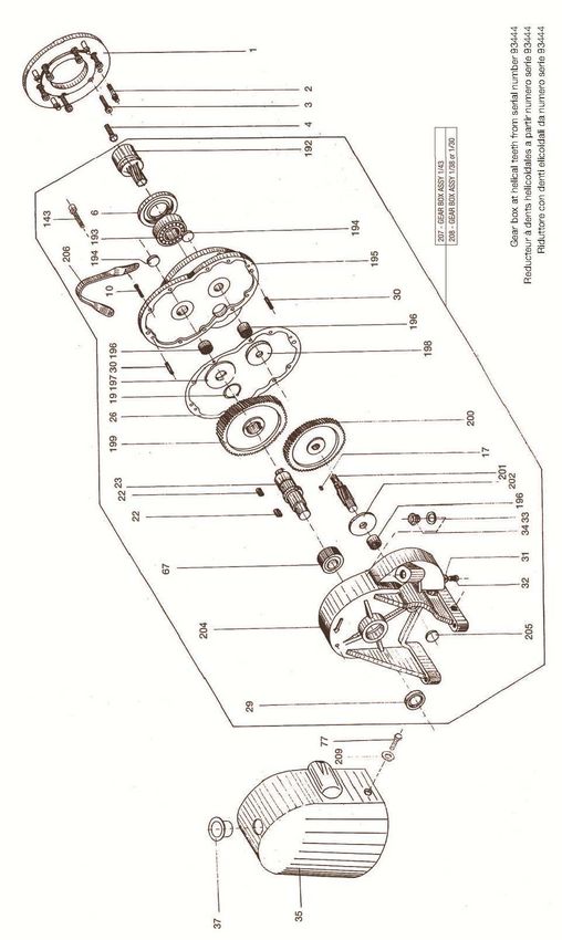
16 ESPLOSI / EXPLODED VIEWS
FIG.1-LB100
16ISTRUZIONI PER L'USO E MANUTENZIONE - INSTRUCTIONS FOR THE USE AND MAINTENANCE - LB80 - LB100
FIG.1-LB100
*
*: ART
17ISTRUZIONI PER L'USO E MANUTENZIONE - INSTRUCTIONS FOR THE USE AND MAINTENANCE - LB80 - LB100
FIG.2-LB100
18ISTRUZIONI PER L'USO E MANUTENZIONE - INSTRUCTIONS FOR THE USE AND MAINTENANCE - LB80 - LB100
FIG.2-LB100
*
*: ART
19ISTRUZIONI PER L'USO E MANUTENZIONE - INSTRUCTIONS FOR THE USE AND MAINTENANCE - LB80 - LB100
FIG.3:LB80 LB100
20ISTRUZIONI PER L'USO E MANUTENZIONE - INSTRUCTIONS FOR THE USE AND MAINTENANCE - LB80 - LB100
FIG.3:LB80 LB100
* *: ART
21ISTRUZIONI PER L'USO E MANUTENZIONE - INSTRUCTIONS FOR THE USE AND MAINTENANCE - LB80 - LB100
FIG.4-LB80
22ISTRUZIONI PER L'USO E MANUTENZIONE - INSTRUCTIONS FOR THE USE AND MAINTENANCE - LB80 - LB100
FIG.4-LB80
*
*: ART
23ISTRUZIONI PER L'USO E MANUTENZIONE - INSTRUCTIONS FOR THE USE AND MAINTENANCE - LB80 - LB100
FIG.5-LB80
24ISTRUZIONI PER L'USO E MANUTENZIONE - INSTRUCTIONS FOR THE USE AND MAINTENANCE - LB80 - LB100
FIG.5-LB80
*
Corpo pompa con bocche aspirazione e mandata e polmone filettati.
Pump case with threaded suction/delivery branches and air chamber
*
Corpo pompa con bocche e polmone flangiati.
Pump case with flanged branch and air chamber
*: ART
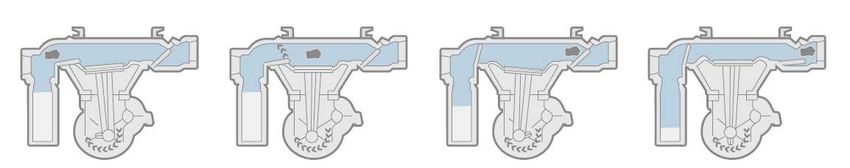
25ISTRUZIONI PER L'USO E MANUTENZIONE - INSTRUCTIONS FOR THE USE AND MAINTENANCE - LB80 - LB100 CARATTERISTICHE / FEATURES 26
ISTRUZIONI PER L'USO E MANUTENZIONE - INSTRUCTIONS FOR THE USE AND MAINTENANCE - LB80 - LB100

          Bocca di aspirazione.
   1
          Suction port.
          Ammortizzatore pneumatico per ridurre le pulsazioni nella tubazione di aspirazione.
   2
          Air cushion chamber to reduce pulsations in the suction line.
          Biella elastica di protezione contro il bloccaggio dovuto a corpi solidi o a sedimentazioni nel corpo pompa.
   3
          Spring coupling rod to protect against damage due to solids or sedimentation in the pump casing.
          Membrane e valvole in neoprene.
   4
          Neoprene diaphragm and valves.
          Bocca di mandata.
   5
          Delivery port.

                                                                                                                         27
VARISCO SpA
Terza Strada, 9 - Z.I. Nord - 35129 PADOVA - Italy
Tel. 049 82 94 111 - Fax 049 82 94 373
www.variscospa.com
Vendite Italia: Tel. 049 82 94 111 - Fax 049 82 94 373
italia@variscospa.com
International sales: Ph. +39 049 82 94 111 - Fax +39 049 80 76 762
export@variscospa.comPuoi anche leggere