EVO 3 MANUALE DI ISTRUZIONE E INSTALLAZIONE - INSTRUCTION AND INSTALLATION MANUAL
←
→
Trascrizione del contenuto della pagina
Se il tuo browser non visualizza correttamente la pagina, ti preghiamo di leggere il contenuto della pagina quaggiù
CODE REV. 2
SA671/681.xx 04/02/2019
EVO 3
MANUALE DI ISTRUZIONE E INSTALLAZIONE
INSTRUCTION AND INSTALLATION MANUAL
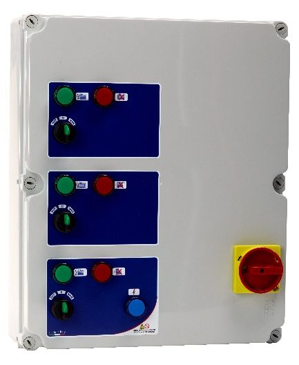
Quadro elettromeccanico avviamento diretto 3 motori
Direct starter electromechanical control panel 3 motors
ITA/ENG MADE IN ITALY
INDICE
INDEX

1. Istruzioni generali per l’installazione................... General instructions for installing...................3

2. Avvertenze......................................................... Warnings........................................................4

3. Caratteristiche generali ..................................... General characteristics..................................5

4. Caratteristiche elettriche e meccaniche............. Electrical and mechanical characteristics......6

5. Optional............................................................. Optional.........................................................7

6. Schema di collegamento SA671.xx.................... Wiring diagram SA671.xx...............................8

6. Schema di collegamento SA681.xx.................... Wiring diagram SA681.xx...............................9

7. Schema elettrico SA671.xx................................ Electrical diagram SA671.xx....................10-11

7. Schema elettrico SA681.xx................................ Electrical diagram SA681.xx...................12-13

8. Impiego.............................................................. Application................................................... 14

9. Funzionamento generale del quadro.................. General functioning of the control panel........14

10. Dichiarazione di conformita’............................. Declaration of conformity.............................15

                                                                     2
1. ISTRUZIONI GENERALI PER L’INSTALLAZIONE
1. GENERAL INSTRUCTIONS FOR INSTALLING

Assicurarsi che la linea sia protetta, secondo le         Make sure power supply is protected up to
normative, in funzione dell'applicazione.                 standard depending on application. The power
Accertarsi che la potenza e la corrente di targa          of the motor has to be within the control panel's
del motore rispecchino i limiti di impiego del            limits of use.
quadro.                                                   Install the control panel in an environment
Installare il quadro in ambienti adatti al suo            appropriate to its IP55 degree of protection.
grado di protezione IP55. Per il fissaggio                In order to fix the box, use the appropriate holes
dell'involucro, utilizzare gli appositi fori già          which are present or suggested on the bottom.
presenti o predisposti sul fondo. Nell'effettuare         Pay particular attention to not touching or
il fissaggio dell'involucro fare molta attenzione         damaging any components while fixing the box.
a non toccare o danneggiare i vari componenti.            Eliminate whatever metal and/or plastic
Eliminare qualsiasi tipo di impurità metallica e/o        impurity which could happen to fall inside the
plastica che dovesse casualmente cadere                   box (screws, washers, dust…).
all'interno dell'involucro (viti, rondelle,               When connecting electric cables, follow the
polvere…). Effettuare i collegamenti elettrici            wiring diagrams.
rispettando gli schemi di collegamento.                   When fixing the cables in the terminal board
Nel fissare i cavi sulle morsettiere, adoperare           use tools of correct size to avoid damaging the
attrezzi di giuste misure e dimensioni evitando           metal feed clamps and their sockets.
di danneggiare i morsetti metallici e le relative         Before acting upon anything inside, disconnect
sedi. Prima di qualsiasi operazione da                    power supply. Regulation procedures must be
effettuare all'interno, escludere l'alimentazione         carried out by qualified personnel. In case
generale.                                                 protections intervene verify the cause of the
Le operazioni di regolazione all'interno del              problem before resetting.
quadro devono essere svolte da personale                  If necessary substitute the various components
qualificato. In caso di intervento delle protezioni       only with those having the same characteristics
verificarne la causa prima del ripristino.                and components as the originals.
In caso di necessità sostituire i vari componenti
solo con altri aventi le stesse caratteristiche e
portate di quelli originali.                              It is the installer' s duty to verify the device
                                                          after the installation although it has already
È compito dell'installatore verificare                    undergone regular testing by the
l'apparecchiatura dopo l'installazione                    manufacturer.
nonostante questa sia già stata sottoposta
regolarmente a prove dal costruttore.                     The manufacturer is released from all
                                                          responsibilities for accidents to things or
Il costruttore declina ogni responsabilità                people, which derive from misuse of the
per sinistri a cose o persone dovuti a                    devices by unauthorized personnel or from
manomissioni delle apparecchiature da                     lack of maintenance and repair.
parte di personale non autorizzato o da
carenze nella manutenzione e riparazione.

                                                      3
2. AVVERTENZE
2. WARNINGS
SCOSSE ELETTRICHE ELECTRIC SHOCKS
Rischio di scosse elettriche se non osservate quanto Risk of electric shocks if not complied with the
prescritto. requirements.
PERICOLO DANGER
Rischio di danni alle persone, e alle cose se non Risk of personal injury and property if not complied
osservate quanto prescritto. with the requirements.
AVVERTENZA WARNING
Prima di installare e utilizzare il prodotto leggere Before installing and using the product read this book
attentamente il presente manuale in tutte le sue parti. in all its parts. Installation and maintenance must be
L'installazione e la manutenzione devono essere performed by qualified personnel in accordance with
eseguite da personale qualificato nel rispetto delle current regulations.
norme vigenti. The manufacturer will not be held responsible for any
Il costruttore non risponde di danni provocati da un uso damage caused by improper or prohibited use of this
improprio o proibito del quadro e declina ogni control panel and is not responsible for any damages
responsabilità per danni provocati da una non corretta caused by an incorrect installation or maintenance of
installazione e manutenzione dell’impianto. L'uso di the plant. The use of non-original spare parts,
ricambi non originali, manomissioni o usi impropri tempering or improper use, make the product warranty
fanno decadere la garanzia. null.
AVVERTENZA WARNING
Accertarsi che la potenza di targa del motore sia Be sure that the power of the motor is within the control
all'interno dei limiti di impiego del quadro. panel range.
Installare il quadro in ambienti idonei al suo grado di Install the control panel in an environment appropriate
protezione IP55. to its IP55 degree of protection.
Per l'intervento all'interno del quadro usare attrezzi To operate inside the control panel use tools of correct
adeguati per evitare danni alle morsettiere. size to avoid damaging the sockets.
PERICOLO DANGER
Prima di ogni intervento accertarsi che il quadro sia Before any intervention ensure that the control panel is
scollegato dall'alimentazione elettrica. disconnected from the electricity supply.
Non effettuare manovre con Il quadro aperto. Do not attempt operations when the control panel is
Il quadro deve essere collegato ad un efficiente open.
impianto di terra. The control panel must be connected to an efficient
Per il fissaggio del quadro usare gli appositi fori, non earthing system.
danneggiare i componenti interni ed eliminare In order to fix the box use the appropriate holes present
eventuali detriti di lavorazione all'interno del quadro. on the bottom, don't damage internal components and
In caso di intervento delle protezioni eliminare la causa eliminate any working debris inside the box.
del malfunzionamento prima di effettuare il ripristino. In the case of protections eliminate the cause of the
malfunction before the restoration.
43. CARATTERISTICHE GENERALI
3. GENERAL CHARACTERISTICS
- Tensione d'alimentazione 230 Vac ± 10% - Power supply 230 Vac ± 10% (SA671.xx)
(SA671.xx) - Power supply 400 Vac ± 10% (SA681.xx)
- Tensione d'alimentazione 400 Vac ± 10% - Operating frequency 50/60 Hz
(SA681.xx) - General disconnecting switch with door
- Frequenza di lavoro 50/60 Hz lock
- Sezionatore generale con blocca porta - N°2 switches for automatic -0- manual
- N°3 selettori per il funzionamento operation
automatico -0- manuale - N°2 very low voltage inputs for pressure
- N°2 ingressi in bassissima tensione per switch or float switches (motor 1)
pressostato o galleggianti (motore 1) - N°2 very low voltage inputs for pressure
- N°2 ingressi in bassissima tensione per switch or float switches (motor 2)
pressostato o galleggianti (motore 2) - N°2 very low voltage inputs for pressure
- N°2 ingressi in bassissima tensione per switch or float switches (motor 3)
pressostato o galleggianti (motore 3) - N°3 running indicators
- N°3 spie marcia - N°3 overload indicators
- N°3 spie sovraccarico - Mains indicators
- Spia presenza rete - Auxiliary circuit protection fuse
- Fusibile di protezione circuito ausiliario - Transformer for auxiliary circuit output
- Trasformatore per circuito ausiliario uscita 24Vac
24Vac - Protection fuse on each motor
- Fusibile di protezione su ogni motore - N°3 contactors
- N°3 contattori - N°3 thermal relays (internal reset)
- N°3 relè termici ripristinabili internamente - Terminal board for auxiliary control
- Morsettiera per comando ausiliario e - External termoplastic box
potenza - Cable holder
- Contenitore esterno in materiale - Protection degree Ip55
termoplastico - Operating temperature -5/+40°C
- Pressacavi
- Grado di protezione Ip55
- Temperatura d'impiego -5/+40°C
54. CARATTERISTICHE ELETTRICHE E MECCANICHE (SA671.xx,SA681xx)
4. ELECTRICAL AND MECHANICAL CHARACTERISTICS (SA671.xx,SA681xx)
SINGLE-PHASE 230Vac ±10%
CODE POWER OPERATING DIMENSIONS WEIGHT
KW HP CURRENT A B C Kg
SA671.00/01 0,37/0,55 0,5/0,75 3x(4,5-6,3) 460 380 150 10
SA671.02 0,75 1 3x(7-10) 460 380 150 10
SA671.03 1,1 1,5 3x(9-12,5) 460 380 150 10
SA671.04 1,5 2 3x(11-16) 460 380 150 10
SA671.05 2,2 3 3x(14-20) 460 380 150 10
THREE-PHASE 400Vac ±10%
CODE POWER OPERATING DIMENSIONS WEIGHT
KW HP CURRENT A B C Kg
SA681.00 0,37 0,5 3x(1,1-1,6) 460 380 150 10
SA681.01 0,55 0,75 3x(1,4-2) 460 380 150 10
SA681.02 0,75 1 3x(1,8-2,5) 460 380 150 10
SA681.03/04 1,1/1,5 1,5/2 3x(2,8-4) 460 380 150 10
SA681.05/06 1,8/2,2 2,5/3 3x(4,5-6,3) 460 380 150 10
SA681.07/08 3/3,7 4/5 3x(7-10) 460 380 150 10
SA681.09 4 5,5 3x(9-12,5) 460 380 150 10
SA681.10 5,5 7,5 3x(11-16) 460 380 150 10
SA681.11 7,5 10 3x(14-20) 460 380 150 10,5
SA681.12 9,2 12,5 3x(20-25) 460 380 150 10,5
SA681.13 11 15 3x(23-28) 460 380 150 10,5
SA681.14 13 17,5 3x(27-32) 460 380 150 10,5
65. OPTIONAL
5. OPTIONALS
CODE TYPE
OP100.04 Relè mancanza e sequenza fasi / Lack and sequence of phases relay
OP100.04/1 Relè mancanza e sequenza fasi, minima e massima tensione /
Lack and sequence of phases relay, minimum and maximum voltage
OP100.04/2 Relè mancanza e sequenza fasi, minima e massima tensione e asimmetria /
Lack and sequence of phases relay, minimum and maximum voltage and asymmetry
OP100.04/3 Relè minima e massima tensione monofase /
Single-phase minimum and maximum voltage relay
OP100.05 Scaricatore monofase di tipo 2 per sovratensione / Single-phase surge arrester type 2
OP100.05/1 Scaricatore trifase di tipo 2 per sovratensione / Three-phase surge arrester type 2
OP100.15/24 Contaore 24Vac 48x48 / Hour counter 24Vac 48x48
OP100.03/20 Condensatore 20μF cablato* / Wired capacitor 20μF*
OP100.03/30 Condensatore 30μF cablato* / Wired capacitor 30μF*
OP100.03/40 Condensatore 40μF cablato* / Wired capacitor 40μF*
OP100.03/50 Condensatore 50μF cablato* / Wired capacitor 50μF*
OP100.03/70 Condensatore 70μF cablato* / Wired capacitor 70μF*
OP100.19 Modulo GSM / GSM module
OP100.18 Timer ritardo avviamento / Start delay timer
OP100.18/1 Timer multifunzione / Multifunction timer
OP100.16 Timer analogico giornaliero 72x72 con riserva / Analog daily timer 72x72 with reserve
OP100.16/1 Timer analogico giornaliero 72x72 senza riserva / Analog daily timer 72x72 without reserve
OP100.16/2 Timer analogico giornaliero DIN con riserva / Analog daily timer DIN with reserve
OP200.21 Kit pressurizzazione 3 motori / Pressurization kit 3 motors
OP200.31 Kit acque reflue 3 motori / Sewage kit 3 motors
OP100.02/1 Pulsante start/stop cablato / Wired start/stop button
OP100.13 Pulsante "STOP" sirena / Siren "STOP" button
OP100.13/1/24 Sirena cablata 24Vac/dc / Wired siren 24Vac/dc
OP100.13/2/24 Lampeggiante cablato 24Vac/dc / Wired flashing lamp 24Vac/dc
OP100.14/24 Lampeggiante con sirena remoto 24Vac/dc / Remote flashing lamp with siren 24Vac/dc
OP200.01 Uscita allarme 24Vac + contatto puro / Alarm output 24Vac + pure contact
* Condensatori da 10μF, 16μF, 25μF, 35μF, 45μF, 55μF, 60μF, 65μF, 75μF e 80μF a richiesta.
L'inserimento di optionals può comportare variazioni alle dimensioni del quadro.
Per ulteriori dettagli contattare il n/s ufficio tecnico/commerciale.
* Capacitors from 10μF, 16μF, 25μF, 35μF, 45μF, 55μF, 60μF, 65μF, 75μF and 80μF on request.
The addition of some optional can imply changes in the size of the control panel.
For further details please contact our technical/commercial department.
76. SCHEMA DI COLLEGAMENTO SA671.xx
6. WIRING DIAGRAM SA671.xx
X-11
X-10
X-12
X-1
X-2
X-3
X-4
X-5
X-6
X-7
X-8
X-9
U1
U2
U3
V1
V2
V3
M M M
1 1 1 L N
ALIMENTAZIONE
MOTORE 1 MOTORE 2 MOTORE 3 POWER SUPPLY
MOTOR 1 MOTOR 2 MOTOR 3 230Vac 50/60Hz
LEGENDA KEY
X1-X2 PRESSOSTATO O GALLEGGIANTE MINIMO (MOT1) X1-X2 PRESSURE SWITCH OR MINIMUM FLOAT SWITCH (MOT1)
X3-X4 GALLEGGIANTE MASSIMO (MOT1) X3-X4 MAXIMUM FLOAT SWITCH (MOT1)
X5-X6 PRESSOSTATO O GALLEGGIANTE MINIMO (MOT2) X5-X6 PRESSURE SWITCH OR MINIMUM FLOAT SWITCH (MOT2)
X7-X8 GALLEGGIANTE MASSIMO (MOT2) X7-X8 MAXIMUM FLOAT SWITCH (MOT2)
X9-X10 PRESSOSTATO O GALLEGGIANTE MINIMO (MOT3) X9-X10 PRESSURE SWITCH OR MINIMUM FLOAT SWITCH (MOT3)
X11-X12 GALLEGGIANTE MASSIMO (MOT3) X11-X12 MAXIMUM FLOAT SWITCH (MOT3)
Max 10 mm² Max 6 mm² Max 6 mm²
(M4)
10 mm 0,8Nm 10 mm 2,5Nm 10 mm 0,5Nm
86. SCHEMA DI COLLEGAMENTO SA681.xx
6. WIRING DIAGRAM SA681.xx
X-11
X-10
X-12
X-1
X-2
X-3
X-4
X-5
X-6
X-7
X-8
X-9
W1
W2
W3
V1
V2
V3
U1
U2
U3
M M M
3 3 3 R S T
MOTORE 1 MOTORE 2 MOTORE 3 ALIMENTAZIONE
MOTOR 1 MOTOR 2 MOTOR 3 POWER SUPPLY
400Vac 50/60Hz
LEGENDA KEY
X1-X2 PRESSOSTATO O GALLEGGIANTE MINIMO (MOT1) X1-X2 PRESSURE SWITCH OR MINIMUM FLOAT SWITCH (MOT1)
X3-X4 GALLEGGIANTE MASSIMO (MOT1) X3-X4 MAXIMUM FLOAT SWITCH (MOT1)
X5-X6 PRESSOSTATO O GALLEGGIANTE MINIMO (MOT2) X5-X6 PRESSURE SWITCH OR MINIMUM FLOAT SWITCH (MOT2)
X7-X8 GALLEGGIANTE MASSIMO (MOT2) X7-X8 MAXIMUM FLOAT SWITCH (MOT2)
X9-X10 PRESSOSTATO O GALLEGGIANTE MINIMO (MOT3) X9-X10 PRESSURE SWITCH OR MINIMUM FLOAT SWITCH (MOT3)
X11-X12 GALLEGGIANTE MASSIMO (MOT3) X11-X12 MAXIMUM FLOAT SWITCH (MOT3)
Max 10 mm²
Max 6 mm² Max 6 mm²
(M4)
10 mm 0,8Nm 10 mm 2,5Nm 10 mm 0,5Nm
97. SCHEMA ELETTRICO (SA651.xx)
7. ELECTRICAL DIAGRAM (SA651.xx)
107. SCHEMA ELETTRICO (SA651.xx)
7. ELECTRICAL DIAGRAM (SA651.xx)
117. SCHEMA ELETTRICO (SA661.xx)
7. ELECTRICAL DIAGRAM (SA661.xx)
127. SCHEMA ELETTRICO (SA661.xx)
7. ELECTRICAL DIAGRAM (SA661.xx)
138. IMPIEGO
8. APPLICATION
EVO3 è un quadro con apparecchiatura EVO 3 is a control panel with electromechanical
elettromeccanica. equipment.
Può essere utilizzato per qualsiasi tipo di It can be used for any type of application that
applicazione che necessita un avviamento requires a direct starting of two motors.
diretto di due motori.
9. FUNZIONAMENTO GENERALE DEL QUADRO
9. GENERAL OPERATION OF THE CONTROL PANEL
E’ possibile far funzionare il quadro EVO 3 It is possible to operate the EVO 3 control panel
secondo due modalità: in two ways:
- Automatica - Automatic
In questa condizione il quadro avvia il motore In this condition the control panel starts the
solo se i pressostati o interruttori a galleggiante motor only if the pressure switches or float
si trovano su ON. switches are ON.
- Manuale - Manual
In questa condizione il quadro avvia il motore In this condition the control panel starts the
fino al rilascio del selettore escludendo il motor until the selector is released bypassing
controllo sui pressostati o interruttori a the control over the pressure switches or float
galleggiante. switches.
Il corretto funzionamento (motore in marcia) è The correct operation (motor running) is
indicato dalla spia verde . indicated by the green light.
Il malfunzionamento (motore in sovraccarico) è The malfunction (motor overload) is indicated
indicato dalla spia rossa. In questa condizione, by the red light. In this condition, the contactor
il contattore si sgancia ed il motore non verrà is opened and the motor will no longer be fed.
più alimentato. To restore the proper operation, press the reset
Per ripristinare il corretto funzionamento, button in the thermal of the motor.
premere il tasto reset nella termica del motore.
1410. DICHIARAZIONE DI CONFORMITÁ
10. DECLARATION OF CONFORMITY
Il costruttore: The manufacturer:
Salupo S.a.s. Salupo S.a.s.
Via Laganeto, 129 Via Laganeto, 129
98070 Rocca di Capri Leone (ME) 98070 Rocca di Capri Leone (ME)
Dichiara che: Declares that:
gli avviatori diretti EVO 3 Monofase e Trifase the Single-phase and Three-phase EVO 3
direct starters
sono conformi ai requisiti di protezione in
materia di sicurezza (bassa tensione) e di comply with the specific protection
compatibilità elettromagnetica specifici previsti prerequisites concerning both safety (low
dalle Direttive della Comunità Europea voltage) and the electromagnetic compatibility
2006/95/CEE del 16 Gennaio 2007, provided for by the European Community laws
2004/108/CE del 10 Novembre 2007, 2006/95/CEE of 16th January 2007,
93/68/CEE del 22 Luglio 1993. Conformità 2004/108/CE of 10th November 2007,
CEI EN61439-1, EN 61000-6-3, EN 61000-6-1 93/68/CEE of 22th July 1993. Compliance
DIN VDE 0113/EN60204-1 / IEC 204-1. CEI EN61439-1, EN 61000-6-3, EN 61000-6-1
DIN VDE 0113/EN60204-1 / IEC 204-1.
SALUPO S.A.S. SALUPO S.A.S.
Responsabile Ufficio Tecnico Technical Dep. Manager
P.I. Salupo Ivan P.I. Salupo Ivan
15SALUPO
Via Laganeto, 129
98070 Rocca di Caprileone (ME) ITALY
Tel.:+39 - (0) 941 - 950216
Fax:+39 - (0) 941 - 958777
www.salupoquadri.com
e-mail: salupo@salupoquadri.com
UNI EN ISO 9001:2008Puoi anche leggere