HOLA - Designed special for you - MANUALE TECNICO TECHNICAL MANUAL
←
→
Trascrizione del contenuto della pagina
Se il tuo browser non visualizza correttamente la pagina, ti preghiamo di leggere il contenuto della pagina quaggiù
MANUALE TECNICO
         TECHNICAL MANUAL

       HOLA
           L - LS - LSP

Creata apposta per te
  Designed special for you

          venitem.com
I TA
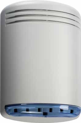
Descrizione sirena mod. Hola L: sirena autoalimentata 12 Vdc con lampeggiante a led ad alta luminosità e
basso assorbimento – doppio tamper antiapertura e rimozione – programmazione suono e temporizzazione
– conteggio allarmi – autocontrollo a microprocessore di: batteria e speaker con relativa uscita negativa di
anomalia – programmazione di comando sirena e lampeggiante separati – ingresso reset lampeggiante –
segnalazione ottica ON-OFF impianto istantanea e permanente – circuito elettronico protetto da inversioni
di polarità e tropicalizzato in resina ad immersione.
Descrizione sirena mod. Hola LS: Caratteristiche tecniche come Hola L con sistema antischiuma e
antishock a doppio micro contro gli urti violenti.
Descrizione sirena mod. Hola LSP: Caratteristiche tecniche come Hola L con circuito antischiuma e
antishock a doppio micro e antiperforazione.
Fig. 1
N.B. Per aprire la sirena svitare la vite presente
sotto la calotta, procedendo prima alla rimozione
di questa facendo leva con un cacciavite nella
fessura tra calotta e coperchio come in Fig. 1.
2
info@venitem.comSCHEMA DI COLLEGAMENTO
A – COLLEGAMENTO A DUE CONDUTTORI.
Collegare l’alimentazione 13,8 Vdc proveniente dalla centrale ai rispettivi morsetti:
n°1 negativo; n°2 positivo. (il comando n° 3 va ponticellato al positivo n° 2 )
N.B. DA FABBRICA DIP-SWITCH N°3 OFF POSITIVO A MANCARE
B – COLLEGAMENTO A TRE CONDUTTORI.
Collegare l’alimentazione 13,8 Vdc proveniente dalla centrale ai rispettivi morsetti:
n°1 negativo; n°2 positivo; n°3 comando positivo a mancare.
N.B. DA FABBRICA DIP-SWITCH N°3 OFF POSITIVO A MANCARE
C – SEGNALAZIONE OTTICA DI STATO IMPIANTO (ON-OFF ISTANTANEO E PERMANENTE).
•Portando un positivo al morsetto n°4 tutti i led del lampeggiante eseguono 3 lampeggi (ON);
•Togliendo il positivo tutti i led rimangono accesi fissi per 5 secondi (OFF).
Dip-switch 10 in OFF DA FABBRICA (Situazione istantanea di ON-OFF)
Dip-switch 10 in ON (Situazione istantanea di ON-OFF con permanenza di un led intermittente per il tempo
in cui c’è tensione positiva al morsetto n°4).
D – FUNZIONI LAMPEGGIANTE
Da fabbrica il lampeggiante segue il comando della sirena e si spegne al ritorno del comando (DIP-SWITCH
5 OFF - 6 OFF). Per attivare le altre funzioni basta portare o togliere una tensione negativa al morsetto n°5
e modificare i Dip-switch 5 e 6 a seconda dell’esigenza (vedi tabella selezione lampeggiante).
E – TEMPORIZZAZIONE SIRENA.
Da fabbrica la temporizzazione è di 3 minuti (DIP-SWITCH 1OFF – 2 OFF) e può essere modificata a 5-10
minuti o infinito (vedi tabella temporizzazione sirena).
F – MORSETTO N°6 INGRESSO POSITIVO DI BLOCCO SUONATA (OPTIONAL FORNITO SOLO SU
RICHIESTA)
Attiva il relé di interruzione suono portando un segnale positivo al morsetto n°6.
G – MORSETTO N°7 USCITA DI ANOMALIA E LED ANOMALIA.
La sirena Hola è gestita da un microprocessore in grado di controllare la batteria e lo speaker; in caso di
anomalia invia un segnale negativo open-collector al morsetto n°7 mentre il led di controllo presente nel
circuito sirena indica il tipo di guasto a seconda del numero di lampeggi seguiti da una breve pausa.
Il microprocessore esegue automaticamente ogni 32 giorni il test di corrente batteria e in caso di non
superamento invia un’uscita di anomalia negativa continua se l’impianto è acceso (+12 Vdc al morsetto
n°4); mentre se l’impianto è spento (senza tensione al morsetto n°4) invia 3 impulsi negativi e il led di
anomalia esegue 3 lampeggi seguiti da una breve pausa. Inoltre il microprocessore stesso si autocontrolla in
ogni istante e nel caso di guasto o mal funzionamento dà un’uscita negativa continua con blocco del suono
sia che l’impianto sia acceso o spento.
3
info@venitem.comTABELLA DI SEGNALAZIONE ANOMALIE IMPIANTO ACCESO IMPIANTO SPENTO LED ROSSO ANOMALIA
I TA
USCITA N°7 ANOMALIA USCITA N°7 ANOMALIA IMPIANTO ACCESO/
SPENTO
INTERRUZIONE SPEAKER A RIPOSO USCITA NEGATIVA FISSA 6 IMPULSI NEGATIVI 6 LAMPEGGI
DRIVER SIRENA DANNEGGIATI USCITA NEGATIVA FISSA 4 IMPULSI NEGATIVI 4 LAMPEGGI
BATTERIA GUASTA (test che si effettua ogni 32 giorni) USCITA NEGATIVA FISSA 3 IMPULSI NEGATIVI 3 LAMPEGGI
BATTERIA INSUFFICIENTE USCITA NEGATIVA FISSA 2 IMPULSI NEGATIVI 2 LAMPEGGI
BATTERIA INSUFFICIENTE (test sempre presente con soglia di USCITA NEGATIVA FISSA 1 IMPULSO NEGATIVO 1 LAMPEGGIO
riferimento sotto i 9V)
Le segnalazioni di anomalie riportate nella tabella rimangono in memoria fino a che si presentano i seguenti
casi:
1) mancanza del comando (mancanza del positivo/negativo al morsetto n°3);
2) accensione dell’impianto (invio +12 Vdc al morsetto n°4);
3) invio di un negativo al morsetto n°5.
H – COLLEGAMENTO TAMPER ANTISTRAPPO E RIMOZIONE COPERCHIO
Collegare ai morsetti n°8 e 9 la linea tamper proveniente dalla centrale.
I – MORSETTI N°10 E N°11 USCITA NC DI ANTIPERFORAZIONE (da usare solo nella versione LSP).
Collegare in serie alla linea tamper della sirena (morsetti n°8 e n°9)
SCHEMA ELETTRICO DI COLLEGAMENTO
1 Alimentazione negativa - 0V GND
2 Alimentazione positiva +13,8 Vdc
3 Ingresso comando (start)
4 Ingresso ON-OFF
5 Ingresso comando lamp. o reset lamp.
6 Ingresso blocco suonata (optional inseribile solo dafabbrica)
7 Uscita negativa anomalia
8
9 } Tamper NC
10
11
} Uscita di antiperforazione relè NC 1A
4
info@venitem.comCollegamento a due fili
I TA
Linea tamper da centrale
Linea tamper da centrale
CENTRALE
Positivo ricarica/comando +13,8 Vdc
Negativo ricarica
Collegamento a tre fili
CENTRALE
Comando positivo a mancare
Positivo di ricarica + 13,8 Vdc
Negativo ricarica
Collegamento Tamper Hola LSP
Linea tamper da centrale
CENTRALE
Ponticello
Linea tamper da centrale
5
info@venitem.comCONSIGLI PER L’INSTALLAZIONE:
I TA
Nel caso di funzionamento anomalo della sirena verificare se il Led presente sulla scheda lampeggia.
Se lampeggia controllare la tabella di segnalazioni anomalie.
Nel caso di utilizzo del comando di ON/OFF anche per altri apparecchi collegare sul morsetto 4 un diodo
1N4007.
Per avere la segnalazione di attivazione impianto tramite uscita open collector, configurare l’uscita attiva a
centrale spenta ed effettuare il seguente collegamento:
CENTRALE
NB: Per evitare la formazione di
+12Vdc
condensa nella sirena si deve
impedire qualsiasi flusso d’aria nella SIRENA 1k
canalina. Una volta passati i cavi 1/4w
sigillare il foro con del silicone o un
altro stucco. Questa operazione evita M4
Open
che, durante il periodo invernale, l’aria Uscita collector
calda e umida che esce dall’edificio attiva a
centrale
attraverso il passaggio vada a formare spenta
condensa nella sirena precludendo il
corretto funzionamento di questa.
CARATTERISTICHE TECNICHE HOLA
Tensione Nominale di Alimentazione 13,8 Vdc
Comando minimo 4,5 Vdc
Alimentazione minima 10.5 Vdc
Alimentazione massima 15.5 Vdc
Corrente Assorbimento suono 1,44 A
Assorbimento lampeggiante 100 mA
Attesa 15 mA
Frequenza fondamentale U 1625 Hz
Pressione sonora U 105(A) 3 mt.
Grado di protezione U IP 44
Condizioni ambientali esterne U Da –25° a +55° C
Temporizzazione U Programmabile
Capacità della batteria U 12V 1,2Ah o 12V 2.2 Ah massimo
Comando della centrale U 2 o 3 fili
Dimensioni U 335x220x85 (H x L x P)
Peso U 1,990 gr
CERTIFICAZIONI
Hola: Conforme EN 50131-4
GARANZIA
Tutti i prodotti Venitem sono garantiti contro i difetti di fabbricazione o di materiale. Nell’intento di migliorare
il design e la qualità dei propri prodotti la ditta Venitem si riserva di modificare il prodotto senza alcun
preavviso. Tutti i prodotti guasti o difettosi vanno resi al proprio fornitore.
6
info@venitem.comSETTAGGIO DIP-SWITCH
1 - TEMPORIZZAZIONE SIRENA.
DIP 1 2
OFF OFF 3 MINUTI (DA FABBRICA)
OFF ON 5 MINUTI
ON OFF 10 MINUTI
ON ON INFINITO
2 - SELEZIONE COMANDO
DIP 3
OFF POSITIVO A MANCARE (DA FABBRICA)
ON NEGATIVO A MANCARE
3 - CONTEGGIO ALLARMI GIORNALIERI
DIP 4
OFF ALLARMI INFINITI (DA FABBRICA)
LIMITAZIONE A 4 ALLARMI GIORNALIERI (ogni allarme viene
ON conteggiato se la sua durata è di almeno 30 secondi)
4 - SELEZIONE LAMPEGGIANTE
DIP 5 6
PARTE CON IL COMANDO E
OFF OFF SI SPEGNE CON IL COMANDO
(DA FABBRICA)
PARTE CON IL COMANDO E
ON OFF SI SPEGNE CON LA SIRENA
PARTE CON IL COMANDO E
OFF ON SI SPEGNE CON IL RESET
PARTE CON IL RESET E SI
ON ON SPEGNE CON IL RESET
5 - SELEZIONE SUONI (4 TIPOLOGIE)
DIP 7 8
FREQUENZA FONDAMENTALE
1625Hz
(DA FABBRICA)
OFF OFF
F. MIN F. MAX
1600Hz PERDITA
ON OFF 1400Hz CERTIFICAZIONE IMQ
1800Hz PERDITA
OFF ON 900Hz CERTIFICAZIONE IMQ
MODULAZIONE DUTY CYCLE
ON ON 1250Hz PERDITA CERTIFICAZIONE
IMQ
6 - SELEZIONE LED STATO IMPIANTO
DIP 9 10
ATTIVA 1 LED DI
LIBERO ON PERMANENZA STATO
IMPIANTO
NON ATTIVA 1 LED DI
LIBERO OFF PERMANENZA STATO
IMPIANTO (DA FABBRICA)
7
info@venitem.comENG
Description of the sounder mod. Hola L: Self-supplied 12 Vdc sounder with highly luminous led and
low consumption – double tamper for anti-opening and removal – sound programming and temporization
– alarms counting – microprocessor automatic control of batteries and speaker and concerned anomaly
outputs – programming of separate sounder command and light – input for lamp reset – optical indication
of immediate and permanent system ON/OFF – electronic circuit protected against polarity inversion and
tropycalized by resin immersion.
Description of the sounder mod. Hola LS: Technical features as per Hola L with anti-foam with double
micro switch and antishock device.
Description of the sounder mod. Hola LSP: Technical features as per Hola L, with anti-foam and antishock
circuit with double micro switch and with anti- drilling device.
Pic. 1
Note: In order to open the sounder remove the led
cover twisting a screw-driver between the led-
cover and the sounder-cover as shown in the
Pic. 1.
8
info@venitem.comCONNECTION SCHEME
ENG
A – TWO-WIRES CONNECTION
Connect supplying 13,8 Vdc coming from control panel to the corresponding terminals:
n°1 negative; n°2 positive. (command n° 3 must be connected by jumper to positive n° 2 )
Note: by-default DIP-SWITCH N°3 OFF with missing positive
B – THREE-WIRES CONNECTION
Connect supplying 13,8 Vdc coming from control panel to corresponding terminals:
n°1 negative; n°2 positive; n°3 missing positive command
Note: by-default DIP-SWITCH N°3 OFF with missing positive
C – OPTICAL INDICATION OF SYSTEM STATUS (ON-OFF IMMEDIATE OR PERMANENT)
•Taking a positive to terminal n° 4 all Leds blink 3 times (ON);
•Removing positive all Led stay lightened up steadily for 5 seconds (OFF)
Dip-switch 10 in OFF BY DEFAULT (Immediate ON-OFF situation)
Dip-switch 10 in ON (Immediate ON-OFF situation with persisting of one intermittent led during presence
of positive tension at terminal n° 4).
D – FLASHING UNIT FUNCTIONS
By default the lamp follows up the sounder command and switches off when the command is back (DIP-
SWITCH 5 OFF - 6 OFF). In order to activate other functions take or remove negative tension to terminal n°5
and modify Dip-switch 5 and 6 according to need (see the chart for flashing selection).
E – SOUND TEMPORIZATION
By default temporization is 3 minutes (DIP-SWITCH 1 OFF – 2 OFF) and can be modified to 5-10 minutes
or infinite (see chart of sounder timing).
F – TERMINAL N. 6 POSITIVE INPUT OF SOUND BLOCK (OPTIONAL, AVAILABLE ON REQUEST)
It activates the relay of sound interruption taking a positive signal + 12Vdc to terminal n. 6
G – TERMINAL N°7 ANOMALY OUTPUT AND ANOMALY LED .
The HOLA sounder is controlled by a microprocessor capable to control battery and speaker; in case of
anomaly it sends a negative open-collector signal to terminal n° 7 whilst the control Led on the sounder
circuit shows the type of failure by a certain number of blinks followed by a short pause.
The microprocessor automatically carries out the battery test every 32 days and in case of negative result
it sends out an output of continuous negative anomaly if the system is ON (+12Vdc to terminal n° 4) whilst
it sends out 3 negative pulses if the system is OFF and the anomaly Led blinks 3 times followed by a short
pause. Furthermore the microprocessor controls itself anytime and in case of failure or mal-functioning
gives a negative continuous output with sound block with both on or off system.
9
info@venitem.comCHART OF ANOMALIES SYSTEM ON SYSTEM OFF ANOMALY RED LED
ENG
ANOMALY OUTPUT N° 7 ANOMALY OUTPUT N° 7 SYSTEM ON OR OFF
AND SIGNALLING
STAND-BY SPEAKER INTERRUPTION STEADY NEGATIVE OUTPUT 6 NEGATIVE IMPULSES 6 FLASHINGS
DAMAGED SIREN DRIVER STEADY NEGATIVE OUTPUT 4 NEGATIVE IMPULSES 4 FLASHINGS
BATTERY FAILURE (every 32 days test) STEADY NEGATIVE OUTPUT 3 NEGATIVE IMPULSES 3 FLASHINGS
LOW BATTERY STEADY NEGATIVE OUTPUT 2 NEGATIVE IMPULSES 2 FLASHINGS
LOW BATTERY (omnipresent test with threshold under 9V) STEADY NEGATIVE OUTPUT 1 NEGATIVE IMPULSE 1 FLASH
The anomaly indications shown in the chart are kept in memory until the following situations occur:
1) Command missing (positive/negative missing to terminal n° 3);
2) System arming ( +12V sending Vdc to terminal n°4);
3) Negative sending to terminal n°5.
H – CONNECTION OF ANTI-REMOVAL AND ANTI-OPENING TAMPER
Connect the tamper input coming from control panel to terminals n° 8 and 9
I – TERMINALS NO.10 AND NO. 11 ANTI-DRILLING NC OUTPUT (only Hola LSP model).
To connect in series to the sounder tamper line. (Terminal n. 8 and n. 9)
ELECTRICAL CONNECTION SCHEME
1 Negative power supply -0V GND
2 Positive power supply +13,8 Vdc
3 Control input (start)
4 ON-OFF input
5 Flashing control/reset input
6 Sound block input (to be insered by manufacturer on request)
7 Negative output of anomaly
8
9 } Tamper NC
10
11
} Anti-drilling
Relay NC 1A
output
10
info@venitem.comConnection with two wires
ENG
Tamper line from control panel
Tamper line from control panel
CONTROL PANEL
Control/Recharging Positive +13,8 Vdc
Recharging Negative
Connection with three wires
CONTROL PANEL
Positive control
Recharging Positive +13,8 Vdc
Recharging Negative
Hola LSP Tamper line connection
CONTROL PANEL
Tamper line from control panel
Jumper
Tamper line from control panel
11
info@venitem.comADVISE TO THE INSTALLER:
In case of malfunctioning of the sounder check if the Led on board is flashing. If it does, check the chart of
anomalies indications.
In case of use of ON/OFF command also for other devices connect a diode IN4007 to terminal 4.
In order to have the indication of armed system by an open collector output, configure the output active
when the system is disarmed and make the following connection:
ALARM PANEL
Note: in order to avoid formation of
+12Vdc
condensation inside the sounder, any
air flow must be avoided. Once the SOUNDER 1k
cables have been connected, seal the 1/4w
hole by use of silicon. This operation
will prevent the warm and humid air M4
Open
of the building to form condensation Active collector
inside the sounder during winter output
at disarmed
time, thus avoiding the risk of system
malfunctioning.
HOLA TECHNICAL FEATURES
Tension Nominal Power Supply 13,8 Vdc
Minimum Control 4,5 Vdc
Minimum Supply 10.5 Vdc
Maxim Supply 15.5 Vdc
Current Sound consumption 1,44 A
Flashing consumption 100 mA
Stand-by 15 mA
Frequency U 1625 Hz
Sound Level U 105 dB (A) 3 meters
Protection Level U IP 44
Operating temperature U From -25° a +55° C
Timer U Programmable
Battery U 12V 1,2Ah or 12V 2.2 Ah max
Command from the mains U 2 or 3 wires
Dimensions U 335x220x85 (H x L x D)
Weight U 1,990 g
CERTIFICATION
HOLA: Incert for Belgium
Complying to EN 50131-4 Standard
WARRANTY
All Venitem products are guaranteed AGAINST manufacturing or components defects. With the aim of
improving design and quality of its products, Venitem retains the right to modify the products without any
previous notice. All defective or failed products have to be returned to the usual supplier.
12
info@venitem.comDIP-SWITCH SETTING
ENG
1 - SOUNDER TIMING
DIP 1 2
OFF OFF 3 MINUTES (BY DEFAULT)
OFF ON 5 MINUTES
ON OFF 10 MINUTES
ON ON INFINITE
2 - COMMAND SELECTION
DIP 3
OFF POSITIVE (BY DEFAULTS)
ON NEGATIVE
3 - DAILY ALARM COUNTING
DIP 4
OFF INFINITE ALLARM (BY DEFAULT)
LIMITATION TO 4 DAILY TO ALARMS
ON (only alarms of over 30 seconds are considered)
4 - FLASHING SELECTION
DIP 5 6
COMMAND ACTIVATING AND
OFF OFF DE-ACTIVATING (BY DEFAULT)
ON OFF COMMAND ACTIVATING AND
SOUNDER DE-ACTIVATING
COMMAND ACTIVATING AND
OFF ON RESET DE-ACTIVATING
RESET ACTIVATING AND
ON ON DE-ACTIVATING
5 - SOUND SELECTION (TYPES)
DIP 7 8
STANDARD FREQUENCY
1636Hz
(BY DEFAULT)
OFF OFF ITALIAN SOUND
F. MIN F. MAX
ON OFF FRENCH SOUND 1400Hz 1600Hz
OFF ON DIFFERENT SOUND 900Hz 1800Hz
DUTY CYCLE MODULATION
ON ON BELL RING 1250Hz (no certification)
6 - LED SELECTION OF SYSTEM STATUS
DIP 9 10
ACTIVATE 1 PERMANENT
FREE ON LED FOR SYSTEM STATUS
DOES NOT ACTIVATE THE 1
PERMANENT LEO FOR
FREE OFF SYSTEM STATUS
(BY DEFAULT)
13
info@venitem.comNOTE 14 info@venitem.com
NOTE

                   15
       info@venitem.com
MA-SE-HOLA-00-02 Venitem Srl Sede legale e operativa: Via del Lavoro, 10 30030 Salzano (Venezia) - ITALY Tel. +39.041.5740374 AZIENDA CERTIFICATA Fax +39.041.5740388 info@venitem.com www.venitem.com UNI EN ISO 14001 UNI EN ISO 9001
Puoi anche leggere