SERIE CSS SERIE CSS/E SERIE CRS - CATALOGO TECNICO TECHNICAL CATALOGUE - Cassonetti ventilanti Ventilating Boxes
←
→
Trascrizione del contenuto della pagina
Se il tuo browser non visualizza correttamente la pagina, ti preghiamo di leggere il contenuto della pagina quaggiù
SERIE CSS
         SERIE CSS/E

         SERIE CRS
         Cassonetti ventilanti
         Ventilating Boxes

CATALOGO TECNICO   ❘   TECHNICAL CATALOGUE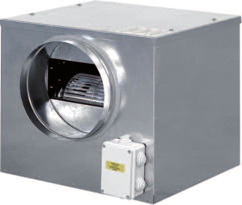
CSS CSS/E CRS serie/series

CSS CSS/E CASSONETTI VENTILANTI SILENZIATI                        CSS CSS/E NOISELESS VENTILATING BOXES

INDICE                                                            CONTENTS

1 CARATTERISTICHE TECNICHE                                        1 TECHNICAL SPECIFICATIONS
1.1 Caratteristiche generali                              4       1.1 General characteristics                            4
1.2 Dimensioni e pesi                                     4       1.2 Dimensions and weights                             4
1.3 Caratteristiche elettriche                            5       1.3 Electrical specifications                          5

2 CURVE CARATTERISTICHE                                   6       2 CHARACTERISTICS CURVES                                6
2.1 Curve aerauliche unità CSS                            6       2.1 CSS units aeraulic curves CSS                       6
2.2 Curve aerauliche unità CSS/E                          7       2.2 CSS/E units aeraulic curves CSS/E                   7

3 ACCESSORI                                                       3 ACCESSORIES
3.1 Accessori                                            8        3.1 Accessories                                         8
3.2 Regolatore di velocità VVM                           8        3.2 Speed controller VVM                                8
3.3 Commutatore stella – triangolo CTS 12                8        3.3 Delta – star switch CTS 12                          8
3.4 Regolatore potenziometrico di velocità - PVR         9        3.4 Potentiometric speed controller - PVR               9
3.5 Sensore di pressione differenziale - PSC             9        3.5 Differential air pressure sensor - PSC              9

CRS CASSONETTI VENTILANTI RIBASSATI                               CRS LOW BODY VENTILATING BOXES

INDICE                                                            CONTENTS

1 CARATTERISTICHE TECNICHE                                        1 TECHNICAL SPECIFICATIONS
1.1 Caratteristiche generali                             11       1.1 General characteristics                            11
1.2 Dati tecnici unità                                   11       1.2 Unit technical specifications                      11
1.3 Dimensioni e pesi unità                              11       1.3 Unit dimensions and weights                        11

2 CURVE CARATTERISTICHE                                  12       2 CHARACTERISTICS CURVES                               12

3 ACCESSORI                                                       3 ACCESSORIES
3.1 Accessori                                            13       3.1 Accessories                                        13
3.2 Disposizione accessori per unità serie CRS           13       3.2 Position of accessories for the CRS series units   13
3.3 Sezione filtrante FA                                 13       3.3 Filtering section FA                               13
3.4 Sezione di post-riscaldamento ad acqua SBC           14       3.4 Water post-heating section SBC                     14
3.5 Sezione di post-riscaldamento elettrico SBE o SB2E   15       3.5 Electric post-heating section SBE or SB2E          15
3.6 Plenum di mandata SPM                                16       3.6 Outlet plenum SPM                                  16
3.7 Plenum per condotti flessibili SPF                   17       3.7 Plenum for flexible ducts SPF                      17
3.8 Flangia di mandata FL                                17       3.8 Outlet flange FL                                   17
3.9 Bocchetta ad alette regolabili BMO                   17       3.9 Outlet with adjustable fins BMO                    17
3.10 Controllo velocità C3V                              17       3.10 Speed controller C3V                              17
3.11 Pannello di controllo unità PCM                     18       3.11 Unit control panel PCM                            18
3.12 Pannello di controllo unità + post-riscaldamento    18       3.12 Unit control panel + electric post-heating        18
     elettrico PCMR                                                    section PCMR

                                                              2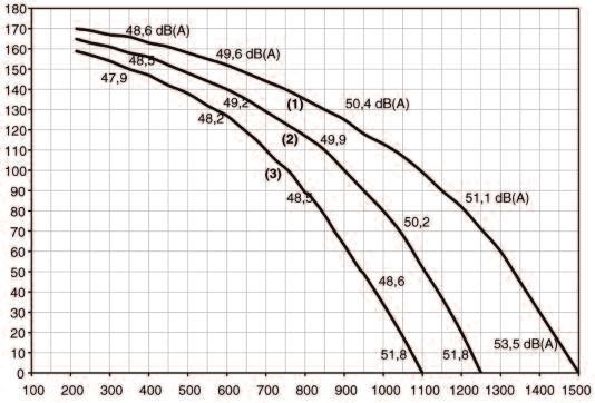
CSS CSS/E serie/series

          CASSONETTI VENTILANTI SILENZIATI                                                   NOISELESS VENTILATING BOXES

INTRODUZIONE                                                                     INTRODUCTION
Le unità di estrazione della serie CSS sono composte da cassonetti               The CSS extraction units are ventilating chambers with suitable
ventilanti opportunamente insonorizzati al fine di ottenere una estrema          soundproofing to ensure extremely silent operation.
silenziosità di funzionamento.                                                   The series is made up of eight models, with directly coupled fans with
La serie è composta da otto modelli con ventilatori direttamente                 double inlet type with statically- and dynamically-balanced impellers to
accoppiati a doppia aspirazione, le giranti sono bilanciate staticamente e       minimise vibrations and noise (CSS), and five models fitted with EC
dinamicamente per ridurre al minimo le vibrazioni e il rumore (CSS) e da         technology motors for a lower power consumption and higher air
5 modelli dotati di motori a tecnologia EC in grado di assicurare bassi          performance compared to standard fan motors (CSS/E).
consumi di energia e di garantire al contempo prestazioni aerauliche             The high working static pressures allow the use of ducting for the
nettamente superiori agli equivalenti standard (CSS/E).                          extraction or distribution of air in a series of rooms.
Le elevate pressioni statiche disponibili, permettono il montaggio di            With different combinations of rotor diameter, speed and power supply,
canali consentendo l’estrazione o l’immissione dell’aria su più ambienti.        the range covers a field of flow-rates from 200 to 6,500 m3/h, with static
Con diverse combinazioni di diametro girante, velocità di rotazione e            pressures up to 800 Pa.
alimentazione, la gamma copre un campo di portate da 200 a 6.500 m3/h
con pressioni statiche fino a 800 Pa.

CSS:                                                                                                                  CSS:
•  ventilatori direttamente accoppiati                                                                                •  directly coupled fans
•  estrema silenziosità                                                                                               •  extremely silent

CSS/E:                                                                                                                CSS/E:
•   ventilatori EC                                                                                                    •   fan EC
•   elevate prestazioni                                                                                               •   higher performance
•   bassi consumi                                                                                                     •   lower power consumption

                                                                             3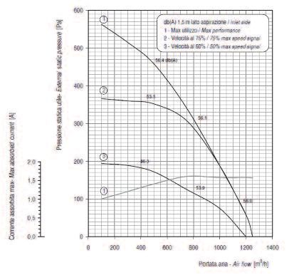
CSS CSS/E serie/series

1 CARATTERISTICHE TECNICHE                                                          1 TECHNICAL SPECIFICATIONS
1.1 CARATTERISTICHE COSTRUTTIVE                                                     1.1 CONSTRUCTIVE CHARACTERISTICS
• La struttura è realizzata in lamiera zincata con contropannellatura               • The structure is made from galvanised plate with perforated internal
  interna forata.                                                                     panelling.
• L’isolamento acustico interposto nell’intercapedine è garantito da uno            • A 50 mm-thick layer of soundproofing material (glass wool) is positioned
  spessore di 50 mm di materiale fonoisolante (lana di vetro).                        between the plate and the panelling to ensure sound insulation.
• La serie CSS monta elettroventilatori centrifughi a doppia aspirazione            • The CSS series units are fitted with double inlet centrifugal fans, with
  con girante a pale avanti con elevate pressioni statiche disponibili.               forward-blade impellers and high working static pressures.
• Tutte le giranti dei ventilatori sono bilanciate dinamicamente e                  • All the fan impellers are dynamically- and statically-balanced to
  staticamente per ridurre al minimo le vibrazioni e il rumore. I motori sono         minimise vibrations and noise. The directly coupled motors feature
  del tipo a rotore esterno direttamente accoppiato. Il modello CSS-T 450             external rotors. The model CSS-T 450 has a built-in overload contact.
  ha incorporato un contatto termico per la protezione dello stesso.                • The CSS/E series units are fitted with double inlet forward curved
• La serie CSS/E monta elettroventilatori di tipo centrifugo a doppia                 direct driven fans fitted with EC motors; control & power driver wired
  aspirazione direttamente accoppiati a motori elettrici EC; driver di                to the motor and mounted externally inside a metal box
  controllo cablato al motore e montato esternamente dentro involucro               • Vibration-damping mounts are installed between the structure and the
  metallico.                                                                          fan, to attenuate the transmission of any vibrations
• Per attenuare la trasmissione di eventuali vibrazioni fra struttura e             • The operating temperature must be between –20°C and +40°C.
  ventilatore sono interposti degli antivibranti                                    • The fans are inspected and removed from above.
• La temperatura di esercizio deve essere compresa fra i –20°C e i +40°C.
• L’eventuale ispezione ed estrazione del ventilatore avviene dall’alto.

1.2 DIMENSIONI E PESI UNITÀ                                                         1.2 DIMENSIONS AND WEIGHTS

     Modello / Model                                       Dimensioni / Dimensions                                   Peso / Weight (kg) Peso / Weight (kg)
                                    A                B               C                   D                E                 CSS               CSS/E
        CSS 160                    400              400            300                  160              200                 15
        CSS 200                    400              450            400                  200              250                 22
    CSS 250 e CSS/E                400              450            400                  250              250                 22                   24
    CSS 315 e CSS/E                550              550            550                  315              300                 42                   44
    CSS 355 e CSS/E                550              550            550                  355              300                 45                   48
    CSS 400 e CSS/E                650              650            650                  400              380                 65                   68
  CSS 450/450T e CSS/E             750              750            750                  450              430                 83                   87

                                                                                4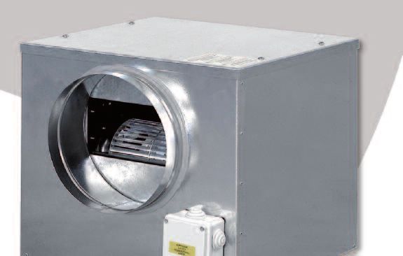
CSS CSS/E serie/series

1.3 CARATTERISTICHE ELETTRICHE                                                                                  1.3 ELECTRICAL SPECIFICATIONS
    Modello         Potenza    Corrente max N° velocità  Poli Grado di protezione Classe isolamento Alimentazione elettrica Pressione sonora max (2)
     Model         Power input Max current Speed number Poles Enclosure protection Insulation class    Electrical supply    Max sound pressure level (2)
                          W                   A                   N°              N°                 IP                                                 V / Ph / Hz                              dB (A)
   CSS 160              88 (1)              0.40                   1               2                 44                          F                      230 / 1 / 50                               40
   CSS 200               90                 0.75                   1               2                 44                          F                      230 / 1 / 50                               40
   CSS 250               90                 1.18                   1               2                 44                          F                      230 / 1 / 50                               48
   CSS 315               147                1.50                   1               4                 55                          F                      230 / 1 / 50                               48
   CSS 355               420                3.60                   1               4                 55                          F                      230 / 1 / 50                               52
   CSS 400               550                4.60                   1               4                 55                          F                      230 / 1 / 50                               62
   CSS 450               736                6.80                   1               6                 55                          F                      230 / 1 / 50                               50
                                            7.40                                                                                                        230 / 3 / 50
   CSS 450T             1100                                       1               6                 44                          F                                                                 65
                                            4.30                                                                                                        400 / 3 / 50

(1) La potenza indicata è la potenza assorbita dalla rete elettrica e non quella disponibile al ventilatore.
    The shown power input is the absorbed one, not that available at the fan.
(2) Livello di pressione sonora: valori riferiti a 1,5 metri dall’aspirazione della macchina in campo libero.
    Il livello di rumore operativo generalmente si discosta dai valori indicati sui grafici a seconda delle condizioni di funzionamento, del rumore riflesso e del rumore periferico.
    Sound pressure level: data referred to 1,5 meters from inlet in free field.
    The actual operation noise level generally differs from the values shown in the table, depending on the operating conditions, on the reflected noise and on the surrounding noise.

                                   Max potenza assorbita (1)                Max assorbimento (1)                                                   Classe di isolamento                  Alimentazione elettrica
       MODELLO                        Max power input                           Max current                  Segnale di controllo (2)                Insulation class                        Power supply
        MODEL                                W                                       A                         Fan speed control                            IP                                V / Ph / Hz
      CSS/E 250                                370                                     1,6                         0-10V / PWM                               32                            230 / 1 / 50(60)
      CSS/E 315                                750                                     3,2                         0-10V / PWM                               54                            230 / 1 / 50(60)
      CSS/E 355                               1200                                     5,1                         0-10V / PWM                               54                            230 / 1 / 50(60)
      CSS/E 400                               1150                                     4,8                         0-10V / PWM                               54                            230 / 1 / 50(60)
      CSS/E 450                               1750                                     7,4                         0-10V / PWM                               54                            230 / 1 / 50(60)

1) “Max potenza assorbita” e “Max assorbimento” si riferiscono alla velocità del                               1) “Max power input” and “Max current” are related to fan speed corresponding to max
   ventilatore corrispondente al max segnale di controllo                                                          fan speed control signal
2) Ad eccezione di CSS/E 250, possibilità di gestione del ventilatore anche attraverso                         2) Fan speed control by MODBUS also (CSS/E 250 excluded)
   seriale MODBUS

                                                                                                      5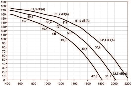
CSS CSS/E serie/series
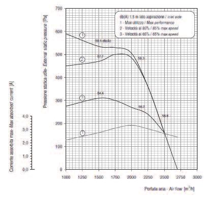
2 CURVE CARATTERISTICHE 2 CHARACTERISTICS CURVES
2.1 CURVE AERAULICHE UNITÀ CSS 2.1 CSS UNITS AERAULIC CURVES
CSS 160 CSS 200
450 450
Pressione statica / Static pressure (Pa)
400 400
Pressione statica / Static pressure (Pa)
350 350
300 300
250 250
200 200
150 150
100 100
50 50
0 0
0 100 200 300 400 0 100 200 300 400 500 600 700 800
Portata aria / Air flow (m3/h) Portata aria / Air flow (m3/h)
CSS 250 CSS 315
500
300
450
400
Pressione statica / Static pressure (Pa)
Pressione statica / Static pressure (Pa)
250
350
300 200
250
150
200
150 100
100
50 50
0
0 100 200 300 400 500 600 700 800 900 1000 0
0 500 1000 1500 2000
Portata aria / Air flow (m3/h) Portata aria / Air flow (m3/h)
CSS 355 CSS 400
450 600
400
Pressione statica / Static pressure (Pa)
Pressione statica / Static pressure (Pa)
500
350
300 400
250
300
200
150 200
100
100
50
0 0
0 500 1000 1500 2000 2500 3000 0 500 1000 1500 2000 2500 3000 3500
Portata aria / Air flow (m3/h) Portata aria / Air flow (m3/h)
CSS 450 CSS 450 T
450 450
400 400
Pressione statica / Static pressure (Pa)
Pressione statica / Static pressure (Pa)
350 350
300 300
250 250
200 200
150 150
100 100
50 50
0 0
0 1000 2000 3000 4000 5000 6000 0 1000 2000 3000 4000 5000 6000 7000 8000
Portata aria / Air flow (m3/h) Portata aria / Air flow (m3/h)
6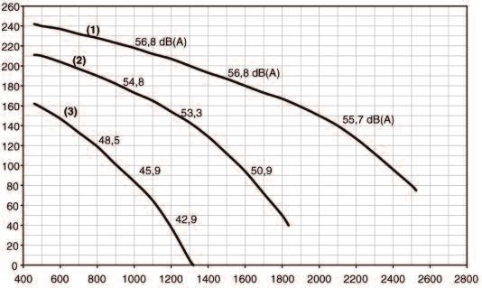
CSS CSS/E serie/series

2.2 CURVE AERAULICHE UNITÀ CSS/E       2.2 CSS/E UNITS AERAULIC CURVES

   CSS/E 250                               CSS/E 315

    CSS/E 355                              CSS/E 400

   CSS/E 450

                                   7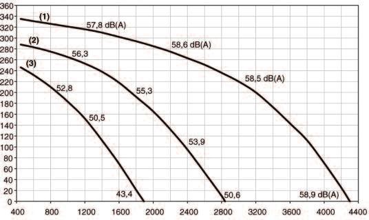
CSS CSS/E serie/series

3 ACCESSORI                                                                                         3 ACCESSORIES

3.1 ACCESSORI                                                                                       3.1 ACCESSORIES
- Regolatori elettronici monofase VVM                                                               - Single-phase electronic controller VVM
- Autotrasformatore trifase VVT                                                                     - Three-phase autotransformer VVT
- Commutatore stella-triangolo CST 12*                                                              - Delta-star switch CST 12*
- Regolatore potenziometrico di velocità - PVR**                                                    - Potentiometric speed controller - PVR**
- Sensore di pressione differenziale - PSC**                                                        - Differential air pressure sensor - PSC**

(*) disponibile solo per CSS mod. 450T (**) disponibile solo per serie CSS/E                        (*) available for CSS mod. 450T (**) available of CSS/E series only

3.2 REGOLATORE DI VELOCITÀ VVM                                                                      3.2 SPEED CONTROLLER VVM
Il regolatore di velocità VVM è adatto per l’installazione a parete e                               The VVM speed controller is suitable for wall mounting and is used to
permette la regolazione del ventilatore con motore monofase.                                        control the fans with single-phase motors. There are four types of
Esistono quattro modelli di regolatore a seconda della corrente assorbita                           controller, chosen according to the current input of the fan motor:
dal motore del ventilatore:
                  VVM 1,5 - VVM 3 - VVM 5 - VVM 7,5                                                                       VVM 1.5 - VVM 3 - VVM 5 - VVM 7,5

Sul frontalino del comando sono presenti:                                                           The front panel features:
- interruttore on–off                                                                               - an on–off switch
- manopola regolazione continua della velocità.                                                     - a continuous speed control knob.

Caratteristiche tecniche                                                                            Technical specifications
   Modelli      Alimentazione          Corrente Nominale    Corrente Massima   Campo di regolazione        Valida per CSS
   Model       Electrical supply        Nominal current     Maximum current      Regulation range           Valid for CSS
   VVM 1,5        230 / 1 / 50               1,5 A                3A             40% a 100% Vmax            160-200-250
   VVM 3          230 / 1 / 50                3A                  5A             40% a 100% Vmax                315
    VVM 5         230 / 1 / 50                5A                 7,5 A           40% a 100% Vmax              355-400
   VVM 7,5        230 / 1 / 50               7,5 A               12 A            40% a 100% Vmax                450

3.3 COMMUTATORE STELLA - TRIANGOLO CST 12                                                           3.3 DELTA - STAR SWITCH CST 12

Il commutatore CSS permette la commutazione stella - triangolo dei                                  The CSS switch is used as accessorie for the three-phase model CSS
motori motori trifase utilizzati per il modello CSS 450T.                                           450T and allows the delta-star switching of the motors.

Sul pannello frontale è presente un selettore a tre posizioni:                                      The front panel features a three-position switch:
- Off / Funzionamento a stella / Funzionamento a triangolo.                                         - Off / Star operation / Delta operation.

   Modello         Alimentazione            Corrente Nominale        Regolazione commutatore             Valida per CSS
    Model         Electrical supply          Nominal current               Setting knob                   Valid for CSS
                                                                         Off/Stella/Triangolo -
   CST 12         400 / 3 / 50-60 Hz                 12 A                                                     450 T
                                                                  Off/Star operation/Delta operation

                                                                                                8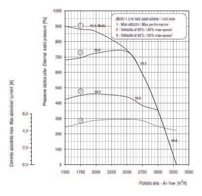
CSS CSS/E serie/series

3.4 REGOLATORE POTENZIOMETRICO DI VELOCITÀ - PVR                                          3.4 POTENTIOMETRIC SPEED CONTROLLER - PVR
E’ un potenziometro rotante per installazione a bordo macchina o a                        It’s a rotating potentiometer for on-board or electrical box installation,
quadro, idoneo esclusivamente all’attivazione dei ventilatori ed al                       suitable just for switching on/off the fans and for manual fan speed
controllo manuale della loro velocità.                                                    controlling.
Caratteristiche tecniche                                                                  Technical characteristics

 V+               +5V / +10V input
                  (proveniente da un solo ventilatore / coming from one fan)

 V-               GND (comune / common)

 V1               0-5V / 0-10V (segnale ventilatore 1 / output signal fan 1)

 V2               0-5V / 0-10V (segnale ventilatore 2 / output signal fan 2)

 Protezione:      IP 20
 Protection:
segnale 0-5V compatibile con +5V               0-5V signal compatible with +5V input
segnale 0-10V compatibile con +10V             0-10V signal compatible with +10V input

3.5 SENSORE DI PRESSIONE DIFFERENZIALE - PSC                                              3.5 DIFFERENTIAL AIR PRESSURE SENSOR - PSC
Idoneo al controllo automatico della ventilazione in modalità “a                          Suitable for automatic fan speed control on “constant pressure” (or
pressione costante” (o “a portata costante”), è già integrato di logica di                “constant flow”) mode, it’s already provided with PID control logic and
regolazione PID con uscita 0-10 V. Il set di regolazione viene impostato                  supplies 0-10V output. Pressure setpoint is set and read on the sensor
e letto a display sul sensore, il quale pilota direttamente il driver di                  display, which directly controls the driver of each fan wihout any other
ciascun ventilatore senza necessità di interporre altro regolatore.                       controller.

Caratteristiche tecniche                                                                  Technical characteristics

 Alimentazione:
                           230 Vac (+/-10%); 50Hz
 Power supply:
                           Controllo della pressione differenziale con uscita 0-10V
 Funzione:
 Service:
                           Differential air pressure control with 0-10V output
 Scala massima:
                           500 Pa
 Full scale:
 Grado di protezione:
                           IP 65
 Enclosure protection:
 Temp. di funzionamento:
                           -10°C ... +50°C
 Operating temperature:

                                                                                      9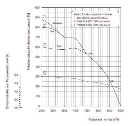
CRS serie/series

          CASSONETTI VENTILANTI RIBASSATI                                                         LOW BODY VENTILATING BOXES

INTRODUZIONE                                                                          INTRODUCTION
Le unità di estrazione/immissione aria della serie CRS, a sviluppo                    The CRS series horizontal air extraction/distribution units feature
orizzontale, sono caratterizzate da ridotte dimensioni e facilità di                  compact dimensions and easy assembly.
montaggio. Esse possono essere installate a controsoffitto in                         They can be installed in false-ceilings for residential and commercial
applicazioni di tipo residenziale e commerciale.                                      applications.
La serie CRS è composta da 5 modelli che coprono un campo di portate                  The CRS series is made up of 5 models that cover a range of flow-rates
da 900 a 4300 m3/h. Gli elettroventilatori utilizzati sono del tipo centrifugo        from 900 to 4,300 m3/h.
a tre velocità con giranti bilanciate staticamente e dinamicamente per                Three-speed centrifugal fans are used, with statically- and dynamically-
ridurre al minimo le vibrazioni e il rumore.                                          balanced impellers to minimise vibrations and noise.
Le elevate pressioni statiche disponibili permettono il montaggio di canali           The high working static pressures allow the use of ducting for the
consentendo l’estrazione o l’immissione dell’aria su più ambienti.                    extraction or distribution of air in a series of rooms.

  CRS:                                                                                                                          CRS:
  •  ventilatori centrifughi                                                                                                    •  centrifugal fans
  •  dimensioni ridotte                                                                                                         •  compact dimensions

                                                                                 10
CRS serie/series
1 CARATTERISTICHE TECNICHE 1 TECHNICAL SPECIFICATIONS
1.1 CARATTERISTICHE GENERALI 1.1 GENERAL CHARACTERISTICS
• La struttura è realizzata in Aluzink. • The structure is made from Aluzink.
• L’isolamento acustico e termico interposto nella macchina è garantito • A suitably-thick layer of polyethylene and polyester is installed in the
da un adeguato spessore di polietilene e poliestere. unit to ensure sound and heat insulation.
• I filtri (accessorio) sono facilmente estraibili dal basso allo scopo di • The filters (accessories) are easily removable from below for
permettere la loro periodica pulizia. periodical cleaning.
• Gli elettroventilatori centrifughi con motore a tre velocità hanno giranti • The centrifugal fans with three-speed motors have statically- and
bilanciate sia staticamente che dinamicamente per ridurre al minimo dynamically-balance impellers to minimise vibrations and noise.
le vibrazioni e il rumore. • The operating temperature must be between –20 and 40°C.
• La temperatura di esercizio deve essere compresa fra i –20 e 40°C. • The fan can be inspected or removed from below.
• L’eventuale ispezione o estrazione del ventilatore avviene dal basso. • The unit is fitted with a power board to simplify the electrical
• A bordo macchina è presente una scheda di potenza per facilitare i connections and for the remote control of the fans (this board is not
collegamenti elettrici e il controllo dei ventilatori con eventuali comandi featured on size 09).
remoti (questa scheda non è presente sulla grandezza 09).
1.2 DATI TECNICI UNITÀ 1.2 UNIT TECHNICAL SPECIFICATIONS
Modello / Model CRS 09 15 21 36 43
Portata di aria / Air flow m3/h 900 1550 2200 3650 4300
Pressione sonora / Sound pressure level (*) (D) dB(A) 50 51 55 58 58
Pressione statica disponibile (D) / External static pressure (D) Pa 100 126 135 175 170
Ventilatore / Fan 09 15 21 36 43
Potenza all'asse / Power input W 90 147 184 420 600
Corrente max assorbita / Max absorbed current A 1 1,9 2,6 3,9 5,5
Numero velocità ventilatore / Fan speed number n° 3 3 3 3 3
Poli / Poles n° 4 4 4 4 4
Grado di protezione / Enclosure protection IP 20 20 20 20 20
Classe di isolamento / Insulation class B B B B B
Alimentazione elettrica / Electrical supply V/ph/Hz 230 / 1 / 50
(D) Valutata alla portata nominale / Referred to nominal air flow.
(*) Livello di pressione sonora: valori riferiti a 1,5 m dall’aspirazione della macchina in campo libero. Il livello di rumore operativo si discosta in genere dai valori indicati a seconda delle
condizioni di funzionamento, del rumore riflesso e del rumore periferico / Sound pressure level: data referred to 1,5 m from unit inlet in free field. The actual operation noise level generally differs from
the values shown, depending on the operating conditions, on the reflected noise and on the surrounding noise.
1.3 DIMENSIONI E PESI UNITÀ 1.3 UNIT DIMENSIONS AND WEIGHTS
Modello / Model 09 15 21 36 - 43
A 645 1000 1100 1345
B 296 296 325 375
C 520 520 600 600
D 500 860 960 1200
I 675 1035 1135 1375
L 405 405 435 435
F 210 210 235 260
Peso / Weight (kg) 15 24 30 42
11CRS serie/series
2 CURVE CARATTERISTICHE PORTATA-PREVALENZA 2 FLOW-RATE-STATIC PRESSURE CURVES
CRS 09 CRS 15
Pressione statica / Static pressure (Pa)
Pressione statica / Static pressure (Pa)
Portata aria / Air flow (m3/h) Portata aria / Air flow (m3/h)
CRS 21 CRS 36
Pressione statica / Static pressure (Pa)
Pressione statica / Static pressure (Pa)
Portata aria / Air flow (m3/h) Portata aria / Air flow (m3/h)
CRS 43
Pressione statica / Static pressure (Pa)
Portata aria / Air flow (m3/h)
12CRS serie/series
3 ACCESSORI 3 ACCESSORIES
3.1 ACCESSORI 3.1 ACCESSORIES
- Sezione filtrante FA - Filtering section FA
- Sezione di post-riscaldamento ad acqua SBC - Water post-heating section SBC
- Sezione di post-riscaldamento elettrico SBE o SB2E - Electric post-heating section SBE or SB2E
- Plenum di mandata afonizzato SPM - Sound proofed outlet plenum SPM
- Plenum di mandata per condotti flessibili SPF - Outlet plenum for outlets SPF
- Bocchetta ad alette regolabili BMO - Outlet with adjustable fins BMO
- Flangia di mandata per attacco ai canali FL - Outlet flange for connection to the ducts FL
- Controllo di velocità C3V - Speed controller C3V
- Pannello di controllo unità + sezione di riscaldamento ad acqua PCM - Unit control panel + water heating section PCM
- Pannello di controllo unità + sezione riscaldamento elettrico PCMR - Unit control panel + electric heating section PCMR
3.2 DISPOSIZIONE ACCESSORI PER UNITÀ SERIE CRS 3.2 POSITION OF ACCESSORIES FOR THE CRS SERIES UNITS
C A
3.3 SEZIONE FILTRANTE FA 3.3 FILTERING SECTION FA B
La sezione filtrante è costituita da un filtro rigenerabile classe G3, e si The filtering section is made up of a regenerable class G3 filter, and is
utilizza quando non è possibile prevedere il filtro nella griglia di used when a filter cannot be fitted to the intake grille.
aspirazione. L’estrazione del filtro avviene verso il basso. The filter is removed from below.
Le perdite di carico lato aria sono riportate sul diagramma. The air-side pressure drop values are shown in the table.
Sezione filtrante FA (*) / Filter section FA (*) 09 15 21 36 43
Velocità frontale aria / Face velocity m/s 2,3 2,1 2,4 2,7 3,2
Perdite di carico / Pressure drop Pa 12 10 13 21 27
(*) Dati riferiti alla portata nominale • Data referred to nominal air flow.
CRS
Perdita di carico / Pressure drop
CRS
CRS
CRS
Portata aria / Air flow (m3/h)
3.3.1 Dimensioni e pesi 3.3.1 Dimensions and weights
FA per Modelli / FA forModels 09 15 21 36-43
A 210 210 235 260
B 500 860 960 1200
Peso / Weight (kg) 0,8 1 1,2 1,7
13CRS serie/series
3.3.2 Estrazione filtro 3.3.2 Removing the filter
Per estrarre il filtro svitare le viti di fissaggio come indicato in figura To remove the filter, unscrew the fastening screw as shown in the figure
3.4 SEZIONE DI POST-RISCALDAMENTO AD ACQUA SBC 3.4 WATER POST-HEATING SECTION SBC
L’utilizzo della sezione SBC avviene quando si necessiti prevedere un The SBC section is used when post–heating is required on the base unit.
post – riscaldamento sull’unità base. La sezione SBC contiene una The SBC section contains a two-row water coil, with manifolds that
batteria ad acqua a 2 ranghi con collettori che sporgono lateralmente protrude from the side of the section.
rispetto alla sezione.
Sezione post-Riscaldamento SBC / Post-heating section SBC (**) 09 15 21 36 43
Potenza termica / Heating capacity W 6800 10900 13500 20300 22200
Perdita di carico lato acqua / Water pressure drop kPa 10 11 15 20 24
Portata acqua / Water flow rate m3/h 0,58 0,96 1,34 2,13 2,33
Perdita di carico lato aria / Air pressure drop Pa 22 18 24 34 44
(**) Temperatura aria ingresso 20 °C BS. Temperatura acqua ingresso/uscita 70/60 °C. Portata aria nominale.
Inlet air temperature 20 °C BS. In/out water temperature 70/60 °C. Nominal air flow.
3.4.1 Dimensioni e pesi 3.4.1 Dimensions and weights
Modello / Model 09 15 21 36 - 43
A 615 975 1075 1315
B 296 296 325 375
D 83 83 133 118
E 440 800 800 1070
F 91 91 141 126
G 3/4” 3/4” 3/4” 3/4”
Peso / Weight (kg) 6,0 9,0 11,0 16,5
3.4.2 Rese termiche 3.4.2 Heating performance
Grandezza Temp. ingresso/uscita acqua Temperatura aria ingresso °C / Inlet air temperature °C
Size Inlet/oulet water temperature °C 10 kWt 16 kWt 19 kWt 20 kWt 21 kWt
80/70 9,9 9 8,6 8,4 8,3
SBC 09
70/60 8,3 7,4 6,95 6,8 6,7
80/70 15,7 14,4 13,7 13,4 13,2
SBC 15
70/60 13,3 11,8 11,1 10,9 10,6
80/70 19,7 17,9 17 16,7 16,5
SBC 21
70/60 16,5 14,7 13,8 13,5 13,2
80/70 29,6 27 25,7 25,2 24,8
SBC 36
70/60 24,8 22,2 20,8 20,3 19,9
80/70 32,3 29,5 28 27,5 27
SBC 43
70/60 27,1 24,2 22,7 22,2 21,7
kWt = Potenza Termica Totale Valori riferiti alla portata d’aria nominale. / kWt = Heating capacity. Data referred to nominal air flow.
14CRS serie/series
3.4.3 Perdite di carico lato aria sezione SBC 3.4.3 Air-side pressure drop, SBC section
CRS
CRS
Perdita di carico / Pressure drop CRS
CRS
Portata aria / Air flow (m3/h)
3.4.4 Perdite di carico lato acqua sezione SBC 3.4.4 Water-side pressure drop, SBC section
Nota la potenza resa (kW) e il salto termico (DT) fra l’ingresso e l’uscita For a given output (kW) and thermal head (DT) between the water inlet
dell’acqua nella batteria, dal diagramma 1 si deduce la portata d’acqua. and outlet on the coil, diagram 1 shows the water flow-rate. Use this flow-
Introducendo questa portata nel diagramma 2 si possono ricavare le rate in diagram 2 to calculate the pressure drop.
perdite di carico.
Diag. 1
Diag. 2
Prerdita di carico / Pressure drop (kPa)
Portata acqua / Water flow (m3/h)
CRS
CRS
CRS
CRS
Portata acqua / Water flow (m3/h)
Potenza / Capacity (kW)
3.5 SEZIONE DI POST-RISCALDAMENTO ELETTRICO SBE O SB2E 3.5 ELECTRIC POST-HEATING SECTION SBE OR SB2E
L’utilizzo della sezione SBE è consigliato quando si necessiti prevedere The use of the SBE section is recommended when post-heating is
un post - riscaldamento e non sia disponibile l’acqua. La sezione SBE required and water is not available. The SBE section contains a filament-
contiene una resistenza di tipo a filamento, per contenere le perdite di type heating element, which limits pressure drop.
carico. La sezione SBE con resistenza elettrica richiede linea trifase 400 / The SBE section with electric heater requires a three-phase, 400 / 3 / 50
3 / 50 può essere controllata dal pannello di comando PCMR ed è power supply, is managed using the PCMR control panel and comes
completa di termostati di sicurezza e di relè di comando, mentre la complete with safety thermostats and control relay, while the line
protezione della linea deve essere eseguita a cura dell’installatore. protection devices must be fitted by the installer.
Sez. post-riscaldamento elettrico SBE / Electrical post-heating sec. SBE 09 15 21 36 43
Resa resistenza elettrica ad 1 elemento / Heating capacity 1 element kW 3 4,5 4,5 6 6
Corrente assorbita / Absorbed current A 4,3 6,5 6,5 8,6 8,6
Alimentazione elettrica / Power supply V / ph / Hz 400 / 3 / 50
Perdite di carico ( ‘ ) / Pressure drop Pa 5 4 6 9 14
Sezione post-riscaldamento elettrico SB2E / Electrical post-heating sec. SB2E 09 15 21 36 43
Resa resistenza elettrica a 2 elementi / Heating capacity 2 elements kW 6 9 9 12 12
Corrente assorbita / Absorbed current A 8,6 13,0 13,0 17,2 17,2
Alimentazione elettrica / Power supply V / ph / Hz 400 / 3 / 50
Perdite di carico ( ‘ ) / Pressure drop Pa 10 8 12 18 28
( ‘ ) Dati riferiti alla portata nominale / Data referred to the nominal air flow.
15CRS serie/series
3.5.1 Dimensioni e pesi 3.5.1 Dimensions and weights
Modello / Model 09 15 21 36 - 43
A 615 975 1075 1315
B 296 296 325 375
D 83 83 133 118
B
E 440 800 800 1070
F 91 91 141 126
Peso / Weight (kg) 5.5 7.5 8.5 11.0
3.5.2 Perdite di carico lato aria sezione SBE 3.5.2 Air-side pressure drop, SBE section
CRS
Perdita di carico / Pressure drop
CRS
CRS
CRS
Portata aria / Air flow (m3/h)
3.6 PLENUM DI MANDATA SPM 3.6 OUTLET PLENUM SPM
Il plenum di mandata SPM è fornito in tutti quei casi dove si ha la The SPM outlet plenum is supplied in cases where uniform air distribution
necessità di uniformare la distribuzione dell’aria. is required.
3.6.1 Dimensioni e pesi 3.6.1 Dimensions and weights
Modello / Model 09 15 21 36 - 43
A 615 975 1075 1315
B 296 296 325 375
D 83 83 133 118
E 440 800 800 1070
F 91 91 141 126
Peso / Weight (kg) 4.1 5.3 6.4 9.1
16CRS serie/series
3.7 PLENUM PER CONDOTTI FLESSIBILI SPF 3.7 PLENUM FOR FLEXIBLE DUCTS SPF
Il plenum di mandata SPF consente un collegamento rapido delle unità e The SPF outlet plenum allows the quick connection of the unit and the
dei condotti flessibili per la distribuzione dell’aria in ambiente. flexible ducts for the distribution of air into the room.
La struttura della sezione SPF è realizzata in Aluzink con anelli circolari The structure of the SPF section is made from Aluzink, with suitably-
di diametro d=200 mm. sized circular rings, diameter 200 mm.
3.7.1 Dimensioni e pesi 3.7.1 Dimensions and weights
Modello / Model 09 15 21 36 - 43
A 615 975 1075 1315
B 296 296 325 375
N° boc. / Connection N° 2 3 3 4
Peso / Weight (kg) 4.9 7.1 7.9 10.8
3.8 FLANGIA DI MANDATA FL 3.8 OUTLET FLANGE FL
La flangia di mandata FL facilita il collegamento dell’unità alle The FL outlet flange simplifies the connection of the unit to the ducting.
canalizzazioni.
3.8.1 Dimensioni e pesi 3.8.1 Dimensions and weights
Modello / Model 09 15 21 36 - 43
A 615 975 1075 1315
A1 440 800 800 1070
B 296 296 325 375
B1 235 235 235 280
Peso / Weight (kg) 1.5 2.5 2.8 3.5
3.9 BOCCHETTA AD ALETTE REGOLABILI BMO 3.9 OUTLET WITH ADJUSTABLE FINS BMO
La bocchetta BMO viene utilizzata come accessorio terminale di un The BMO outlet is used as the terminal accessory for the system. The
impianto. La bocchetta va installata sul plenum SPM oppure sulla outlet should be installed on the SPM plenum or alternatively on the SBE
sezione di post-riscaldamento SBE - SBC. or SBC post-heating section.
La bocchetta BMO permette una ottima distribuzione dell’aria in The BMO outlet allows excellent air distribution into the room, thanks to
ambiente grazie al doppio ordine di alette regolabili. the double row of adjustable fins.
3.9.1 Dimensioni e pesi 3.9.1 Dimensions and weights
Modello / Model 09 15 - 21 36 - 43
A 440 800 1070
B 235 235 280
Peso / Weight (kg) 1.2 2 2.5
3.10 CONTROLLO VELOCITÀ C3V 3.10 SPEED CONTROLLER C3V
Adatto per l’installazione a parete, consente di commutare le tre velocità Suitable for wall mounting, it is used to select the three speeds for the
dell’elettro-ventilatore. electric fan.
Il C3V presenta i seguenti comandi: The C3V features the following controls:
- Interruttore on/off; - On/off switch;
- commutatore a tre posizioni delle velocità (minima, media, massima) - three-position speed switch ( minimum, medium, maximum)
- alimentazione 230 V. - 230V power supply.
17CRS serie/series
Caratteristiche tecniche Technical characteristics
Alimentazione:
Power supply: 230 +/- 10% Va.c; 50/60Hz
Regolazioni: Commutatore manuale: On / Off
Commutatore tre velocità: Min / Med / Max
Adjustments: On / Off manual switch
3 - speed switch: Min / Med / Max
Max carico collegabile:
Max load: 2A a/at 250 V a.c
Grado di protezione:
Enclosure protection: IP 30
Temperatura di funzionamento:
Operating temperature: 0°C -40°C
3.11 PANNELLO DI CONTROLLO UNITÀ PCM 3.11 UNIT CONTROL PANEL PCM
Il pannello PCM, per installazione a parete, consente il controllo della The PCM panel is suitable for wall mounting, and is used to control the
temperatura ambiente inverno/estate, dà il consenso per l’attivazione o room temperature in both heating and cooling operation, to enable or
l’esclusione della batteria ad acqua e seleziona la velocità di lavoro del disable the electric coil, and to select the fan operating speed (minimum,
ventilatore (minima, media, massima). medium, maximum).
Sul pannello di comando sono presenti: The PCM features the following controls:
- selettore “Estate / Off / Inverno ”; - manual switch “Summer / Off / Winter ”;
- selettore “Velocità” (minima, media, massima); - three-position speed switch (minimum, medium, maximum).
- manopola regolazione della temperatura; - temperature control knob;
Alimentazione: 230 V 230V power supply
Caratteristiche tecniche Technical characteristics
Alimentazione:
230 V ac -15 / +10% Vac; 50/60Hz
Power supply:
Potenza assorbita:
3 VA
Absorbed power
Relè intervento:
Interrupting relay 5A a/at 250 V ac
Regolazioni: Manopola termostato ambiente
Commutatore manuale: Estate / Off / Inverno
Commutatore tre velocità: Min / Med / Max
Settings: Environment thermostat knob
Manual switch: Summer / Off / Winter
3-speed switch: Min / Med / Max
Temperatura di funzionamento:
Operating temperature: 0°C -40°C
Campo di regolazione:
10°C -30°C
Adjustment range:
Grado di protezione:
Enclosure protection: IP 20
3.12 PANNELLO DI CONTROLLO UNITÀ + SEZIONE POST-RISCAL- 3.12 BASE UNIT + ELECTRIC POST-HEATING SECTION CONTROL
DAMENTO ELETTRICO PCMR PANEL PCMR
Il pannello PCMR per installazione a parete, consente il controllo della The PCMR panel is suitable for wall mounting, and is used to control the
temperatura ambiente inverno/estate, dà il consenso per l’attivazione o room temperature in both heating and cooling operation, to enable or
l’esclusione della resistenza elettrica e seleziona la velocità di lavoro del disable the electric heater, and to select the fan operating speed
ventilatore (minima, media, massima). (minimum, medium, maximum).
Sul pannello di comando sono presenti: The control panel features:
- pulsante on-off ; - on-off button ;
- pulsante velocità ; - speed button ;
- pulsante menù ; - menù button ;
- manopola regolazione della temperatura; - temperature control knob;
- display LCD per la visualizzazione della temperatura e delle impostazioni - 3-digits LCD display to show temperatures and settings.
Alimentazione 230 V 230 V power supply
Caratteristiche tecniche Technical characteristics
Alimentazione:
230 V ac +/-10% Vac; 50/60Hz
Power supply:
Potenza assorbita:
1,2 W
Absorbed power:
Portata contatti: Ventilatori / Fans: 3 A a/at 230 V ~ cos ø=1
Contact rating: Resistenza / Electric heater : 1 A a/at 230 V ~ cos ø=1
Temperatura di funzionamento:
Operating temperature: 0°C -50°C
Campo di regolazione:
5°C -35°C
Adjustment range:
Grado di protezione:
Enclosure protection: IP 20
18CSS CSS/E CRS serie/series
NOTE
19via Leonardo da Vinci, 26 31021 MOGLIANO VENETO (TV) ITALY tel. +39 041 5931151 - +39 041 5931143 fax +39 041 5931158 e-mail: sitalklima@sitalklima.it www.sitalklima.it
Puoi anche leggere