4D POLE 817.500 - IT - KONG - Safety Equipment
←
→
Trascrizione del contenuto della pagina
Se il tuo browser non visualizza correttamente la pagina, ti preghiamo di leggere il contenuto della pagina quaggiù
4D POLE
  817.500

       IT
CERTIFIED BY - CERTIFICATO DA:
NB n° 0123 TÜV SÜD Product Service GmbH
Daimlerstraße 11 - 85748 Garching - Germany
Download the declarance of conformity at:
Scarica la dichiarazione di conformità a :
www.kong.it/conformity
Laden Sie die Übersetzung in Ihrer Sprache herunter
Download the translation in your language
Bájate la traducción en tu idioma
Télécharger la traduction dans vostre langue
Scarica la traduzione nella tua lingua
ZZV05439 rev.01 INFORMAZIONI GENERALI 1.1) Le informazioni fornite dal fabbricante (di seguito informazioni) devono essere lette e ben comprese dall’utilizzatore prima dell’impiego del dispositivo. 1.2) Tutti i nostri dispositivi sono collaudati/controllati pezzo per pezzo in accordo alle proce- dure del Sistema Qualità certificato secondo la norma UNI EN ISO 9001. 1.3) I dispositivi di protezione individuale sono certificati dall’organismo accreditato riportato nelle istruzioni specifiche del dispositivo in accordo all’annesso V del Regolamento (UE) 2016/425. Se di III Categoria sono sottoposti alla sorveglianza di produzione in accordo all’annesso VIII del Regolamento (UE) 2016/425 da parte dall’ente notificato il cui numero di accreditamento è marcato sul dispositivo. 1.4) E’ vivamente consigliato l’uso personale del dispositivo per mantenere continuamente monitorati il grado di protezione e di efficienza. 1.5) Verificare che il dispositivo sia stato fornito integro, nella confezione originale e con le relative informazioni del fabbricante. Per i dispositivi venduti in Paesi diversi dalla destina- zione di origine, il rivenditore ha l’obbligo di verificare e di fornire la traduzione di queste informazioni. 1.6) Questo dispositivo può essere utilizzato in abbinamento ad altri dispositivi quando com- patibili con le informazioni rilevanti del fabbricante. 1.7) Importante 1.7.1) Evitare l’esposizione del dispositivo a fonti di calore e al contatto con sostanze chimi- che. Ridurre al minimo l’esposizione diretta al sole, in particolare per i dispositivi tessili e pla- stici. Temperature basse e presenza di umidità possono facilitare la formazione di ghiaccio, rendere difficile effettuare collegamenti, ridurre la flessibilità, nonché aumentare il rischio di rottura, taglio e abrasione. 1.7.2) La posizione dell’ancoraggio è fondamentale per la sicurezza dell’arresto della cadu- ta: valutare attentamente l’altezza libera presente sotto l’utilizzatore, l’altezza di una poten- ziale caduta, l’allungamento della corda/fune, l’allungamento di un eventuale assorbitore/ dissipatore di energia, la statura dell’utilizzatore e l’effetto “pendolo” in modo da evitare ogni possibile ostacolo (es. il terreno, lo sfregamento, le abrasioni, ecc.). 1.7.3) La resistenza minima dei punti di ancoraggio deve essere di almeno 12 kN, sia realiz- zati su elementi naturali che artificiali. La valutazione di quelli realizzati su elementi naturali (roccia, vegetali, ecc.) è possibile solo in modo empirico, per cui deve essere effettuata da persona formata ed esperta. Per quelli realizzati su elementi artificiali (metallo, calcestruzzo, ecc.), la valutazione è possibile effettuarla scientificamente, pertanto deve essere svolta da persona formata ed autorizzata. www.kong.it versione originale in italiano del 09/01/2019 817.500 4D POLE 3
1.8) Attenzione
    1.8.1) La sospensione prolungata, soprattutto se inerte, può provocare danni irre-
    versibili e anche la morte.
    1.8.2) È assolutamente vietato modificare e/o riparare il dispositivo al di fuori di
    quanto prescritto in queste informazioni.
    1.8.3) Se l’utilizzatore ha il minimo dubbio sull’efficienza del dispositivo lo deve
    sostituire immediatamente, in particolare dopo averlo utilizzato per arrestare una
    caduta.
    1.8.4) Questo dispositivo deve essere utilizzato solo da persone fisicamente ido-
    nee, formate (informate e addestrate) all’uso o sottoposte al controllo diretto di
    formatori/supervisori.
    1.8.5) L’arrampicata su roccia e ghiaccio, le discese, la via ferrata, la speleologia,
    lo sci-alpinismo, il torrentismo, l’esplorazione, il soccorso, l’arborismo e i lavo-
    ri in quota sono tutte attività ad alto rischio che possono comportare incidenti
    anche mortali. L’utilizzatore si assume tutti i rischi derivanti dalla pratica di tali
    attività e dall’uso di ogni nostro dispositivo.
    1.8.6) I test di laboratorio, i collaudi, le informazioni e le norme non sempre riesco-
    no a riprodurre la pratica, per cui i risultati ottenuti nelle reali condizioni d’utilizzo
    del dispositivo possono differire in maniera talvolta anche rilevante. Le migliori
    indicazioni sono fornite dalla continua pratica d’uso sotto la supervisione di per-
    sone competenti/esperte/qualificate.
    1.8.7) Queste informazioni riguardano la descrizione delle caratteristiche, delle
    prestazioni, del montaggio, dello smontaggio, della manutenzione, della con-
    servazione, della disinfezione, ecc. del dispositivo. Anche se contengono alcuni
    suggerimenti di impiego, non devono essere considerate un manuale d’uso nelle
    situazioni reali (cosi come un libretto d’uso e manutenzione di un’autovettura non
    insegna a guidare e non si sostituisce ad una scuola guida).

4                                 versione originale in italiano del 09/01/2019
2 LAVORI IN QUOTA 2.1) Informazioni aggiuntive per i sistemi individuali di protezione contro le cadute dall’alto nell’ambito dei lavori in quota. 2.2) Ai fini della sicurezza in questi sistemi è essenziale: - effettuare la valutazione dei rischi ed accertarsi che l’intero sistema, di cui questo disposi- tivo è solo un componente, sia affidabile e sicuro; - predisporre un piano di soccorso per far fronte ad eventuali emergenze che potrebbero insorgere durante l’utilizzo del dispositivo; - è essenziale posizionare il più in alto possibile il dispositivo di ancoraggio o il punto di ancoraggio; - minimizzare l’altezza di potenziali cadute; - utilizzare dispositivi adatti allo scopo e certificati. 2.3) Importante: in un sistema anticaduta è obbligatorio utilizzare un’imbracatura completa in quanto unico dispositivo utilizzabile per lo scopo, e tale dispositivo deve essere conforme alle norme vigenti. 3 MANUTENZIONE ED IMMAGAZZINAMENTO 3.1) Immagazzinare i dispositivi in un luogo asciutto (umidità relativa 40-90%), fresco (tem- peratura 5-30° C) e buio, chimicamente neutro (evitare assolutamente ambienti salini e/o acidi), lontano da spigoli taglienti, sostanze corrosive o altre possibili condizioni pregiudi- zievoli. 3.2) Trasportare il dispositivo considerando le precauzioni previste per l’immagazzinamento e limitare l’esposizione diretta alla luce del sole e all’umidità. 3.3) Manutenere questo dispositivo come segue: - lavare frequentemente con acqua potabile tiepida (30° C), eventualmente con l’aggiunta di un detergente neutro; - sciacquare e lasciare asciugare, evitando centrifughe e l’esposizione diretta al sole; - solo per i componenti metallici, lubrificare le parti mobili con olio a base di silicone dopo l’asciugatura, evitando il contatto con le parti tessili. 3.4) Se necessario, disinfettare immergendo il dispositivo per un’ora in acqua tiepida con ipoclorito di sodio diluito al 1% (candeggina). Sciacquare accuratamente con acqua potabile, e, senza centrifugare, lasciare asciugare evitando l’esposizione diretta al sole. Evitare la sterilizzazione in autoclave dei dispositivi tessili. www.kong.it versione originale in italiano del 09/01/2019 817.500 4D POLE 5
4 CONTROLLI ED ISPEZIONI
4.1) La sicurezza dell’utilizzatore dipende dalla continua efficienza, integrità e resistenza del
dispositivo, che è necessario monitorare attraverso i controlli e le ispezioni prescritte.
4.2) Prima e dopo l’uso l’utilizzatore deve effettuare tutti i controlli descritti nelle informazioni
specifiche ed in particolare assicurarsi che il dispositivo sia:
- in condizioni ottimali e che funzioni correttamente;
- idoneo all’utilizzo in accordo a queste istruzioni (ogni altro utilizzo è considerato non con-
forme e quindi potenzialmente pericoloso).
4.3) Salvo disposizioni di legge più restrittive, le ispezioni dei dispositivi di III categoria de-
vono essere effettuate:
- almeno ogni 12 mesi a partire dal primo utilizzo;
- l’intervallo di tempo tra le ispezioni può essere ridotto in accordo alla tipologia, alla frequen-
za e all’ambiente di utilizzo;
- da una persona competente (quindi formata e autorizzata dal fabbricante, es. un “Ispettore
DPI KONG”) nel severo rispetto delle indicazioni del fabbricante.
4.4) Gli esiti delle ispezioni periodiche devono essere registrati sulla scheda di ispezione del
dispositivo o su un apposito registro.

5 DURATA DEL DISPOSITIVO
5.1) La durata di vita dei componenti metallici è indeterminabile, teoricamente illimitata,
mentre quelli affetti da invecchiamento riportano la data di scadenza oltre la quale il disposi-
tivo è da sostituire. Questo a condizione che:
- il dispositivo non sia stato utilizzato per arrestare una caduta;
- le modalità di impiego rispettino quanto riportato in queste informazioni;
- l’immagazzinamento e la manutenzione siano effettuati come descritto al punto 3;
- gli esiti di controlli pre-uso e post-uso siano positivi;
- gli esiti delle ispezioni periodiche siano positivi;
- il dispositivo sia utilizzato correttamente non eccedendo il carico marcato di:
            - 1/4 per i dispositivi metallici;
            - 1/10 per i dispositivi tessili.
5.2) Scartare i dispositivi utilizzati per arrestare una caduta o che non hanno superato i con-
trolli pre-uso, post-uso o le ispezioni periodiche.
5.3) L’uso non conforme, le deformazioni, le cadute, l’usura, la contaminazione chimica,
l’esposizione a temperature inferiori a -30°C o superiori a +50°C per i componenti/dispositivi
tessili/plastici e +120°C (es. autoclave) per i dispositivi metallici, sono alcuni esempi di altre
cause che possono ridurre, limitare e terminare la vita del dispositivo.

6                                 versione originale in italiano del 09/01/2019
6 OBBLIGO DI LEGGE 6.1) Le attività professionali e del tempo libero sono sovente regolate da apposite leggi nazionali che possono imporre limiti e/o obblighi all’utilizzo dei DPI e all’approntamento dei sistemi di sicurezza, di cui i DPI sono componenti. 6.2) E’ obbligo dell’utilizzatore conoscere ed applicare tali leggi che potrebbero prevedere limiti differenti da quanto riportato in queste informazioni. 7 GARANZIA 7.1) Il fabbricante garantisce la conformità del dispositivo alle norme vigenti al momento del- la produzione. La garanzia per vizi è limitata ai difetti delle materie prime e di fabbricazione, non comprende la normale usura, l’ossidazione, i danni provocati da uso non conforme e/o in competizioni (in cui non siano specificatamente accettati dagli organizzatori della stessa), da non corretta manutenzione, trasporto, conservazione o immagazzinamento, ecc. La ga- ranzia decade immediatamente nel caso vengano apportate modifiche o manomissioni al dispositivo. 7.2) La validità corrisponde alla garanzia legale del Paese in cui è stato venduto il disposi- tivo, a decorrere dalla data della vendita del prodotto nuovo. Decorso tale termine nessuna pretesa potrà essere avanzata nei confronti del fabbricante. 7.3) Qualsiasi richiesta di riparazione o sostituzione in garanzia dovrà essere accompagnata da una prova di acquisto. Se il difetto è riconosciuto, il fabbricante si impegna a riparare o, a sua discrezione, a sostituire o rimborsare il dispositivo. In nessun caso la responsabilità del fabbricante si estende oltre il prezzo di fattura del dispositivo. www.kong.it versione originale in italiano del 09/01/2019 817.500 4D POLE 7
8 INFORMAZIONI SPECIFICHE
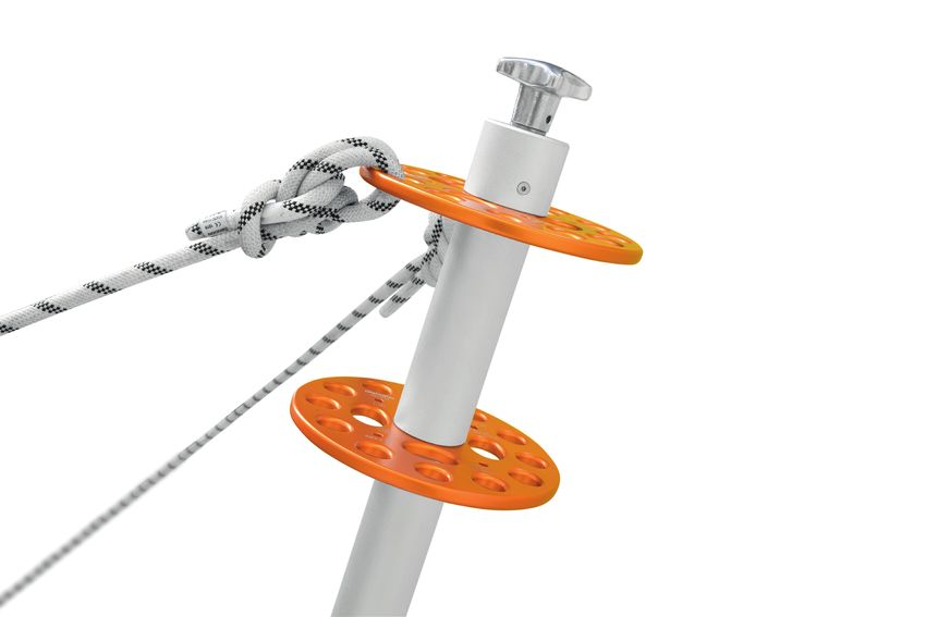
Il dispositivo 817.500 “4D POLE” (fig. 1) è un “monopede” configurabile in diverse modalità.
Può essere utilizzato con una o due piastre 864.018 “DISCORIG” e fino a 5 distanziali (H)
da 15cm l’uno.
CARATTERISTICHE PRINCIPALI
MONO
H
H
130 cm
864.018 DISCORIG
205 cm
H
BIS
8 versione originale in italiano del 09/01/2019Fig. 2 – Nomenclatura delle parti.
NOMENCLATURA
M F
L
D
A
H
C E
B
DISCORIG
864.018
N
L G
(A) Gamba esterna in alluminio – (B) Piede dentato in alluminio e gommato – (C) Golfari
in acciaio – (D) Piastra in alluminio – (E) Gamba interna in alluminio – (F) Sistema di rego-
lazione – (G) Pulsante di sicurezza – (H) Distanziali in alluminio – (L) Foro per la spina di
sicurezza – (M) Spina di sicurezza in acciaio – (N) Giunto cardanico in acciaio con copertura
in gomma.
www.kong.it versione originale in italiano del 09/01/2019 817.500 4D POLE 9Fig. 3 – Configurazione del piede (B) – Il piede (B) può essere montato sia per l’utilizzo su
superfici lisce (asfalto, cemento, etc.) che su superfici discontinue (neve, ghiaia, terra, etc.):
- svitare i golfari (C) e rimuovere le viti;
- allineare la piastra (D) opposta alla superficie a contatto con il terreno;
- riavvitare i golfari (C).
PIEDE MULTIUSO
B
LISCIO
A
SVITARE RIAVVITARE
B D
RUVIDO
C C
TERRENO
10 versione originale in italiano del 09/01/2019Fig. 4 – Fissaggio del piede (B) – Al fine di evitare slittamenti, è necessario ancorare il
piede (B) tramite tasselli o linee di trattenuta. L’inclinazione minima che il giunto cardanico
(N) può sostenere è di 30° rispetto l’asse del palo.
FISSAGGIO DEL PIEDE
ANCORARE
SEMPRE IL PIEDE
AL TERRENO 30°
PORRE ATTENZIONE ANGOLO
NEL PREVEDERE IL MINIMO
POSSIBILE SLITTAMENTO PERMESSO
TASSELLI
+ LINEE
BULLONI DI TRATTENUTA
www.kong.it versione originale in italiano del 09/01/2019 817.500 4D POLE 11Fig. 5 – Allestimento della gamba interna – Per alloggiare i componenti sulla gamba
interna (E):
- infilare la piastra DISCORIG fino a raggiungere il pulsante (G);
- premere il pulsante (G) e far passare la piastra;
- muovere la piastra fino al sistema di regolazione (F).
Ripetere questi passaggi con i distanziali (H) e l’ulteriore piastra DISCORIG, in accordo alle
necessità.
ALLESTIMENTO DEL PALO
DISCORIG
G
E
H
OK!
12 versione originale in italiano del 09/01/2019Fig. 6 – Errato allestimento. È necessario:
- Inserire solo un distanziale (H) tra le due piastre DISCORIG;
- Inserire una piastra DISCORIG sempre a contatto con il sistema di regolazione (F).
CONFIGURAZIONI
ERRATE
F
H
H
DISCORIG DISCORIG
Fig. 7 – Accoppiamento delle gambe – Inserire la gamba interna (E) nella gamba esterna
(A).
UNIONE
E
A
www.kong.it versione originale in italiano del 09/01/2019 817.500 4D POLE 13Fig. 8 – Accoppiamento delle gambe – Per completare l’accoppiamento delle gambe è
necessario:
- premere il pulsante (G) facendo venire a contatto il distanziale (H) o la piastra
DISCORIG con la gamba esterna (A);
- allineare i fori (L) agendo sul sistema di regolazione (F);
- inserire completamente la spina (M) nei fori (L);
- compattare l’allestimento della gamba interna (E) agendo sul sistema di regolazione
(F).
TOCCO FINALE
PREMERE ALLINEARE
G
H
F
A E
14 versione originale in italiano del 09/01/2019OK!
L
L
F
M E
COMPATTARE
SPINA
www.kong.it versione originale in italiano del 09/01/2019 817.500 4D POLE 15Importante:
- il piede (B) deve sempre essere fissato;
- il sistema di regolazione (F) deve sempre essere chiuso durante l’uso;
- la gamba esterna (A) e i distanziali (H) non devono poggiare su altre superfici.
9 – CONTROLLI PRE E POST USO
Prima e dopo l’uso asserire che l’attrezzatura sia in condizioni efficienti e funzioni corretta-
mente, in particolare controllare che:
- l’usura sia solo estetica;
- non presenti segni di cricche;
- non abbia subìto deformazioni meccaniche;
- il pulsante (G) funzioni correttamente;
- il sistema di regolazione (F) funzioni correttamente;
- la spina (M) ed i fori (L) non siano deformati e l’accoppiamento vada a buon fine;
- il giunto cardanico (N) funzioni correttamente e non sia deformato, corroso o cric-
cato.
Effettuare inoltre i controlli pre e post uso definiti sulle informazioni d’uso dei dispositivi uti-
lizzati in abbinamento a questa attrezzatura.
Prima dell’utilizzo ed in una posizione completamente sicura, in ogni occasione sincerarsi
che l’attrezzatura ed il sistema funzionino correttamente.
16 versione originale in italiano del 09/01/2019NOTE www.kong.it versione originale in italiano del 09/01/2019 817.500 4D POLE 17
Attenzione: la collocazione, l’installazione, la controventatura e l’utilizzo corretti di
questa attrezzatura sono sempre differenti in ogni situazione e sistema, ed è necessa-
rio vengano effettuati da persone competenti ed addestrate.

Per facilitare e velocizzare l’utilizzo di questa attrezzatura, a seguito delle indicazioni che è
possibile utilizzare.

18                               versione originale in italiano del 09/01/2019
Fig. 9 – Angoli minimi raccomandati per le controventature – Le controventature non do-
vrebbero mai essere inclinate meno di 30° rispetto all’asse della gamba (β). È consigliato un
angolo di 45° o più.

                        ANGOLI MINIMI RACCOMANDATI
                         TRA LE CONTROVENTATURE
                            E L’ASSE DEL PALO

                                          β >45°

                      45
                        °

                       β                                        30°

www.kong.it                  versione originale in italiano del 09/01/2019   817.500 4D POLE   19
Fig. 10 – Angoli minimi raccomandati per le controventature – L’angolo compreso tra l’asse
della gamba e le controventature (β), oltre alle condizioni poste in fig. 9, dovrebbe essere
almeno il doppio rispetto all’angolo compreso tra l’asse delle gambe e la direzione della risul-
tante delle forze applicate (α).
RACCOMANDAZIONI SULL’INSTALLAZIONE
DIREZIONE DELLA
CONTROVENTATURA
β DOVREBBE ESSERE
- ALMENO 2 VOLTE
- PIÙ DI 45°, SE POSSIBILE
- MAI MENO DI 30°
20 versione originale in italiano del 09/01/2019β
ά
DIREZIONE
DELLA RISULTANTE
DELLE FORZE
www.kong.it versione originale in italiano del 09/01/2019 817.500 4D POLE 21Fig. 11 – Angoli minimi raccomandati per le controventature – Quando impiegato con l’as-
se della gamba verticale o quasi, utilizzare almeno 3 controventature a 120°, di cui una in
direzione della risultante delle forze applicate.
VISTA DALL’ALTO DELLE CONTROVENTATURE
UTILIZZO QUASI VERTICALE
120°
CONTROVENTATURA CONTROVENTATURA
120° 120°
CONTROVENTATURA
DELLA RISULTANTE
DELLE FORZE
DIREZIONE
USARE ALMENO 3 CONTROVENTATURE!
22 versione originale in italiano del 09/01/2019Fig. 12 – Angoli minimi raccomandati per le controventature – Quando impiegato con l’asse
della gamba inclinato, utilizzare almeno 2 controventature a 60° opposte alla risultante delle
forze applicate. È raccomandabile un angolo di 90°.
VISTA DALL’ALTO DELLE CONTROVENTATURE
UTILIZZO INCLINATO
MIN 60°
CONTROVENTATURA RISULTANTE DELLE FORZE CONTROVENTATURA
DIREZIONE DELLA
USARE ALMENO 2 CONTROVENTATURE!
www.kong.it versione originale in italiano del 09/01/2019 817.500 4D POLE 23LEGENDA DEI PITTOGRAMMI NUMERO DI SERIE
Uso corretto LLLLLL XXXX
Uso errato LLLLLL Lotto di produzione
Attenzione, non consentito XXXX Numero progressivo
Pericolo di morte
Punto di ancoraggio
Persona collegata
SCHEDA ISPEZIONE
1 2 1 Modello
2 Numero seriale
3 4 5
3 Data di produzione
6 7
4 Data di scadenza
9 5 Data di primo utilizzo
8 10 11 12
6 Nome utilizzatore
7 Luogo di acquisto
8 Data ispezione
Positivo
9 Risultato
Negativo
10 Commenti
11 Prossima ispezione entro
12 Firma ispettore
24 versione originale in italiano del 09/01/20194D POLE
817.500
ENCERTIFIED BY - CERTIFICATO DA:
NB n° 0123 TÜV SÜD Product Service GmbH
Daimlerstraße 11 - 85748 Garching - Germany
Download the declarance of conformity at:
Scarica la dichiarazione di conformità a :
www.kong.it/conformity
Laden Sie die Übersetzung in Ihrer Sprache herunter
Download the translation in your language
Bájate la traducción en tu idioma
Télécharger la traduction dans vostre langue
Scarica la traduzione nella tua lingua
ZZV05439 rev.01 GENERAL INFORMATION 1.1) The information provided by the manufacturer (hereinafter information) must be read and well understood by the user before using the device. 1.2) All our devices are tested / checked piece by piece in accordance to the procedures of the Quality System certified according to the UNI EN ISO 9001 standard. 1.3) Personal protective equipment is certified by the notified body reported in the specific instructions of the device in accordance with Annex V of the Regulation (EU) 2016/425. If Category III PPE, they are subject to surveillance of production in accordance with Annex VIII of the Regulation (EU) 2016/425 by the notified body whose accreditation number is marked on the device. 1.4) Personal use of the device to maintain continuously is strongly recommended monitored the degree of protection and efficiency. 1.5) Check that the device has been supplied intact, in the original packaging and with its in- formation. For devices sold in different countries from the destination of origin, the distributor shall verify and supply the translation of this information. 1.6) This device can be used in combination with other devices when compatible with rele- vant manufacturer information. 1.7) Important 1.7.1) Avoid exposing the device to sources of heat and contact with substances chemical. Reduce direct exposure to the sun, in particular for textile and plastic devices. Low tempera- tures and humidity can facilitate the formation of ice, make it difficult to make connections, reduce flexibility, as well as increasing the risk of breakage, cutting and abrasion. 1.7.2) The position of the anchor is fundamental for arresting a fall safely: carefully assess the clearance under the user, the height of a potential fall, the stretch of the line/rope, the deployment of an eventual energy absorber, the height of the user, and the “pendulum” effect, in order to avoid any possible obstacle (eg the ground, the rubbing, abrasions, etc.). 1.7.3) The minimum strength of the anchor points shall be at least 12 kN, both made on natural and artificial elements. The evaluation of those made on natural elements (rock, plants, etc.) are only possible in an empirical way, so it shall be carried out by a trained and experienced person. For those made on elements artificial (metal, concrete, etc.), the evaluation can be carried out scientifically, therefore it shall be carried out by a trained and authorized person. www.kong.it Original version in Italian dated 09/01/2019 817.500 4D POLE 3
1.8) Warning
    1.8.1) Prolonged suspension, especially if inert, can cause damage irreversible
    and even death.
    1.8.2) It is absolutely forbidden to modify and / or repair the device, outside than
    what is prescribed in this information.
    1.8.3) If the user has the slightest doubt about the efficiency of the device shall
    replace it immediately, particularly after using it to stop a fall.
    1.8.4) This device shall only be used by users medically fit, trained (and educated)
    for use or under direct control of trainers / supervisors.
    1.8.5) Rock and ice climbing, descents and abseils, the “via ferrata”, speleology
    and caving, ski-mountaineering, canyoning, exploration, rescue, tree climbing
    and work at height are all high-risk activities that may involve even fatal acci-
    dents. The user assumes all risks arising from the practice of these activities and
    the use of all our devices.
    1.8.6) Laboratory tests, checks, inspections, information and standards do not
    always succeed to reproduce the practice, so the results obtained in real life con-
    ditions of use of the device may sometimes differ significantly. The best indica-
    tions are provided by the continuous use and practice under the supervision of
    competent / experienced / qualified persons.
    1.8.7) This information concerns the description of the features, performances,
    assembly, disassembly, maintenance, conservation, disinfection, etc. of the de-
    vice. Even if they contain some suggestions for use, should not be considered
    an operating manual in real situations (as well as a maintenance manual of a car
    does not teach driving and does not replace driving school).

4                               Original version in Italian dated 09/01/2019
2 WORK AT HEIGHT 2.1) Additional information for individual fall protection systems in the context of work at height. 2.2) For safety purposes, in these systems is essential to: - carry out risk assessment and ensure that the entire system, of which this device is only one part, is both reliable and safe; - prepare a rescue plan to deal with any emergencies that could arise while using the device; - position the anchor device or the anchor point as high as possible; - minimize the height of potential falls; - use devices that are suitable for the purpose and certified. 2.3) Important: in a fall arrest system it is mandatory to use a full body harness being the only device suitable for this use and this device must comply with current regulations. 3 STORAGE AND MAINTENANCE 3.1) Store the device in a dry place (relative humidity 40-90%), fresh (temperature 5-30 ° C) and dark, chemically neutral (avoid absolutely saline and / or acid environments), away from sharp edges, corrosive substances or other possible prejudicial conditions. 3.2) Transport the device considering the precautions foreseen for storage and limit direct exposure to sunlight and moisture. 3.3) Maintain the device as follows: - wash frequently with warm drinking water (30 ° C), possibly with the addition of a neutral detergent; - rinse and leave to dry, avoiding spinning and direct exposure to the sun; - only for metal components, lubricate the moving parts with silicone-based oil after drying, avoiding contact with textile parts. 3.4) If necessary, disinfect by soaking the device for an hour in warm water with sodium hy- pochlorite diluted 1% (bleach). Rinse thoroughly with drinking water, and, without spinning, leave to dry without exposure direct to the sun. Avoid autoclaving the textile devices. www.kong.it Original version in Italian dated 09/01/2019 817.500 4D POLE 5
4 CONTROLS AND INSPECTIONS
4.1) User safety depends on continuous efficiency, integrity and strength of the device, which
it is necessary to monitor through the controls and the prescribed inspections.
4.2) Before and after use the user must carry out all the checks described in specific infor-
mation, and in particular make sure that the device is:
- in optimal conditions and that works properly;
- suitable for use in accordance with these instructions (any other use is considered non-com-
pliant and therefore potentially dangerous).
4.3) Except for more restrictive legal requirements, inspections of Category III devices shall
be carried out:
- at least every 12 months starting from the first use;
- the time interval between inspections can be reduced according to the type, the frequency
and the environment of use;
- by a competent person (therefore formed and authorized by the manufacturer, eg a “KONG
PPE Inspector”) in strict compliance with the manufacturer’s instructions.
4.4) The results of periodic inspections must be recorded on the form inspection of the de-
vice or on a designated register.

5 DEVICE LIFE
5.1) The lifespan of the metal components is indefinable, theoretically unlimited, while those
affected by aging report the expiration date over which the device shall be replaced. This
provided that:
- the device was not used to stop a fall;
- the methods of use comply with the information in this information;
- storage and maintenance are carried out as described in point 3;
- the results of pre -use and post-use controls are positive;
- the results of periodic inspections are positive;
- the device is used correctly not exceeding the marked load of:
- 1/4 for metal devices;
- 1/10 for textile devices.
5.2) Discard the devices used to stop a fall or which have not passed pre-use or post-use
controls, or periodic inspections.
5.3) Improper use, deformations, falls, wear, chemical contamination, exposure to tempera-
tures below -30 ° C or above + 50 ° C for textile/plastic parts/devices and + 120 ° C (eg
autoclave) for metal devices, are some examples of other causes that can reduce, limit and
terminate the life of the device.

6                               Original version in Italian dated 09/01/2019
6 LAW OBLIGATIONS
6.1) Professional, recreational and competition activities are often regulated by specific laws
or regulations that may impose limits and/or requirements for the use of PPE and the prepa-
ration of safety systems, of which PPE are components.
6.2) It is duty of the user to know and apply these laws which could provide for limits different
from those reported in this information.

7 GUARANTEE
7.1) The manufacturer guarantees the conformity of the device to the regulations in force
at the time of production. The warranty for defects is limited to the defects of raw materials
and manufacturing, does not include normal wear and tear, oxidation or damage caused by
improper use and/or in competitions (where they are not specifically accepted by the orga-
nization of the same), from incorrect maintenance, transport, storage or storage, etc. The
warranty expires immediately if the device is modified or tampered with.
7.2) The validity corresponds to the legal guarantee of the country in which the device was
sold, starting from the date of sale of the new product. After this period no claim can be made
against the manufacturer.
7.3) Any request for repair or replacement under warranty must be accompanied by a proof
of purchase. If the defect is recognized, the manufacturer will commits to repair or, at its
discretion, to replace or refund the device. In no case the manufacturer’s liability extends
beyond the invoice price of the device.

www.kong.it                   Original version in Italian dated 09/01/2019   817.500 4D POLE    7
8 SPECIFIC INFORMATION
The 817.500 “4D POLE ” device (fig. 1) is a “gin pole” configurable in different ways. It can be
used with one or two 864.018 “DISCORIG” plates and up to 5 spacers (H) of 15cm each.

                                 MAIN FEATURES
                                                                                    MONO

                                                                                           H
                                                                H
      130 cm

                                                                            864.018   DISCORIG
                            205 cm

                                                                                           H
                                                                                    BIS

8                                    Original version in Italian dated 09/01/2019
Fig. 2 – Nomenclature of parts.
NOMENCLATURE
M F
L
D
A
H
C E
B
DISCORIG
864.018
N
L G
(A) External aluminum leg - (B) Toothed aluminum and rubber foot - (C) Eyebolts in steel -
(D) Aluminum plate - (E) Internal aluminum leg - (F) Adjustment system - (G) Safety button
- (H) Aluminum spacers - (L) Safety pin hole - (M) Steel safety pin - (N) Steel universal joint
with rubber cover.
www.kong.it Original version in Italian dated 09/01/2019 817.500 4D POLE 9Fig. 3 - Foot configuration (B) - The foot (B) can be mounted either for use on smooth
surfaces (asphalt, cement, etc.) and on rough surfaces (snow, gravel, earth, etc.):
- unscrew the eyebolts (C) and remove the screws;
- align the plate (D) opposite the surface in contact with the ground;
- re-tighten the eyebolts (C).
MULTIPURPOSE FOOT
B
SMOOTH
A
UNSCREW SCREW
BACK IN
B D
ROUGH
C C
TERRAIN
10 Original version in Italian dated 09/01/2019Fig. 4 - Fixing the foot (B) - In order to avoid slippage, it is necessary to anchor the foot
(B) using anchors or bracing lines. The minimum inclination that the universal joint (N) can
support is 30° to the axis of the pole.
FOOT FASTENING
ALWAYS ANCHOR
THE FOOT
TO THE GROUND 30°
KEEP IN MIND
MINIMUM
TO FORESEE ANGLE
POSSIBLE SLIPPAGE PERMITTED
ANCHOR SLEEVES
+
BOLTS BRACING LINES
www.kong.it Original version in Italian dated 09/01/2019 817.500 4D POLE 11Fig. 5 - Preparation of the internal leg - To house the components on the leg internal (E):
- insert the DISCORIG plate until reaching the button (G);
- press the button (G) and pass the plate;
- move the plate up to the adjustment system (F).
Repeat these steps with the spacers (H) and the additional DISCORIG plate, according to
need.
DRESSING UP THE POLE
DISCORIG
G
E
H
OK!
12 Original version in Italian dated 09/01/2019Fig. 6 – Wrong set up. It is necessary to:
- Insert only one spacer (H) between the two DISCORIG plates;
- Insert a DISCORIG plate always in contact with the adjustment system (F).
WRONG
CONFIGURATIONS
F
H
H
DISCORIG DISCORIG
Fig. 7 - Coupling of the legs - Insert the inner leg (E) in the external leg (A).
WEDDING
E
A
www.kong.it Original version in Italian dated 09/01/2019 817.500 4D POLE 13Fig. 8 – Coupling of the legs – To complete the coupling of the legs is necessary to:
- press the button (G) making the spacer (H) or the plate DISCORIG come into contact
with the external leg (A);
- align the holes (L) using the adjustment system (F);
- insert completely the pin (M) into the holes (L);
- compact the parts on the inner leg (E) by acting on the adjustment system (F).
FINAL TOUCH
PRESS ALIGN
G
H
F
A E
14 Original version in Italian dated 09/01/2019OK!
L
L
F
M E
TIGHTEN
SAFETY PIN
www.kong.it Original version in Italian dated 09/01/2019 817.500 4D POLE 15Important:
- the foot (B) must always be fixed;
- the regulation system (F) must always be closed during use;
- the external leg (A) and the spacers (H) shall not rest on other surfaces.
9 - PRE AND POST-USE CHECKS
Before and after use, assert that the equipment is in effcient condition and is working pro-
perly, in particular check that:
- wear is only aesthetic;
- there are no signs of cracks;
- it has not undergone mechanical deformation;
- the button (G) functions correctly;
- the regulation system (F) works correctly;
- the pin (M) and the holes (L) are not deformed and the coupling is solid;
- the universal joint (N) works correctly and is not deformed, corroded or cracked.
Also carry out the pre and post use checks defined on the user information of the devices
used in combination with this equipment.
Before use and in a completely safe position, make sure at all times that the equipment and
the system work properly.
16 Original version in Italian dated 09/01/2019NOTE www.kong.it Original version in Italian dated 09/01/2019 817.500 4D POLE 17
Warning: the correct placement, installation, bracing, and use of this equipment is
always different in every situation and system, and it shall necessarily be carried out
by competent and trained persons.

To facilitate and speed up the use of this equipment, following the indications that can be
used.

18                             Original version in Italian dated 09/01/2019
Fig. 9 – Minimum angles recommended for guylines - Guylines should never be inclined less
than 30 ° to the axis of the leg (β). An angle of 45 °or more is recommended.

                   MINIMUM RECOMMENDED ANGLES
                 BETWEEN GUYLINES AND THE POLE AXIS

                                         β >45°

                     45
                       °

                      β                                       30°

www.kong.it                 Original version in Italian dated 09/01/2019   817.500 4D POLE   19
Fig. 10 – Minimum angles recommended for guylines - The angle between the axis of the
leg and the guylines (β), in addition to the conditions set in fig. 9, should be at least twice the
angle between the axis of the leg and the direction of the resultant of the applied forces (α).
INSTALLATION RECOMMENDATION
GUYLINE
DIRECTION
β SHOULD BE
- AT LEAST TWICE
- MORE THAN 45°, IF POSSIBLE
- NEVER LESS THAN 30°
20 Original version in Italian dated 09/01/2019β
ά
RESULTANT
FORCE
DIRECTION
www.kong.it Original version in Italian dated 09/01/2019 817.500 4D POLE 21Fig. 11 – Minimum angles recommended for guylines - When used with the axis of the leg
vertical or nearly vertical, use at least 3 bracing at 120°, of which one in direction of the
resultant of the applied forces.
GUYLINES UPPER VIEW
ALMOST VERTICAL USE
120°
GUYLINE GUYLINE
120° 120°
RESULTANT FORCE
DIRECTION
GUYLINE
USE AT LEAST 3 GUYLINES!
22 Original version in Italian dated 09/01/2019Fig. 12 – Minimum angles recommended for guylines - When used with the axis of the leg
inclined, use at least 2 guylines at 60° in the opposite of the resultant of the applied forces.
It is recommended a 90° angle.
GUYLINES UPPER VIEW
INCLINED USE
MIN 60°
GUYLINE GUYLINE
RESULTANT FORCE
DIRECTION
USE AT LEAST 2 GUYLINES!
www.kong.it Original version in Italian dated 09/01/2019 817.500 4D POLE 23SYMBOL EXPLANATION SERIAL NUMBER
Correct use LLLLLL XXXX
Wrong use LLLLLL Batch number
Progressive number
Attention, not allowed XXXX
in the batch
Danger of death
Anchor point
Attached person
INSPECTION SHEET
1 2 1 Model
2 Serial number
3 4 5
3 Production date
6 7
4 Expiring date
9 5 First use date
8 10 11 12
6 User name
7 Place of purchase
8 Inspection date
Pass
9 Result
Fail
10 Comments
11 Next inspection before
12 Inspector’s sign
24 Original version in Italian dated 09/01/2019Puoi anche leggere