Serie 06-M6 Valvola di ritegno a clapet wafer Swing wafer check valve - Brandoni Spa
←
→
Trascrizione del contenuto della pagina
Se il tuo browser non visualizza correttamente la pagina, ti preghiamo di leggere il contenuto della pagina quaggiù
Serie 06-M6
                                          Valvola di ritegno a clapet wafer
                                                                              DOWNLOAD
                                                   Swing wafer check valve    DATASHEET

                         -Smart, Be-Brandoni
                                                                                    06-M6_07/09/2020

www.brandonivalves.com          VALVES

                                                                                    243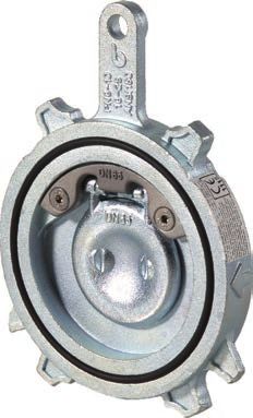
Serie 06-M6
Valvola di ritegno a clapet wafer / Swing wafer check valve
Le valvole serie 06 sono valvole di ritegno a clapet wafer The valves in series 06 are swing wafer check valves, manu-
realizzate in accordo alle normative di prodotto rilevanti ed factured in accordance with the most severe product norms
al sistema di gestione della qualità EN ISO 9001. and in conformity with the quality requirements of EN ISO
Sono disponibili nelle versioni: 9001.
06-M6.4 > in acciaio al carbonio idonee per riscaldamen- They are available in the following versions:
to e condizionamento (HVAC), trattamento e distribuzione 06-M6.4 > with carbon steel body suitable for heating and
dell’acqua, applicazioni, agricole, per aria compressa, olii conditioning purposes (HVAC), water treatment and distribu-
e idrocarburi. tion, agricultural applications, compressed air circuits, oils
06-M6.6 > con corpo in acciaio inossidabile CF8M per im- and hydrocarbons.
pianti chimici, alimentari e industriali in genere. 06-M6.6 > in stainless steel CF8M suitable for chemical
(Fatta salva la scelta corretta dell’articolo in base all’appli- plants, food processing and general industrial purposes.
cazione) (Please ensure the choice of the corresponding item)
Sono idonee: per installazione in posizione orizzontale o YES: for installing in horizontal or vertical position.
verticale.
Certificazioni / Certifications
Conformi alla direttiva 2014/68/UE (ex 97/23/CE PED) In conformity with directive 2014/68/UE (ex 97/23/CE PED)
Norme costruttive e di collaudo (equivalenti): Design and testing standards (correspondences):
Flange: EN 1092 ISO 7005, ANSI B16.5 Flanges: EN 1092 ISO 7005, ANSI B16.5
Design: EN12516, EN12334 Design: EN12516, EN12334
Marcatura: EN19 Marking: EN19
Collaudo: testate al 100% EN 12266 Testing: 100% testing in accordance with EN 12266
VALVES
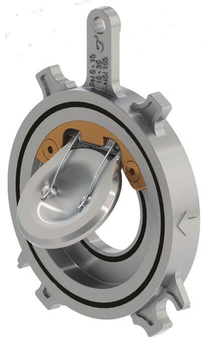
244 www.brandonivalves.comIl foro di posizionamento facilita l’in-
stallazione.
The positioning hole simplifies instal-
lation.
Il profilo particolare con alette (DN
32-250) permette l’installazione tra
flange: PN6 - 10 - 16 - 25 - ANSI 150.
The special profile with centring
lugs (DN 32-250) allows mounting
between flanges: PN6 - 10 - 16 - 25
- ANSI 150.
La molla permette l’installazione in
ogni posizione.
The spring allows mounting in all po-
sitions.
L'otturatore va in arresto contro la
tubazione, garantendo la massima
apertura possibile e minimizzando
le perdite di carico.
Disc stop against pipe walls, ensur-
ing maximum opening degree and
minimizing headlosses.
La forma bombata dell’otturatore ri-
duce le perdite dicarico e limita le
turbolenze nella zona a valle.
The rounded shape of the shutter re-
duces head losses and limits the tur-
bulence downstream..
Con l’O-Ring di tenuta non necessi-
ta di guarnizioni aggiuntive durante
l’installazione.
No need for supplementary seal-
ing during installation, thanks to the
O-ring seal.
Minimo ingombro.
Compact design.
VALVES
www.brandonivalves.com 245Serie 06-M6
Valvola di ritegno a clapet wafer / Swing wafer check valve
Corpo in acciaio-carbonio / Carbon steel body
Senza molla / Without spring Con molla / With spring
06.430 06.432 06.433 M6.430
Corpo: Acciaio-Carbonio Corpo: Acciaio-Carbonio Corpo: Acciaio-Carbonio Corpo: Acciaio-Carbonio
O-ring: NBR O-ring: FKM O-ring: PTFE O-ring: NBR
Temp: da -20 a +100°C Temp: da -20 a +150°C Temp: da -20 a +200°C Temp: da -20 a +100°C
Body: Carbon steel Body: Carbon steel Body: Carbon steel Body: Carbon steel
O-ring: NBR O-ring: FKM O-ring: PTFE O-ring: NBR
Temp: -20 +100°C Temp: -20 +150°C Temp: -20 +200°C Temp: -20 +100°C
Corpo in acciaio-carbonio / Carbon steel body Corpo in AISI 316 / Body in AISI 316
Con molla / With spring Senza molla / Without spring
M6.432 M6.433 06.620 06.622
Corpo: Acciaio-Carbonio Corpo: Acciaio-Carbonio Corpo: AISI 316 Corpo: AISI 316
O-ring: FKM O-ring: PTFE O-ring: NBR O-ring: FKM
Temp: da -20 a +150°C Temp: da -20 a +200°C Temp: da -20 a +100°C Temp: da -20 a +150°C
Body: Carbon steel Body: Carbon steel Body: AISI 316 Body: AISI 316
O-ring: FKM O-ring: PTFE O-ring: NBR O-ring: FKM
Temp: -20 +150°C Temp: -20 +200°C Temp: -20 +100°C Temp: -20 +150°C
Corpo in AISI 316 / Body in AISI 316
Senza molla / Without spring Con molla / With spring
06.623 M6.620 M6.622 M6.623
Corpo: AISI 316 Corpo: AISI 316
Corpo: AISI 316 Corpo: AISI 316 O-ring: FKM O-ring: PTFE
O-ring: PTFE O-ring: NBR Temp: da -20 a +150°C Temp: da -20 a +200°C
Temp: da -20 a +200°C Temp: da -20 a +100°C
Body: AISI 316 Body: AISI 316
Body: AISI 316 Body: AISI 316 O-ring: FKM O-ring: PTFE
O-ring: PTFE O-ring: NBR Temp: -20 +150°C Temp: -20 +200°C
Temp: -20 +200°C Temp: -20 +100°C
VALVES
246 www.brandonivalves.com06-M6 DN32 - 250
1
5
H
6
8
3
2
5
H1
P
Q A
C
7
06-M6 DN300 - 400
4
8
2
1
5
5
Q A P
C
Dimensioni (mm) / Dimensions (mm)
DN 32 40 50 65 80 100 125 150 200 250 300 350 400
P 20 26,5 33 43 53 75 96 118 164 200 245 284 323
A 16 16 18,5 18,5 22 23,5 29 34,5 36 38 32 38 42
C 77 86,5 99 118 134 154 184 208 264 317 380 440 490
H 83,5 88,75 98,5 107 115 131 138 137 169 247 - - -
H1 45 49 53 63 73 92 119 149 167 140 - - -
Q* 21 24 36 49 58 77 95 117 151 183 243 260 306
*Valore di massima. La quota effettiva dipende dalle dimensioni del tubo.
*For information maximum dimension. Actual dimension depend on pipe dimension.
Peso (kg) / Weight (kg)
kg 0,43 0,54 0,82 1,25 1,86 2,42 3,1 5,3 8,5 12,4 17,6 27,8 36,1
Tabella di compatibilita flange / Flange Compatibility Chart
DN 32 40 50 65 80 100 125 150 200 250 300 350 400
PN 6 sì sì sì sì sì sì sì sì sì sì NO NO NO
PN 10 sì sì sì sì sì sì sì sì sì sì sì sì sì
EN1092-1
PN 16 sì sì sì sì sì sì sì sì sì sì sì sì sì
PN 25 sì sì sì sì sì sì sì sì sì sì NO NO NO
ANSI 150 ANSI B16.5 sì FF (1) sì FF (1) sì sì sì sì sì sì sì sì NO NO NO
(1) Solo faccia piana
(1) Flat face only
VALVES
www.brandonivalves.com 247Serie 06-M6
Valvola di ritegno a clapet wafer / Swing wafer check valve
Materiali / Materials
Componente - Component Materiale - Material
1 Corpo - Body Acciaio inox - Stainless steel ASTM A351 gr. CF8M / Acciaio al carbonio - Carbon
steel ASTM A216 gr. WCB
2 Disco - Disc Acciaio inox - Stainless steel ASTM A351 gr. CF8M / Acciaio al carbonio - Carbon
steel ASTM A216 gr. WCB
3 Piastrina DN32-250 - Plate DN 32-250 Acciaio inox - Stainless steel ASTM A351 gr. CF8M
4 Piastrina DN300-400 - Plate DN 300-400 Acciaio inox - Stainless steel AISI 316
5 O-Ring - O-ring NBR, FKM (Viton®), PTFE
6 Molla - Spring Acciaio inox - Stainless steel AISI 302
7 Occhiello a vite - Eyebolt Acciaio inox - Stainless steel AISI 316
8 Viti - Screw Inox A2 - Stainless steel A2
Pressione massima / Temperature Temperatura / Temperature
Tipo fluido * - Fluids * Temperatura - min ° C max°C - Max°C
Gas pericolosi - Hazardous gases NO Temperature
continuo - continuous picco - peak
Gas non pericolosi - Non-hazardous gases 25 bar DN 32-200 NBR -20 100 110
16 bar DN 250-300 FKM (Viton®) -20 150 170
12 bar DN 250-300 PTFE -20 200 -
Liquidi pericolosi - Hazardous liquids 25 bar DN 32-200 Attenzione: la pressione massima di utilizzo diminuisce con la temperatura,
16 bar DN 250-400 vedi diagramma “Pressione/Temperatura”
NB: the maximum working pressure decreases while the temperature increases;
Liquidi non pericolosi - Non-hazardous liquids 25 bar DN 32-200 please refer to “pressure/temperature” chart
16 bar DN 250-400
Acqua** 25 bar DN 32-200
Water** 16 bar DN 250-400
* gas, liquidi pericolosi secondo 2014/68/EU e 1272/2008 (CLP)
** Per la raccolta, distribuzione e deflusso di acqua (PED 2014/68/EU 1.1.2b)
* hazardous gas, liquids acc. 2014/68/EU e 1272/2008 (CLP)
** For supply, distribution and discharge of water (PED 2014/68/EU 1.1.2b)
Pressione minima / Minimum pressure vd. tabella / refer to chart
Contropressione minima / Minimum counterpressure 0,3 bar
VALVES
248 www.brandonivalves.comDiagramma Pressione/Temperatura
Pressure/temperature chart
14 32 68 104 140 176 212 248 284 320 356 392 °F
bar psi
30 435
20 290
10 145
-10 0 20 40 60 80 100 120 140 160 180 200 °C
Pressione minima di apertura (mmH2O) / Cracking pressure (mmH2O)
Direzione flusso DN 32 40 50 65 80 100 125 150 200 250 300 350 400
Flow direction
con molla 321 210 194 198 196 174 226 230 244 260
with spring
con molla 242 138 126 130 120 106 126 130 136 138
with spring
senza molla 80 73 70 70 76 68 100 100 110 122 92 93 91
without spring
VALVES
www.brandonivalves.com 249Serie 06-M6
Valvola di ritegno a clapet wafer / Swing wafer check valve
Perdite di carico Fluido: acqua (1m H2O = 0,098bar)
Head loss Fluid: water (1m H2O = 0,098bar)
0
0
0
0
0
5
80
50
10
40
32
30
25
15
65
20
12
m H2O
DN
DN
DN
DN
DN
DN
DN
DN
DN
DN
DN
20
350
DN
10
8
400
6
DN
5
4
3
2
1
0,8
0,6
0,5
10 20 30 50 100 200 300 500 1000 2000 5000 mc/h
Tabella Kv - DN / Kv-DN chart
DN 32 40 50 65 80 100 125 150 200 250 300 350 400
. . . . .
Kv mc/h 13 24 41 75 140 208 341 525 1 093 1 670 2 050 3 850 4 840
VALVES
250 www.brandonivalves.comIstruzioni e Avvertenze per le serie 06-M6 Instructions and Recommendations for
series 06-M6
STOCCAGGIO STORING
Conservare in ambiente chiuso e asciutto. Keep in a closed and dry place.
MANUTENZIONE MAINTENANCE
La valvola non prevede manutenzione. The valve does not require maintenance.
AVVERTENZE RECOMMENDATIONS
Prima di procedere a qualunque intervento di manutenzione o Before carrying out maintenance or dismantling the valve:
smontaggio: - be sure that the pipes, valves and fluids have cooled down,
- attendere il raffreddamento di tubazioni, valvola e fluido - decrease the pressure and drain the lines and pipes in case of toxic,
- scaricare la pressione e drenare linea e tubazioni in presenza di corrosive, inflammable or caustic liquids.
fluidi tossici, corrosivi, infiammabili o caustici. Temperatures above 50°C and below 0°C might cause damage to pe-
Temperature oltre i 50°C e sotto gli 0° C possono causare danni alle ople.
persone.
INSTALLATION
INSTALLAZIONE - To allow the disc complete opening, provide enoigh free space down
- Prevedere un adeguato spazio libero a valle per consentire la cor- stream (see Q, dimension table).
retta apertura del clapet (tabella dimensioni, quota Q). - Handle with care.
- Maneggiare con cura. - Be sure to install in accordance with the flow direction.
- Montare nel senso corretto. - Do not weld the flanges to the piping after installing the valve.
- Le flange non devono essere saldate alle tubazioni dopo che la - Water hammers might cause damage and ruptures. Inclination,
valvola è stata installata. twisting and misalignments of the piping may subject the installed
- I colpi d’ariete possano causare danni e rotture. Inclinazioni, tor- valve to excessive stresses. It is recommended that elastic joints be
sioni e disallineamenti delle tubazioni possono causare sollecita- used in order to reduce such effects as much as possible.
zioni improprie sulla valvola una volta installata. Raccomandiamo di - When working with high temperature fluids, take care not to burn
evitarli per quanto possibile o adottare giunti elastici che possano yourself
attenuarne gli effetti. - Do not dismantle or maintain the valve while the plant is under pres-
- In caso di utilizzo con fluidi a temperatura elevata prestare atten- sure
zione al rischio di ustioni al contatto. - Use the “O” hole for harnessing and lifting.
- Non smontare o eseguire interventi di manutenzione con impianto
in pressione. NOTE. This valve is unidirectional: install in accordance with the flow
- Utilizzare il foro “O” per l’imbragatura- sollevamento. direction arrow indicated on the body.
NOTA. Questa valvola è unidirezionale: installare secondo il senso INSTALLATION
del flusso indicato sul corpo. - Install near the counter flanges, leaving a space in which to place
the valve.
MONTAGGIO - Place 2 bolts in the lower holes of the flanges, and position the valve,
- Avvicinare le controflange lasciando un gioco G adeguato al mon- placing the centring lugs 2 (for DN 32-250) or the body of the valve (DN
taggio della valvola. 300-400) on the bolts.
- Posizionare 2 bulloni nei fori inferiori delle flange e posizionare la - Insert the remaining bolts. Check that the valve is correctly aligned
valvola appoggiando le alette 2 (per DN32-250) o il corpo valvola and tighten the bolts crosswise.
(per DN300-400) sui bulloni.
- Montare i restanti bulloni. Verificare il corretto allineamento con-
centricità e serrare a croce i bulloni.
Tabella di compatibilita flange / Flange Compatibility Chart
DN 32 40 50 65 80 100 125 150 200 250 300 350 400
PN 6 sì sì sì sì sì sì sì sì sì sì NO NO NO
PN 10 sì sì sì sì sì sì sì sì sì sì sì sì sì
EN1092-1
PN 16 sì sì sì sì sì sì sì sì sì sì sì sì sì
PN 25 sì sì sì sì sì sì sì sì sì sì NO NO NO
ANSI 150 ANSI B16.5 sì FF (1) sì FF (1) sì sì sì sì sì sì sì sì NO NO NO
(1) : Solo faccia piana / Flat face only
VALVES
www.brandonivalves.com 251SMALTIMENTO DISPOSAL
Se la valvola opera a contatto con fluidi tossici o pericolosi, prende- For valve operating with hazardous media (toxic, corrosive…) , if there is
re le necessarie precauzioni ed effettuare pulizia dai residui even- a possibility of residue remaining in the valve, take due safety precau-
tualmente intrappolati nella valvola. Il personale addetto deve esse- tion and carry out required cleaning operation. Personnel in charge
re adeguatamente istruito ed equipaggiato dei necessari dispositivi must be trained and equipped with appropriate protection devices.
di protezione. Prior to disposal, disassemble the valve and separate the component
Prima dello smaltimento, smontare la valvola e suddividere i com- according to various materials. Please refer to product literature for
ponenti in base al tipo di materiale. Consultare le schede prodotto more information. Forward sorted material to recycling (e.g. metallic
per maggiori informazioni. Avviare i materiali così suddivisi al rici- materials) or disposal, according to local and currently valid legisla-
claggio (per es. materiali metallici) o allo smaltimento, in accordo tion and under consideration of the environment.
alla legislazione locale in vigore e nel rispetto dell’ambiente.
I dati e le caratteristiche di questo catalogo sono forniti a titolo indicativo. La Brandoni S.p.A. si riserva di modificare una o più caratteristiche delle valvole senza preavviso. Per maggiori
informazioni www.brandonivalves.it.
Brandoni SpA reserves the right to make changes in design and/or construction of the products at any time without prior notice. For further information, please refer to www.brandonivalves.it
VALVES
252 www.brandonivalves.comPuoi anche leggere