ACTUATOR ACCESSORIES CATALOGUE - LEADERCOM
←
→
Trascrizione del contenuto della pagina
Se il tuo browser non visualizza correttamente la pagina, ti preghiamo di leggere il contenuto della pagina quaggiù

ACTUATOR ACCESSORIES CATALOGUE
OMAL S.p.A.

                                                                                                                                           Indice Accessori Attuatori
                                                                                                                                                          Actuator Accessories Index

    I dati e le caratteristiche di questo catalogo potrebbero essere variati anche senza preavviso e, pertanto, non sono vincolanti ai fini della fornitura.
                         Data and specifications here contained may be changed without notice and according to our latest improvements.
2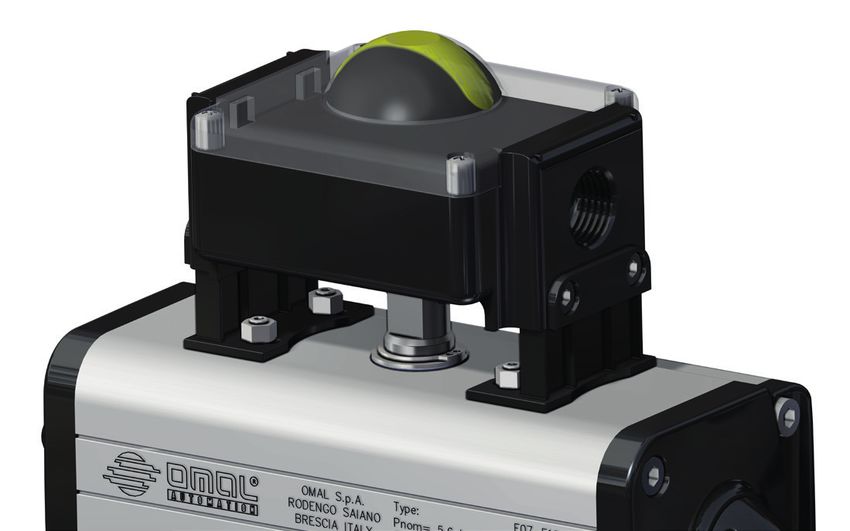
1.1                          Box di segnalazione      Pag.

                                                    Limit switch box     5

                   1.2     Finecorsa esterni e Indicatori di posizione   Pag.

                         External limit switch and Position indicators   17

                   1.3                                 Posizionatori     Pag.

                                                         Positioners     27

     AREA SICURA                           Elettrovalvole e Bobine       Pag.

     SAFE AREA
1.                 1.4
                                         Solenoid valves and Coils       37

                   1.5                         Regolatori di flusso      Pag.

                                                      Flow controls      45

                   1.6             Riduttori manuali con volantino       Pag.

                                       Manual handwheel gear box         49

                   1.7                Riduzioni e filtri silenziatori    Pag.

                                    Square reductions and Filters        55

                   2.1                          Box di segnalazione      Pag.

                                                    Limit switch box     59

                   2.2     Finecorsa esterni e Indicatori di posizione   Pag.

                         External limit switch and Position indicators   73

     AREA ATEX
     ATEX AREA
2.

                   2.3                                 Posizionatori     Pag.

                                                         Positioners     79

                   2.4                     Elettrovalvole e Bobine       Pag.

                                         Solenoid valves and Coils       87

                                                                     3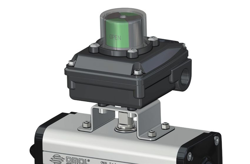
AREA SICURA
    SAFE AREA

4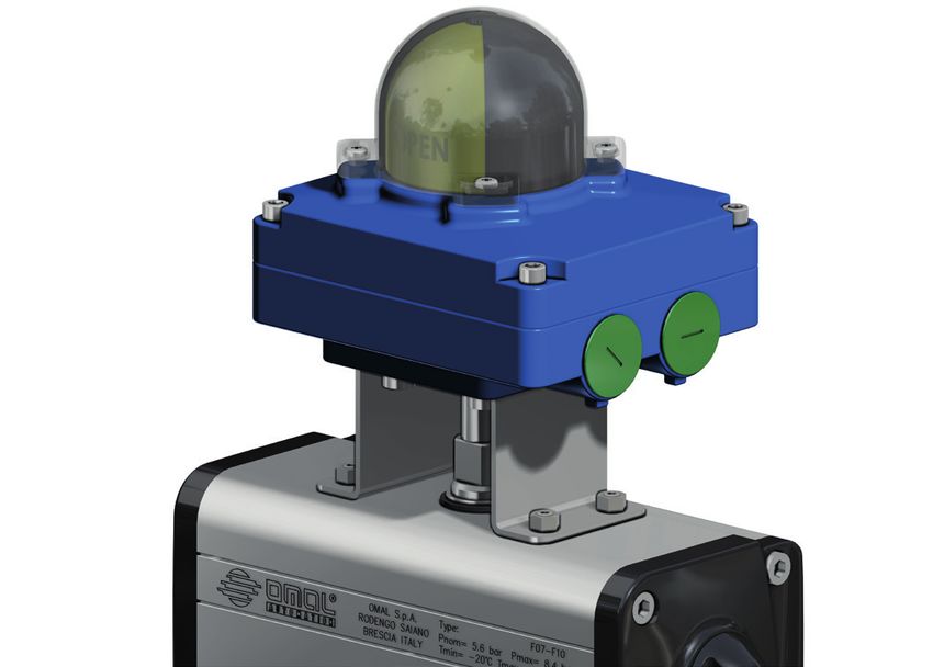
1.1 • ACTUATOR ACCESSORIES > SAFE AREA > LIMIT SWITCH BOX                                                     OMAL S.p.A.

                                                                                                                                       1.1

      Box di segnalazione
      Limit Switch Box
1.1
                                                                                                                            Pag:

                            • KSSB in alluminio e tecnopolimero con indicatore visivo                                         6
          		                 KSSB Aluminium and thermoplastic with optical indicator

                            • KSSF in alluminio con indicatore visivo                                                         7
          		                 KSSF Aluminium with optical indicator

                            • KSSP in tecnopolimero con indicatore visivo                                                     8
          		                 KSSP Thermoplastic with optical indicator

                    			                        • Tipi di finecorsa contenuti nei box KSSB - KSSF                              9
          		          		                        Types of limit switches contained in box KSSB - KSSF

           			                                 • Tipi di finecorsa contenuti nel box KSSP                                    10
          				                                  Types of limit switches contained in box KSSP

                            • KSRW in alluminio con indicatore visivo                                                        11
          		                 KSRW Aluminium with optical indicator

                    			                        • STAFFA DI CONNESSIONE tra attuatore e box finecorsa KSSB - KSSF - KSRW      12
          		         		                         CONNECTION BRACKET between actuator and KSSB - KSSF - KSRW limit switches box

                            • KS1L in alluminio con indicatore visivo                                                        13
          		                 KS1L Aluminium with optical indicator

                    			                        • Tipi di finecorsa contenuti nel box KSSP                                    14
          		          		                        Types of limit switches contained in box KSSP

                    			                        • STAFFA DI CONNESSIONE tra attuatore e box finecorsa KS1L                    15
          		          		                        CONNECTION BRACKET between actuator and KS1L limit switches box

                                                                                                                                   5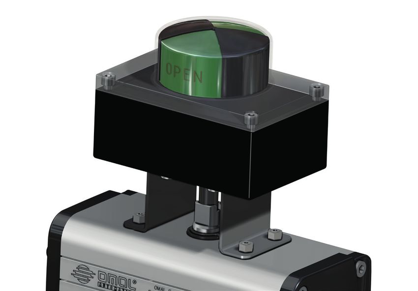
1.1 • ACTUATOR ACCESSORIES > SAFE AREA > LIMIT SWITCH BOX                                                                                                  OMAL S.p.A.

KSSB in alluminio e tecnopolimero con indicatore visivo
KSSB aluminium and thermoplastic with optical indicator

                                                                                          CODICE DI ORDINAZIONE
                                                                                          ENCODING

                                                                                               KSSB

                                                                                                                                                                           1              0
                                                                                                      N° di finecorsa            Tipo di finecorsa: pag. 9/10              2              1
                                                                                                      Number of limit switches   Type of limit switch: page 9/10                          3
                                                                                                                                                                                          4
                                                                                                                                                                                          5

                                                                                           Standard                       2             0            1
                                                                                                                          2             0            2
                                                                                                                          2             0            3
                                                                                                                          2             1            F
                                                                                                                          2             2            3
                                                                                                                          2             7            3
                                                                                                                          2             7            5
                                                                                                                          2             8            2
                                                                                                                          0             T            0

             80                                             120                                                                                      Filettatura serracavo: pag. 12
                                                                                                                                                     Cable gland thread: page 12

                                                                                                                                                         Tipo di staffa per attuatore: pag. 12
                                                                                                                                                         Type of actuator bracket: page 12
                                  Y
                                  TR
                               EN
                              E
                            BL
                           A
                          C

                                                                                   90
                                                                                   25

                                                                  12
                                                           4

                                               Per misure staffa vedi pag.10
                                               Bracket dimension see page 10

    CARATTERISTICHE PRINCIPALI                                                          TECHNICAL FEATURES
    •   Realizzato per verificare facilmente la posizione visiva ed elettrica di ogni   •   Made to easily verify the visual and electrical position of each valve even
        valvola anche da lunghe distanze.                                                   from long distances.
    •   Costruito a norme VDI/VDE 3845 standard. (EN15714-3)                            •   Built according to VDI / VDE 3845 standards. (EN15714-3)
    •   Può contenere al suo interno due finecorsa di segnalazione sia di tipo          •   It can contain two limit switches either mechanical "SPDT" or proximity.
        meccanico “SPDT” che di prossimità.                                             •   The cam of limit switch cannot slide since their regulation or other tools.
    •   Le camme di azionamento del finecorsa sono senza possibilità di slittamento     •   The pre-wiring is realized means of numbered terminals: n ° 6 for the two
        in quanto la regolazione è assicurata da scanalature sull’albero portante           microswitches, and extra poles for eventual solenoid wiring (see wiring
        senza bisogno di viti di fissaggio o altri utensili.                                diagrams).
    •   Il precablaggio è realizzato con morsetti numerati: n° 6 per i due              •   N. 2 threaded electrical connections for cable gland
        microinterruttori, ed extra poli per eventuale cablaggio dell’elettrovalvola    •   Operating temperature: from -20 ° C to + 80 ° C.
        (vedere schemi elettrici).                                                      •   Protection rate: IP 67
    •   N° 2 connesioni elettriche filettate per serracavo.
    •   Temperatura di esercizio: da -20°C a +80°C.
    •   Grado di Protezione: IP 67
    MATERIALI                                                                           MATERIALS
    •   Corpo: alluminio pressofuso rivestito con polvere di poliestere.                •   Body: die-cast aluminum coated with polyester powder.
    •   Coperchio e indicatore: policarbonato resistente UV e autoestinguente           •   Cover and Indicator: UV-resistant and self-extinguishing polycarbonate class
        classe V0.                                                                          V0.
    •   Albero: acciaio inossidabile                                                    •   Shaft: Stainless steel
    •   Viti: acciaio inossidabile                                                      •   Screws: Stainless steel
    CERTIFICAZIONI                                                                      CERTIFICATIONS
    •    Dichiarazione di conformità CE a richiesta                                     •   CE declaration of conformity on request

6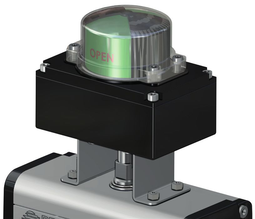
1.1 • ACTUATOR ACCESSORIES > SAFE AREA > LIMIT SWITCH BOX                                                                                             OMAL S.p.A.

                                                                                                                                                                                                 1.1

KSSF in alluminio con indicatore visivo
KSSF aluminium with optical indicator

                                                                                          CODICE DI ORDINAZIONE
                                                                                          ENCODING

                                                                                               KSSF

                                                                                                       N° di finecorsa            Tipo di finecorsa: pag. 9/10          1                0
                                                                                                       Number of limit switches   Type of limit switch: page 9/10       2                1
                                                                                                                                                                                         3
                                                                                                                                                                                         4
                                                                                                                                                                                         5

                                                                                            Standard                        2            0            1
                                                                                                                            2            0            2
                                                                                                                            2            0            3
                                                                                                                            2            1            F
                                                                                                                            2            2            3
                                                                                                                            2            7            3
                                                                                                                            2            7            5
                                                                                                                            2            8            2
              80                                         120                                                                0            T            0

                                                                                                                                                     Filettatura serracavo: pag. 12
                                                                                                                                                     Cable gland thread: page 12
                                  Y
                                  TR
                               EN

                                                                                                                                                       Tipo di staffa per attuatore: pag. 12
                              E
                            BL

                                                                                                                                                       Type of actuator bracket: page 12
                           A
                          C

                                                                                90
                                                                                25

                                                               12
                                                        4

                                              Per misure staffa vedi pag.10
                                              Bracket dimension see page 10

 CARATTERISTICHE PRINCIPALI                                                             TECHNICAL FEATURES
 •      Realizzato per verificare facilmente la posizione visiva ed elettrica di ogni   •   Made to easily verify the visual and electrical position of each valve even
        valvola anche da lunghe distanze.                                                   from long distances.
 •      Costruito a norme VDI/VDE 3845 standard. (EN15714-3)                            •   Built according to VDI / VDE 3845 standards. (EN15714-3)
 •      Può contenere al suo interno due finecorsa di segnalazione sia di tipo          •   It can contain two limit switches either mechanical "SPDT" or proximity.
        meccanico “SPDT” che di prossimità.                                             •   The cam of limit switch cannot slide since their regulation or other tools.
 •      Le camme di azionamento del finecorsa sono senza possibilità di                 •   The pre-wiring is realized means of numbered terminals: n ° 6 for the two
        slittamento in quanto la regolazione è assicurata da scanalature sull’albero        microswitches, and extra poles for eventual solenoid wiring (see wiring
        portante senza bisogno di viti di fissaggio o altri utensili.                       diagrams).
 •      Il precablaggio è realizzato con morsetti numerati: n° 6 per i due              •   N. 2 threaded electrical connections for cable gland
        microinterruttori, ed extra poli per eventuale cablaggio dell’elettrovalvola    •   Operating temperature: from -20 ° C to + 80 ° C.
        (vedere schemi elettrici).                                                      •   Protection rate: IP 67
 •      N° 2 connesioni elettriche filettate per serracavo
 •      Temperatura di esercizio: da -20°C a +80°C
 •      Grado di Protezione: IP 67
 MATERIALI                                                                              MATERIALS
 •      Corpo e coperchio: alluminio pressofuso rivestito con polvere di poliestere*.   •     Body and cover: die-cast aluminum coated with polyester powder *.•
 •      Indicatore: policarbonato resistente UV e autoestinguente classe V0             •     Indicator: UV-resistant and self-extinguishing polycarbonate class V0.
 •      Albero: acciaio inossidabile                                                    •     Shaft: Stainless steel
 •      Viti: acciaio inossidabile                                                      •     Screws: stainless steel
 * A richiesta anche in acciaio inox CF8M                                               * On request also in stainless steel CF8M
 CERTIFICAZIONI                                                                         CERTIFICATIONS
 •       Dichiarazione di conformità CE a richiesta                                     •     CE declaration of conformity on request

                                                                                                                                                                                             7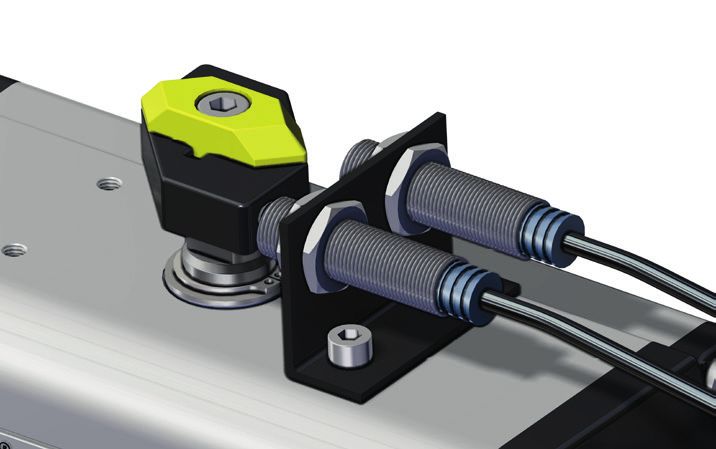
1.1 • ACTUATOR ACCESSORIES > SAFE AREA > LIMIT SWITCH BOX                                                                                                                 OMAL S.p.A.

KSSP in tecnopolimero con indicatore visivo
KSSP thermoplastic with optical indicator

                                                                                                          CODICE DI ORDINAZIONE
                                                                                                          ENCODING

                                                                                                               KSSP                                                                                  8

                                                                                                                      N° di finecorsa              Tipo di finecorsa: pag. 10           1
                                                                                                                      Number of limit switches     Type of limit switch: page 10        2

                                                                                                           Standard                         2             0            1
                                                                                                                                            2             7            3

                                                                                                                                                                    Filettatura serracavo: pag. 12
                                                                                                                                                                    Cable gland thread: page 12

           82                                            117

                                                                                                                                                 Staffa per attuatore (DAN15÷DA8000 - SRN15÷SR4000)
                                   TRY                                                                                                           Actuator bracket (DAN15÷DA8000 - SRN15÷SR4000)
                                 EN
                            LE
                        CAB
                                           65.5

                                                                          85.5
                                                                     47

                                                                                 95.5
                                                                                        105.5

                                                                                                115.5
                                           20
                                      30

                                                               18
                              40
                         50

                                                     4

                                                         80
           30                                            130

    CARATTERISTICHE PRINCIPALI                                                                          TECHNICAL FEATURES
    •  Realizzato per verificare facilmente la posizione visiva ed elettrica di ogni                    •   Made to easily verify the visual and electrical position of each valve even
       valvola anche da lunghe distanze.                                                                    from long distances.
    •  Costruito a norme VDI/VDE 3845 standard. (EN15714-3)                                             •   Built according to VDI / VDE 3845 standards. (EN15714-3)
    •  Può contenere al suo interno due finecorsa di segnalazione sia di tipo                           •   It can contain two limit switches either mechanical "SPDT" or proximity.
       meccanico “SPDT” che di prossimità.                                                              •   The cam of limit switch cannot slide since their regulation or other tools.
    •  Le camme di azionamento del finecorsa sono senza possibilità di                                  •   The pre-wiring is realized means of numbered terminals: n ° 6 for the two
       slittamento in quanto la regolazione è assicurata da scanalature sull’albero                         microswitches, and extra poles for eventual solenoid wiring (see wiring
       portante senza bisogno di viti di fissaggio o altri utensili.                                        diagrams).
    •  Il precablaggio è realizzato con morsetti numerati: n° 6 per i due                               •   N. 1 threaded electrical connection for cable gland
       microinterruttori.                                                                               •   Operating temperature: from -15 ° C to + 80 ° C.
    •  N° 1 connesione elettrica filettata per serracavo                                                •   Protection rate: IP 65
    •  Temperatura di esercizio: da -15°C a +80°C
    •  Grado di Protezione: IP 65
    MATERIALI                                                                                           MATERIALS
    •  Corpo: Etere polifenile rinforzato autoestinguente V0                                            •   Body: reinforced polyphenylene ether flame retardant V0
    •  Coperchio e indicatore: policarbonato resistente UV e autoestinguente V0                         •   Cover and Indicator: UV-resistant and self-extinguishing polycarbonate class
    •  Albero: tecnopolimero rinforzato                                                                     VO
    •  Viti: acciaio inossidabile                                                                       •   Shaft: reinforced polymer
                                                                                                        •   Screws: stainless steel
    CERTIFICAZIONI                                                                                      CERTIFICATIONS
    •   Dichiarazione di conformità CE a richiesta                                                      •   CE declaration of conformity on request

8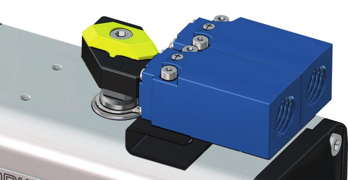
1.1 • ACTUATOR ACCESSORIES > SAFE AREA > LIMIT SWITCH BOX                                                                                  OMAL S.p.A.

                                                                                                                                                                1.1

tipi di finecorsa contenuti nei box KSSB - KSSF
types of limit switches contained in box KSSB - KSSF

                                                    DESCRIZIONE                                                     VERSIONE       COLLEGAMENTO ELETTRICO
  CODE*
                                                    DESCRIPTION                                                      VERSION           WIRING DIAGRAM

                Microinterruttori elettromeccanici SPDT con contatti argentati (CHERRY)
                SPDT Electromechanical microswitches with silver plated contacts (CHERRY)                             Di serie
      01
                                                                                                                     Standard
                Max: 250 Vac 5A -24 Vdc 3A; Min: 250 Vac 50 mA - 24 Vdc 50 mA. (resisive load)

                Microinterruttori elettromeccanici SPDT con contatti dorati sigillati ermeticamente
                (MATSUSHITA)
                SPDT Electromechanical microswitches with gold plated contacts hermetically sealed                   A richiesta
      02
                (MATSUSHITA)                                                                                         On request

                Max: 250 Vac 3A - 24 Vdc 1A; Min: 250 Vac 5 mA - 24 Vdc 1 mA.

                Microinterruttori elettromeccanici SPTD con contatti dorati (CHERRY)
                SPDT Electromechanical microswitches SPDT with gold plated contacts (CHERRY)                         A richiesta
      03
                                                                                                                     On request
                Max: 250 Vac 3A - 24 Vdc 1A; Min: 250 Vac 5 mA - 24 Vdc 1 mA.

                Microinterruttori elettromeccanici DPDT con contatti argentati, (ogni camma aziona 2
                microinterruttori SPDT contemporaneamente) (CHERRY)
                DPDT Electromechanical microswitches with silver plated contacts (each cam actuates 2                A richiesta
      1F
                SPDT microswitches simultaneously) (CHERRY)                                                          On request

                 Max: 250 Vac 5A - 24 Vdc 5A; Min: 24 Vdc 50 mA

                Microinterruttori di prossimità amplificati 3 fili NO P+F NBN4 12GM50 E2, PNP
                3-wire amplified proximity microswitches NO NBN4 12GM50 E2 P+F, PNP                                  A richiesta
      23
                                                                                                                     On request
                10÷30 Vdc; 200 mA

                Microinterruttori di prossimità amplificati 3 fili PNP NO P+F NBB2 V3 E2,
                3-wire amplified proximity microswitches PNP NO P+F NBB2 V3 E2,                                      A richiesta
      73
                                                                                                                     On request
                10÷30 VDC; 100 mA - opereting current 0 - 100 mA

* La sigla che identifica il tipo di finecorsa usati, compare nel codice del box al 6° e 7° posto.
* The symbol that identifies the type of limit switches used, appears in the code box in the 6th and 7th position

                                                                                                                                                            9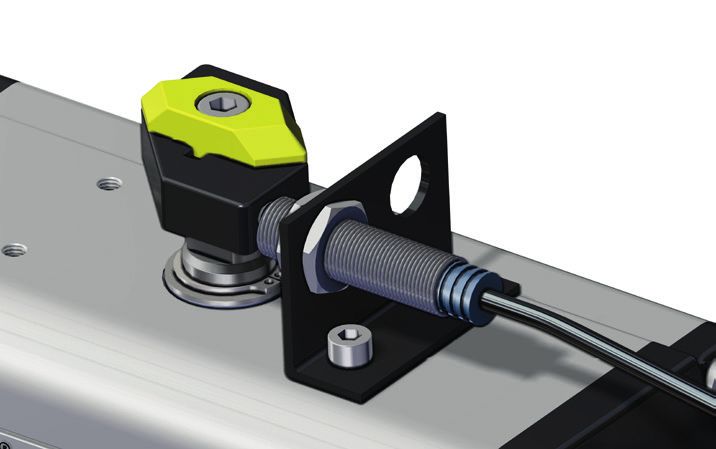
1.1 • ACTUATOR ACCESSORIES > SAFE AREA > LIMIT SWITCH BOX                                                                        OMAL S.p.A.

                Microinterruttori di prossimità amplificati IFM IS 5026, 2 fili
                2-wire amplified proximity microswitches IFM IS 5026                                                 A richiesta
      75
                                                                                                                     On request
                5÷36 Vdc; 4÷200 mA

                Microinterruttori pneumatici 3 vie N.C. 0÷8 bar                                                      A richiesta
      82
                3 way pneumatic microswitches N.C. 0 ÷ 8 bar                                                         On request

                Segnale analogico 4-20 mA. Alimentazione 12÷30 Vdc, linearità +/- 0,5% del fondo
                scala. Azione diretta o inversa. Logica di processo secondo ASIC-CMOS.                               A richiesta
      T0
                4-20 mA analog output. Supply voltage 12÷30 Vdc; linearity +/- 0,5% on full scale; direct or         On request
                inverse actions; logic processor ASIC - CMOS

tipi di finecorsa contenuti nel box KSSP
types of limit switches contained in box KSSP

                                                    DESCRIZIONE                                                     VERSIONE       COLLEGAMENTO ELETTRICO
  CODE*
                                                    DESCRIPTION                                                      VERSION           WIRING DIAGRAM

                Microinterruttori elettromeccanici SPDT con contatti argentati (CHERRY)
                SPDT Electromechanical microswitches with silver plated contacts (CHERRY)                             Di serie
      01
                                                                                                                     Standard
                Max: 250 Vac 5A -24 Vdc 3A; Min: 250 Vac 50 mA - 24 Vdc 50 mA. (resisive load)

                Microinterruttori di prossimità amplificati 3 fili PNP NO P+F NBB2 V3 E2,
                3-wire amplified proximity microswitches PNP NO P+F NBB2 V3 E2,                                      A richiesta
      73
                                                                                                                     On request
                10÷30 VDC; 200 Ma - opereting current 0 - 100 mA

* La sigla che identifica il tipo di finecorsa usati, compare nel codice del box al 6° e 7° posto.
* The symbol that identifies the type of limit switches used, appears in the code box in the 6th and 7th position

10
1.1 • ACTUATOR ACCESSORIES > SAFE AREA > LIMIT SWITCH BOX OMAL S.p.A.
1.1
KSRW in alluminio con indicatore visivo
KSRW aluminium with optical indicator
CODICE DI ORDINAZIONE
ENCODING
KSRW 2 0 1B 2
0
N° di finecorsa 1
Number of limit switches
3
4
5
Finecorsa meccanico SPDT Honeywell V15505-CZ100A05-01
contatto dorato, 5A 125-250 Vac, 0,1A 30Vdc
SPDT mechanical limit switch Honeywell, gold-plated contact, 5A
125-250 Vac, 0,1A 30Vdc
Filettatura serracavo: M20x1,5
Cable gland thread: M20x1,5
Tipo di staffa per attuatore: pag. 12
Type of actuator bracket: page 12
105 105 120 120 COLLEGAMENTO ELETTRICO
WIRING DIAGRAM
Y Y
TR TR
EN EN
LE LE
110
110
B B
CA CA
25
25
12 12
4 4
Per misure staffa
Per misure
vedi pag.10
staffa vedi pag.10
Bracket dimension
Bracketsee
dimension
page 10 see page 10
CARATTERISTICHE PRINCIPALI TECHNICAL FEATURES
• Camme colorate facilmente regolabili • Easily adjustable colored cams
• Facilità di settaggio camme con sistema anti vibrazione • Ease of setting cams with anti-vibration system
• Assenza di fili elettrici interni. I collegamenti elettrici sono realizzati • No internal electrical wires. The electrical connections are made through
tramite circuito stampato, fino ad un massimo di corrente di 5A. a printed circuit, up to a maximum current of 5A. Protection against short
Protezione contro corto circuito circuit
• 3 connessioni elettriche standard disponibili con filettature M20x1,5; ½” • N. 3 standard electrical thread connections standard M20x1,5; ½ "NPT-F on
NPT-F a richiesta. request.
• Interasse di fissaggio Namur (UNC a richiesta) • Namur and UNC mounting standard
• Morsettiera interna su circuito stampato per collegamento elettrovalvola • Internal terminal on printed circuit board for connecting solenoid valve
• Temperatura ambiente: da -20°C a +80°C; a richiesta da -40°C a +120°C. • Ambient temperature: from -20 ° C to + 80 ° C; on request from -40 ° C to +
• Grado di protezione IP67 120 ° C.
• Protection rate IP67
MATERIALI MATERIALS
• Corpo e coperchio: alluminio pressofuso verniciato a polvere per resistere • Body and cover: die-cast aluminum powder coated to resist against
alla corrosione corrosion
• Indicatore: policarbonato, resistente agli urti • Indicator: polycarbonate, shock resistant
• Albero e viti: acciaio inox • Tree and screws: stainless steel
CERTIFICAZIONI CERTIFICATIONS
• Dichiarazione di conformità CE a richiesta • CE declaration of conformity on request
• Conformità UL 508, UL file nr. E249752 a richiesta • UL 508, UL file nr. E249752 conformity on request
111.1 • ACTUATOR ACCESSORIES > SAFE AREA > LIMIT SWITCH BOX OMAL S.p.A.
STAFFA DI CONNESSIONE tra attuatore e box finecorsa
CONNECTION BRACKET between actuator and limit switches box
KSSB - KSSF - KSRW
TIPO DI STAFFA * DESCRIZIONE
TYPE OF BRACKET* DESCRIPTION
Connessione NAMUR 25x50x20* (*20=altezza albero attuatore, quota A in figura)
0
Namur connection 25x50x20* (*20= height of the actuator shaft, dimension A as per picture)
Connessione NAMUR 30x80x20* (*20 = altezza albero attuatore, quota A in figura)
1
Namur connection 30x80x20* (*20=height of the actuator shaft, dimension A as per picture)
Connessione NAMUR 30x80x30* (*30 = altezza albero attuatore, quota A in figura)
B
3
Namur connection 30x80x30* (*30=height of the actuator shaft, dimension A as per picture)
A
Connessione NAMUR 30x80x30* (*30= altezza albero attuatore, quota A in figura)
4
Namur connection 30x80x30* (*30=height of the actuator shaft, dimension A as per picture)
Connessione NAMUR 30x130x30* (*30= altezza albero attuatore, quota A in figura)
5
Namur connection 30x130x30* (*30=height of the actuator shaft, dimension A as per picture)
C
*La staffa compare nell’ultimo carattere del codice del box per finecorsa. Per ordinare solo la staffa ricorrere al codice OMAL.
*The bracket appears in the last position of the limit switches box code. If you need to order only the bracket, please refer to the Omal code
D
PER ATTUATORI IN ALLUMINIO
FOR ALUMINIUM ACTUATORS
MISURA DAN15÷DAN120 DAN180÷DAN960 DAN1440÷DAN1920 DA2880÷DA8000
SIZE SRN15÷SRN60 SRN90÷SRN480 SRN720÷SRN960 SR1440÷SR4000
Codice Code KCPN1015 KCPN1060 KCPN2060 KCPN1A04
Tipo di staffa
1 3 4 5
Type of bracket
B
A (mm) 20 30 30 30
A
B (mm) 45 55 55 55 A
C (mm) 30 30 30 30
D (mm) 80 80 80 130
C
PER ATTUATORI IN ACCIAIO INOX
FOR STAINLESS STEEL ACTUATORS D
MISURA DAN15÷DNA30 DAN60 DAN120÷DAN960 DAN1440÷DAN1920
SIZE SRN15** SRN30 SRN60÷SRN480 SRN720÷SRN960
Codice Code KCPN0015 KCPN1060 KCPN2060
Tipo di staffa
0 0 3 4
Type of bracket
A (mm) 20 20 30 30
B (mm) 45 45 55 55
C (mm) 25 25 30 30
D (mm) 50 50 80 80
A
** Previo utilizzo interfaccia per attuatore KBVI4015
** Use connection bracket for actuator: KBVI4015 Per "Tipo di staffa" codice 4
For "Type of bracket" code 4
FILETTATURE DEL SERRACAVO DEL BOX
THREADS OF BOX CABLE GLANDS
Tipo di filettatura del serracavo*** Descrizione
Type of cable gland thread*** Description
1 1/2” NPT A RICHIESTA ON REQUEST
2 M 20x1,5 STANDARD
***La filettatura compare nell’ottavo carattere del codice del box per finecorsa, tranne per il tipo KSRW che compare nel nono carattere.
***The thread appears in the 8th position of the limit switches box code, a part from KSRW type wich appears on 9th position.
121.1 • ACTUATOR ACCESSORIES > SAFE AREA > LIMIT SWITCH BOX OMAL S.p.A.
1.1
KS1L in alluminio con indicatore visivo
KS1L aluminium with optical indicator
CODICE DI ORDINAZIONE
ENCODING
KS1L
N° di finecorsa Tipo di finecorsa: pag. 14 1 0
Number of limit switches Type of limit switch: page 14 2 1
3
4
5
Standard 2 M 0
2 M 1
2 H 1
2 6 0
2 7 0
2 7 3
2 7 5
2 7 8
121 97
Filettatura serracavo: pag. 15
Cable gland thread: page 15
Tipo di staffa per attuatore: pag. 15
Type of actuator bracket: page 15
RY
99
NT
LE E
C AB
10
5
10
CARATTERISTICHE PRINCIPALI TECHNICAL FEATURES
• Realizzato per verificare facilmente la posizione visiva ed elettrica di ogni • Made to easily verify the visual and electrical position of each valve even
valvola anche da lunghe distanze. from long distances.
• Costruito a norme VDI/VDE 3845 standard. (EN15714-3) • Built according to VDI / VDE 3845 standards. (EN15714-3)
• Può contenere al suo interno due finecorsa di segnalazione sia di tipo • It can contain two limit switches either mechanical "SPDT" or proximity.
meccanico “SPDT” che di prossimità. • Precise cam adjustment via "Miller" system.
• Precisa regolazione delle camme tramite sistema "millerighe". • 8 positions terminal block.
• Morsettiera a 8 postazioni. • N. 2 threaded electrical connections for cable gland.
• N° 2 connesioni elettriche filettate per serracavo. • Operating temperature: from -20 ° C to + 80 ° C (NBR).
• Temperatura di esercizio STD: da -20°C a +80°C (NBR). • Protection rate: IP 67.
• Grado di Protezione: IP 67. • On request: from -20 ° C to + 80 ° C (Silicone).
• A richiesta: da -40°C a +80°C (Silicone)
MATERIALI MATERIALS
• Corpo e coperchio: alluminio pressofuso a basso contenuto di rame rivestito • Body and cover: Copper Aluminum Die Coated with Double Epoxy Coating*.
con doppio strato di verniciatura epossidica nera*. • Indicator: polycarbonate and ABS
• Indicatore: policarbonato e ABS. • Shaft: Stainless steel
• Albero: acciaio inossidabile. • Screws: Stainless steel
• Viti: acciaio inossidabile. * Also in stainless steel CF8M on request
* A richiesta anche in acciaio inox CF8M.
CERTIFICAZIONI CERTIFICATIONS
• Dichiarazione di conformità CE a richiesta • CE declaration of conformity on request
131.1 • ACTUATOR ACCESSORIES > SAFE AREA > LIMIT SWITCH BOX OMAL S.p.A.
tipi di finecorsa contenuti nei box KS1L
types of limit switches contained in box KS1L
DESCRIZIONE VERSIONE COLLEGAMENTO ELETTRICO
CODE*
DESCRIPTION VERSION WIRING DIAGRAM
Microinterruttori elettromeccanici SPDT con contatti argentati (OMRON SS-5)
SPDT Electromechanical microswitches with silver plated contacts (OMRON SS-5) Di serie
M0
Standard
Max: 250 Vac 3A - 30 Vdc 3A
Microinterruttori elettromeccanici SPTD con contatti dorati (OMRON SS-01)
SPDT Electromechanical microswitches SPDT with gold plated contacts (OMRON SS-01) A richiesta
M1
On request
Max: 125 Vac 0.1A - 30 Vdc 0.1A
Microinterruttori di prossimità magnetici SPDT sigillati ermeticamente (HAMLIN 59140)
Hermetically sealed SPDT magnetic proximity switches (HAMLIN 59140) A richiesta
H1
On request
Max: 120 Vac 0.18A - 175 Vdc 0.25A
Microinterruttori di prossimità NAMUR 2 fili P+F SJ 3,5 N, NC, tensione nominale 8,2V,
(tensione di esercizio 5÷25V)
2-wire NAMUR proximity limit switches SJ 3.5 N P+F, NC, nominal voltage 8,2V, (opera- A richiesta
60
ting voltage 5÷25V) On request
EEx ia IIC T6
Microinterruttori di prossimità NAMUR 2 fili P+F NJ2 V3 N, NC, 8V 2-wire NAMUR
proximity microswitches P + F NJ2 V3 N, NC, 8V A richiesta
70
On request
EEx ia IIC T6
Microinterruttori di prossimità amplificati 3 fili PNP NO P+F NBB2 V3 E2,
3-wire amplified proximity microswitches PNP NO P+F NBB2 V3 E2, A richiesta
73
On request
10÷30 VDC; 100 mA - opereting current 0 - 100 mA
Microinterruttori di prossimità amplificati IFM IS 5026, 2 fili
2-wire amplified proximity microswitches IFM IS 5026 A richiesta
75
On request
5÷36 Vdc; 4÷200 mA
BN
L+
Microinterruttori di prossimità NAMUR 2 fili P+F NCB2 V3 NO, NC tensione nominale
8.2V
A richiesta
78 2-wire NAMUR proximity microswitches P + NCB2 V3 NO, NC unamplified, NC, 8.2V
On request
EEx ia IIC T6
BU
L-
* La sigla che identifica il tipo di finecorsa usati, compare nel codice del box al 6° e 7° posto.
* The symbol that identifies the type of limit switches used, appears in the code box in the 6th and 7th position
141.1 • ACTUATOR ACCESSORIES > SAFE AREA > LIMIT SWITCH BOX OMAL S.p.A.
1.1
STAFFA DI CONNESSIONE tra attuatore e box finecorsa
CONNECTION BRACKET between actuator and limit switches box
KS1L
TIPO DI STAFFA * DESCRIZIONE
TYPE OF BRACKET* DESCRIPTION
Connessione NAMUR 25x50x20* (*20=altezza albero attuatore, quota A in figura)
0
Namur connection 25x50x20* (*20= height of the actuator shaft, dimension A as per picture)
Connessione NAMUR 30x80x20* (*20 = altezza albero attuatore, quota A in figura)
1
Namur connection 30x80x20* (*20=height of the actuator shaft, dimension A as per picture)
B
A
Connessione NAMUR 30x80x30* (*30 = altezza albero attuatore, quota A in figura)
3
Namur connection 30x80x30* (*30=height of the actuator shaft, dimension A as per picture)
Connessione NAMUR 30x80x30* (*30= altezza albero attuatore, quota A in figura)
4
Namur connection 30x80x30* (*30=height of the actuator shaft, dimension A as per picture)
Connessione NAMUR 30x130x30* (*30= altezza albero attuatore, quota A in figura)
C
5
Namur connection 30x130x30* (*30=height of the actuator shaft, dimension A as per picture)
*La staffa compare nell’ultimo carattere del codice del box per finecorsa. Per ordinare solo la staffa ricorrere al codice OMAL. D
*The bracket appears in the last position of the limit switches box code. If you need to order only the bracket, please refer to the Omal code
PER ATTUATORI IN ALLUMINIO
FOR ALUMINIUM ACTUATORS
MISURA DAN15÷DAN120 DAN180÷DAN960 DAN1440÷DAN1920 DA2880÷DA8000
SIZE SRN15÷SRN60 SRN90÷SRN480 SRN720÷SRN960 SR1440÷SR4000
Codice Code KCPL1015 KCPL1060 KCPL2060 KCPL1A04
Tipo di staffa
1 3 4 5
Type of bracket
B
A (mm) 20 30 30 30
A
A
B (mm) 30 40 40 40
C (mm) 30 30 30 30
D (mm) 80 80 80 130
C
PER ATTUATORI IN ACCIAIO INOX
FOR STAINLESS STEEL ACTUATORS
MISURA DAN15÷DA30 DAN60 DAN120÷DAN960 DAN1440÷DAN1920 D
SIZE SRN15** SRN30 SRN60÷SRN480 SRN720÷SRN960
Codice Code KCPL0015 KCPL1060 KCPL2060
Tipo di staffa
0 0 3 4
Type of bracket
A (mm) 20 20 30 30
B (mm) 30 30 40 40
C (mm) 25 25 30 30
D (mm) 50 50 80 80
** Previo utilizzo interfaccia per attuatore KBVI4015
** Use connection bracket for actuator: KBVI4015 Per "Tipo di staffa" codice 4
A
For "Type of bracket" code 4
FILETTATURE DEL SERRACAVO DEL BOX
THREADS OF BOX CABLE GLANDS
Tipo di filettatura del serracavo*** Descrizione
Type of cable gland thread*** Description
1 1/2” NPT A RICHIESTA ON REQUEST
2 M 20x1,5 STANDARD
***La filettatura compare nell’ottavo carattere del codice del box per finecorsa.
***The thread appears in the 8th position of the limit switches box code.
1516
1.2 • ACTUATOR ACCESSORIES > SAFE AREA > EXTERNAL LIMIT SWITCH AND POSITION INDICATORS   OMAL S.p.A.

      Finecorsa esterni e Indicatori di posizione
      External Limit Switch and Position indicators
1.2

                                                                                                                   1.2
                                                                                                       Pag:

                            • KFIN Finecorsa di prossimità                                              18
          		                  KFIN Proximity limit switch

                            • Finecorsa di prossimità (kit da ordinare separatamente)                   19
          		                  Proximity limit switch (kit to be ordered separately)

                            • KFE3A Finecorsa elettromeccanico con cavo                                 20
          		                  KFE3A Electromechanical limit switch with cable

                            • KFN4 Finecorsa elettromeccanico                                           21
          		                  KFN4 Electromechanical limit switch

                            • KFN1 Finecorsa pneumatico                                                 22
          		                  KFN1 Pneumatic limit switch

                            • Kit per montaggio finecorsa                                               23
          		                  Mechanical limit switch

                            • KZN00 Protezione per finecorsa                                            24
          		                  KZN00 Switch protection

                            • Indicatore visivo di posizione                                            25
          		                  Position indicator

                                                                                                              17
1.2 • ACTUATOR ACCESSORIES > SAFE AREA > EXTERNAL LIMIT SWITCH AND POSITION INDICATORS OMAL S.p.A.
KFIN Finecorsa di prossimità
KFIN Proximity limit switch
KFIN1-KFIN2 KIT + FINECORSA
KFIN1-KFIN2 KIT + LIMIT SWITCH
Esempio Kit con 1 Finecorsa - Example Kit with 1 Limit Switch
C
B
C
B
Esempio Kit con 2 Finecorsa - Example Kit with 2 Limit Switch
A
50
A
50
26
D
26
D
TABELLA CODICI - KIT + FINECORSA CODES TABLE - KIT+LIMIT SWITCHES
Codice kit con 1 finecorsa - Code kit with1 limit switch KFIN1008 KFIN1015 KFIN1060 KFIN1960
Codice kit con 2 finecorsa - Code kit with 2 limit switches KFIN2008 KFIN2015 KFIN2060 KFIN2960
DAN15÷DAN120 DAN180÷DAN480 DAN720 ÷ DAN1920
Attuatore Actuator DA8
SRN15 ÷ SRN60 SRN90÷SRN240 SRN360 ÷ SRN960
A mm. 71 71 71 81
B mm. 34 34 44 44
C mm. 38 38 48 48
D mm. 50 50 50 50
FINECORSA DI PROSSIMITÀ - FI380012
PROXIMITY LIMIT SWITCH - FI380012
BN/2
(marrone) TABELLA CODICI - FINECORSA CODES TABLE - LIMIT SWITCHES
DAN15÷DAN120 DAN180÷DAN480 DAN720 ÷ DAN1920
N0 CA/CC Attuatore Actuator DA8
SRN15 ÷ SRN60 SRN90÷SRN240 SRN360 ÷ SRN960
BU/3
(blu)
Codice Code FI380012
Codice fornitore
XS1-M12MA230 - Telemecanique
Supplier code
CARATTERISTICHE PRINCIPALI TECHNICAL FEATURES
• Interruttore di prossimità induttivo M12 collegamento a 2 fili NO Tensione • M12 proximity limit switch with NO wire connection
di alimentazione: 24÷240V AC; 24÷210V DC. • Supply voltage: 24÷240V AC; 24÷210V DC.
• Corrente commutabile: 0,2A max • Commutable current: 0,2A max
• Grado di protezione: IP 68 • Protection rate: IP 68
• Lunghezza cavo: 3m • Cable length: 3m
• Temperatura di funzionamento: da -25°C a +70°C • Working temperature: from -25°C to +70°C
• Segnalazione stato di uscita tramite LED anulare. • Limit switch working signalled by ring LED.
• A richiesta disponibile interruttore di prossimità induttivo M18 • On request it is available an inductive limit switch M18
181.2 • ACTUATOR ACCESSORIES > SAFE AREA > EXTERNAL LIMIT SWITCH AND POSITION INDICATORS OMAL S.p.A.
Finecorsa di prossimità (kit da ordinare separatamente*)
Proximity limit switch (kit to be ordered separately*)
1.2
FINECORSA DI PROSSIMITÀ
PROXIMITY LIMIT SWITCH
CODICE DI ORDINAZIONE
ENCODING
BN
L+ FI90 12
BK
BU
L- tipo di connessione/connection type
con cavo 2 m, codice P+F: NBN4-12GM50-E2
32
2 mt. cable, P+F code: NBN4-12GM50-E2
con connettore, codice P+F: NBN4-12GM50-E2-V1
31
with connector, code P+F:NBN4-12GM50-E2-V1
CARATTERISTICHE PRINCIPALI TECHNICAL FEATURES
• .Finecorsa induttivo PNP M12 3 fili DC • 3-wire DC PNP M12 inductive limit switch
• Tensione di alimentazione: 10÷30 V DC • Suppy voltage: 10 ÷ 30 V DC
• Corrente assorbita: 0÷12 mA • Current consumption: 0 ÷ 12 mA
• Grado di protezione IP 67 • Protection rate IP 67
• Temperatura di funzionamento: da -25°C a +70°C • Working temperature: from -25°C to +70°C
• Segnalazione stato di uscita tramite LED anulare. • Limit switch working signalled by ring LED.
• Conforme alle norme EN 60947-5-2 • According to EN 60947-5-2
• Kit di montaggio da ordinare a seconda dell’altezza dell’albero attuatore.* • Mounting kit to be ordered depending on the height of the actuator shaft.*
• Per la versione con connettore è possibile ordinare anche il cavo*. • For the version with connector, you can order also the cable.*
FINECORSA DI PROSSIMITÀ
PROXIMITY LIMIT SWITCH
CODICE DI ORDINAZIONE
ENCODING
FI90 12
3/BN
L+ tipo di connessione/connection type
4/BN
L- con cavo 2 m, codice P+F: NBN4-12GM40-Z0
22
2 mt. cable, P+F code: NBN4-12GM40-Z0
con connettore, codice P+F: NBN4-12GM40-Z0-V1
21
with connector, code P+F:NBN4-12GM40-Z0-V1
CARATTERISTICHE PRINCIPALI TECHNICAL FEATURES
• Finecorsa induttivo M 12 2 fili DC • 2-wire DC M12 inductive limit switch
• Tensione di alimentazione: 6÷60 V DC • Supply voltage: 6 to 60 V DC
• Corrente assorbita: 4÷100 mA • Current consumption: 4 to 100 mA Protection rate: IP 67
• Grado di protezione IP 67 • Working temperature: from -25°C to +70°C
• Temperatura di funzionamento: da -25°C a +70°C • Limit switch working signalled by ring LED
• Segnalazione stato di uscita tramite LED anulare. • According to EN 60947-5-2
• Conforme alle norme EN 60947-5-2 • Mounting kit to be ordered depending on the height of the actuator shaft.*
• Kit di montaggio da ordinare a seconda dell’altezza dell’albero attuatore.* • For the version with connector, you can order also the cable*
• Per la versione con connettore è possibile ordinare anche il cavo.*
* Per il kit di montaggio (code: KBF85...) e per il cavo di connessione, da ordinare separatamente, vedere pag. 23.
* For mounting kit (code: KBF85...) and connection cable, to be ordered separately, see page 23.
191.2 • ACTUATOR ACCESSORIES > SAFE AREA > EXTERNAL LIMIT SWITCH AND POSITION INDICATORS OMAL S.p.A.
KFE3A Finecorsa elettromeccanico con cavo
KFE3A Electromechanical limit switch with cable
KFE3A KIT + FINECORSA
KFE3A KIT + LIMIT SWITCH
16
C
B
Esempio Kit con 1 Finecorsa - Example Kit with 1 Limit Switch
16
C
B
A
Esempio Kit con 2 Finecorsa - Example Kit with 2 Limit Switch 50
A
50
60
30
D
60
30
D
TABELLA CODICI - KIT + FINECORSA CODES TABLE - KIT+LIMIT SWITCHES
DAN15÷DAN120 DAN180÷DAN480 DAN720 ÷ DAN1920
Attuatore Actuator
SRN15 ÷ SRN60 SRN90÷SRN240 SRN360 ÷ SRN960
Codice kit con 1 finecorsa - Code kit with 1 limit switch KFE3A1015 KFE3A1120 KFE3A1720
Codice kit con 2 finecorsa - Code kit with 2 limit switches KFE3A2015 KFE3A2120 KFE3A2720
A mm. 76 76 86
B mm. 31 41 41
C mm. 38 48 48
D mm. 60 70 70
FINECORSA ELETTROMECCANICO - FE3A0000
ELECTROMECHANICAL LIMIT SWITCH - FE3A0000
BN/2 BN/2
(marrone) (marrone)
TABELLA CODICI - FINECORSA CODES TABLE - LIMIT SWITCHES
DAN15÷DAN120 DAN180÷DAN480 DAN720 ÷ DAN1920
Attuatore Actuator
SRN15 ÷ SRN60 SRN90÷SRN240 SRN360 ÷ SRN960
Codice Code FE3A0000
Codice fornitore
XCMN2110L1 - Telemecanique
Supplier code
BN/2 BN/2 BN/2
(marrone) (marrone) (marrone)
CARATTERISTICHE PRINCIPALI TECHNICAL FEATURES
• Finecorsa meccanici del tipo a pulsante conformi alle norme: • Mechanical, button limit switches as per:
• Macchine: IEC 60947-5-1, EN 60947-5-1, UL 508, CSA C22-2 n° 14 • machinery:IEC 60947-5-1, EN 60 947-5-1, UL 508, CSA C22-2 n° 14
• Prodotti: IEC 60204-1; EN 60204-1 • product: IEC 60204-1; EN 60204-1
• Corpo in tecnopolimero • Body in technopolymer
• Grado di protezione IP 65 secondo IEC 60529 • Protection: IP 65 as per IEC 60529
• Cavo d’uscita flessibile a 4 conduttori (lunghezza 1m) • Flexible output cable with 4 conductors (lenght 1 m)
• Temperatura di utilizzo: da -25°C a +70°C • Working temperature: from -25°C to +70°C
• Possono essere montati sui modelli DAN e SRN tramite un kit composto • It can be fixed on DAN and SRN models using a kit composed by plate fixed
da una basetta fissata al corpo dell’attuatore e da una camma montata to the actuator body and a cam mounted on the shaft.
sull’albero dello stesso.
201.2 • ACTUATOR ACCESSORIES > SAFE AREA > EXTERNAL LIMIT SWITCH AND POSITION INDICATORS OMAL S.p.A.
KFN4 Finecorsa elettromeccanico
KFN4 Electromechanical limit switch
1.2
KFN41 - KFN42 KIT + FINECORSA
30
KFN41 - KFN42 KIT + LIMIT SWITCH
B
C
Esempio Kit con 1 Finecorsa - Example Kit with 1 Limit Switch
30
B
C
Esempio Kit con 2 Finecorsa - Example Kit with 2 Limit Switch A
68
A
68
70
60
30
70
60
30
TABELLA CODICI - KIT + FINECORSA CODES TABLE - KIT+LIMIT SWITCHES
DAN15÷DAN120 DAN180÷DAN480 DAN720 ÷ DAN1920
Attuatore Actuator
SRN15 ÷ SRN60 SRN90÷SRN240 SRN360 ÷ SRN960
Codice kit con 1 finecorsa - Code kit with 1 limit switch KFN41015 KFN41120 KFN41960
Codice kit con 2 finecorsa - Code kit with 2 limit switches KFN42015 KFN42120 KFN42960
A mm. 90 90 100
B mm. 45 55 55
C mm. 38 48 48
D mm. 60 70 70
FINECORSA ELETTROMECCANICO -FE360000
ELECTROMECHANICAL LIMIT SWITCH - FE360000
BK BN/1
(nero) (marrone)
TABELLA CODICI - FINECORSA CODES TABLE - LIMIT SWITCHES
DAN15÷DAN120 DAN180÷DAN480 DAN720 ÷ DAN1920
Attuatore Actuator
SRN15 ÷ SRN60 SRN90÷SRN240 SRN360 ÷ SRN960
Codice Code FE360000
Codice fornitore
XCKN2110G11 - Telemecanique
Supplier code
BK BU GN/JW
(nero) (blu) (verde-giallo)
CARATTERISTICHE PRINCIPALI TECHNICAL FEATURES
• Finecorsa meccanico del tipo a pulsante conforme alle norme IEC 947-5- • Mechanical button limit switch according to IEC 947-5-1, EN 60 945-5-1, UL
1,EN 60 945-5-1,UL 508,Omologazione CSA A300-UL 300 Listed 508, CSA A300-UL 300 approved Listed
• Grado di protezione IP 67 • Protection rate: IP 67
• Ingresso cavo filettato Pg 11 • Threaded cable input Pg 11
• Temperatura di utilizzo: da -25°C a +70°C • Working temperature: from -25°C a +70°C
• Comprensivo di kit per il montaggio sui modelli DAN e SRN composto • Mounting kit included on DAN and SRN models. It is composed by a plate
da una basetta fissata al corpo dell’attuatore e da una camma montata fixed on the body of the actuator and a cam mounted on its shaft.
sull’albero dello stesso.
211.2 • ACTUATOR ACCESSORIES > SAFE AREA > EXTERNAL LIMIT SWITCH AND POSITION INDICATORS OMAL S.p.A.
KFN1 Finecorsa pneumatico
KFN1 Pneumatic limit switch
KFN11 - KFN12 KIT + FINECORSA
KFN11 - KFN12 KIT + LIMIT SWITCH
15
C
B
Esempio Kit con 1 Finecorsa - Example Kit with 1 Limit Switch
15
C
B
Esempio Kit con 2 Finecorsa - Example Kit with 2 Limit Switch A
35
A
35
70
60
30
70
60
30
TABELLA CODICI - KIT + FINECORSA CODES TABLE - KIT+LIMIT SWITCHES
DAN15÷DAN120 DAN180÷DAN480 DAN720 ÷ DAN1920
Attuatore Actuator
SRN15 ÷ SRN60 SRN90÷SRN240 SRN360 ÷ SRN960
Codice kit con 1 finecorsa - Code kit with 1 limit switch KFN11015 KFN11060 KFN11960
Codice kit con 2 finecorsa - Code kit with 2 limit switches KFN12015 KFN12060 KFN12960
A mm. 65 65 75
B mm. 32,5 40 40
C mm. 38 48 48
D mm. 60 70 70
FINECORSA PNEUMATICO - FP210000
PNEUMATIC LIMIT SWITCH - FP210000
2
A
TABELLA CODICI - FINECORSA CODES TABLE - LIMIT SWITCHES
DAN15÷DAN120 DAN180÷DAN480 DAN720 ÷ DAN1920
Attuatore Actuator
SRN15 ÷ SRN60 SRN90÷SRN240 SRN360 ÷ SRN960
Codice Code FP210000
Codice fornitore
1 3 VMW3501000100 - Metal Work
P R Supplier code
CARATTERISTICHE PRINCIPALI TECHNICAL FEATURES
• Finecorsa pneumatico miniaturizzato con attacchi a cartuccia tubo 4x2 • Miniaturized pneumatic limit switch with cartridge connections pipe 4x2
• Temperatura di utilizzo: da +5°C a +70°C • Working temperature: from +5°C to +70°C
• Pressione max. di esercizio: 10 bar • Max working pressure: 10 bar
• Fluido di alimentazione: aria filtrata e lubrificata alla temperatura di 50°C • Operating media: lubricated and filtered air at a temperature of max 50°C.
max. • Flow at 6 bar. with ∆p=1:90 NI/min
• Portata a 6 bar. con ∆p=1:90 NI/min • Bore: 2,2 mm
• Diametro di passaggio: 2,2 mm • Mounting kit included on DAN and SRN models. It is composed by a plate
• Comprensivo di kit per il montaggio sui modelli DAN e SRN composto fixed on the body of the actuator and a cam mounted on its shaft
da una basetta fissata al corpo dell’attuatore e da una camma montata
sull’albero dello stesso.
221.2 • ACTUATOR ACCESSORIES > SAFE AREA > EXTERNAL LIMIT SWITCH AND POSITION INDICATORS OMAL S.p.A.
Kit per montaggio finecorsa
Limit switch mounting kit
1.2
KBF85 KIT DI MONTAGGIO FINECORSA DI PROSSIMITÀ M2
KBF85 MOUNTING KIT PROXIMITY LIMIT SWITCH M12
TABELLA CODICI - KIT CODES TABLE - KIT
DAN15÷DAN120 DAN180÷DAN480 DAN720 ÷ DAN1920
Attuatore Actuator DA8
SRN15 ÷ SRN60 SRN90÷SRN240 SRN360 ÷ SRN960
KIT KBF85008 KBF85015 KBF85060 KBF85960
A richiesta disponibili kit per montaggio di finecorsa di prossimità M18 e misure superiori a DAN1920
On request are available kits for mounting proximity limit switches M18 e size bigger than DAN1920
KBF68 KIT PER MONTAGGIO FINECORSA ELETTROMECCANICI
KBF68 MOUNTING KIT ELECTROMECHANICAL LIMIT SWITCH
TABELLA CODICI - KIT CODES TABLE - KIT
DAN15÷DAN120 DAN180÷DAN480 DAN720 ÷ DAN1920
Attuatore Actuator
SRN15 ÷ SRN60 SRN90÷SRN240 SRN360 ÷ SRN960
KIT KBF68015 KBF68060 KBF68960
Misure superiori a DAN1920 a richiesta
Sizes over DAN1920 available on request
* Il kit non comprende le viti di fissaggio del finecorsa
* The kit does not include the fixing screws of the limit switch
CAVO DI CONNESSIONE PER FINECORSA PEPPERL+FUCHS CON USCITA CONNETTORE (MODELLO V1)
CONNECTION CABLE FOR LIMIT SWITCHES PEPPERL+FUCHS WITH CONNECTOR OUTPUT (MODEL V1)
TAGLIA - SIZE CODICE - CODE
Cavo/cable 2 m KBCP2M00
Cavo/cable 5 m KBCP5M00
231.2 • ACTUATOR ACCESSORIES > SAFE AREA > EXTERNAL LIMIT SWITCH AND POSITION INDICATORS OMAL S.p.A.
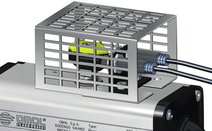
KZN00 Protezione per finecorsa
KZN00 Switch protection
A B
60
TABELLA CODICI - CODES TABLE
DAN15÷DAN180 DAN240÷DA1920
Attuatore Actuator
SRN15 ÷ SRN90 SRN120÷SRN960
KIT KZN00014 KZN00022
A mm 101 112
B mm 83 103
CARATTERISTICHE PRINCIPALI TECHNICAL FEATURES
• Protezioni per finecorsa di tipo pneumatico, meccanico e induttivo. • Protection for mechanical, pneumatic and inductive limit switches.
• Materiale: alluminio anodizzato. • Material: anodized aluminium.
241.2 • ACTUATOR ACCESSORIES > SAFE AREA > EXTERNAL LIMIT SWITCH AND POSITION INDICATORS OMAL S.p.A.
Indicatore visivo di posizione
Position indicator
1.2
INDICATORE A SEMAFORO
RED-GREEN INDICATOR
72 DESCRIZIONE
Esecuzione a semaforo con settori verdi e
rossi in policarbonato. Montaggio diretto per
attuatori a norma VDI/VDE 3845.
80
48
30
47.5
DESCRIPTION
Red-green execution. Direct mounting on
KISD0170 = 80
actuators as per VDI/VDE 3845 specification.
KISD0370 = 80
KISD0375 = 80
KISD0380 = 130
KISD0170 = 93
KISD0370 = 93
KISD0375 = 93
KISD0380 = 140
TABELLA DIMENSIONALE indicatore a semaforo NAMUR DIMENSION TABLE red-green indicator NAMUR execution
Attuatore Actuator DAN15 ÷ DAN120 DAN180 ÷ DAN240 DAN360 ÷ DAN1920 DA 2880 ÷ DA 8000
Attuatore Actuator SRN15 ÷ SRN60 SRN90 ÷ SRN120 SRN180 ÷ SRN960 SR 1440 ÷ SR 4000
CODICE CODE KISD0170* KISD0370 KISD0375 KISD0380
* L'indicatore sporge dall'attuatore
* Indicator protruding from the actuator
INDICATORE IN METALLO
METAL INDICATOR
DESCRIZIONE
Esecuzione in metallo: Disco in alluminio verniciato nero;
freccia in alluminio verniciato giallo. N.B. la freccia si può
posizionare in modo da segnalare valvole normalmente
aperte o normalmente chiuse.
12.1
12.1
40
40
DESCRIPTION
Metal execution: Disc in black painted aluminium;
arrow in yellow painted aluminium. NOTE: the arrow can
be positioned so as to indicate Normally Open or Normally
Closed valves.
TABELLA DIMENSIONALE indicatore a semaforo NAMUR DIMENSION TABLE red-green indicator NAMUR execution
Attuatore Actuator DAN15 ÷ DA8000
Attuatore Actuator SRN15 ÷ SR4000
CODICE CODE KI01VR14
INDICATORE IN PLASTICA
PLASTIC INDICATOR
DESCRIZIONE
Esecuzione in plastica versione Namur: Sfera in materiale
plastico nero; fasce indicatrici in materiale plastico giallo.
N.B. le fasce si possono combinare in modo da segnalare
valvole normalmente chiuse, normalmente aperte e
A
A
B
B
valvola tre vie con sfera a “L” o “T”.
DESCRIPTION
Plastic execution as per Namur: Ball in black plastic;
indicating bands in yellow. NOTE: Bands can be combined
so as to indicate Normally Open or Normally Closed valves,
as well as 3-way valves with “L” or “T” port.
TABELLA DIMENSIONALE indicatore in plastica NAMUR DIMENSION TABLE plastic indicator NAMUR execution
Attuatore Actuator DAN15 ÷ DAN120 DAN180 ÷ DAN720
Attuatore Actuator SRN15 ÷ SRN60 SRN90 ÷ SRN360
CODICE CODE KI02PP10 KI02PP16
Indicatore 3 vie“T” 3 way“T”indicator KI03PP10 KI03PP16
Indicatore 3 vie“L” 3 way“L”indicator KI04PP10 KI04PP16
A mm. 27 42
B mm. 30 48
2526
1.3 • ACTUATOR ACCESSORIES > SAFE AREA > POSITIONERS                          OMAL S.p.A.

      Posizionatori
      Positioners
1.3

                                                                                        Pag:

                            • KPLEM4 Posizionatore elettropneumatico 4-20mA                 28
          		                  KPLEM4 Electropneumatic positioner 4-20mA                               1.3

                            • KPFE Posizionatore elettropneumatico 4-20mA                   30
          		                  KPFE Electropneumatic positioner 4-20mA

                            • KPLPPA Posizionatore pneumatico                               32
          		                  KPLPPA Pneumatic positioner

                            • KPFH Posizionatore Smart HART 4-20 mA                         34
          		                  KPFH Smart positioner HART 4-20 mA

                                                                                                 27
1.3 • ACTUATOR ACCESSORIES > SAFE AREA > POSITIONERS OMAL S.p.A.
KPLEM4 Posizionatore elettropneumatico 4-20mA
KPLEM4 Electropneumatic positioner 4-20mA
CODICE DI ORDINAZIONE
ENCODING
KPLEM4 A C00 E
D
A=0°-90°; D=90°-0°
Segnale di ritorno
Feed-back signal
Protezione accessori
Safety accessories
Staffa di connessione con attuatore
Bracket connection with actuator
0 0 Senza segnale di ritorno
4 M Segnale di ritorno 4÷20 mA
0 0 Without feed-back signal
4 M Feed-back signal 4÷20 mA
KC8E1015 DAN15-DAN1920 / SRN15-SRN960
Filtro a corredo (non montato)
Filter (not assembled)
DESCRIZIONE DESCRIPTION
Il posizionatore elettropneumatico a camma è particolarmente adatto per Cam electro-pneumatic positioner is particularly suitable for proportional
l’azionamento proporzionale di attuatori sia DAN che SRN. Il posizionatore working of both DAN and SRN actuators.The positioner is connected to the
è collegato all’attuatore tramite una staffa che viene bloccata sulla foratura actuator by means of a mounting kit fixed to the actuator. A regulating electric
dell’attuatore. Un segnale regolante elettrico, dato da: termostato, viscosimetro, signal, given by a thermostat, viscometer, pressure gauge, etc. ..., is sent to the
pressostato,ecc. viene inviato al posizionatore che in base al valore di tale positioner which, according to this signal, regulates the valve opening and
segnale regola l’angolo di apertura o di chiusura della valvola. L’azione oraria closing angles.Clockwise and anticlockwise actions can be changed without
o antioraria può essere modificata senza utilizzare parti addizionali, basta using additional components, but simply turning the cam over and reverting the
rovesciare la camma interna e invertire i collegamenti verso l’attuatore. actuator connections.
CARATTERISTICHE PRINCIPALI TECHNICAL FEATURES
• Alimentazione: aria non lubrificata e filtrata a 5µ • Supply: dry instrument air 5µ
• Corrente in ingresso: 4÷20 mA DC • Electric input signal: 4÷20 mA
• 2 manometri:1 per pressione di linea (SUPPLY),1 per pressione di comando • 2 manometers: 1 for air supply, 1 control signal.
(OUT1). • Input resistance: 235 ± 15 Ohm (4÷20 mA cc)
• Resistenza di entrata: 235 ± 15 Ohm (4÷20 mA DC) • Pneumatic connections: 1/4” NPT
• Connessioni pneumatiche: 1/4 NPT • Eletrical connections: M20 x 1,5
• Connessioni elettriche : M20 x 1,5 • Linearity: < ±2%
• Linearità: < ±2% F.S. • Sensitivity: < 0,5% of the range
• Sensibilità: < 0,5% F.S. • Air consumption: from 5 Nl/min. (P=1,4 bar) to 11 Nl/min. (P=4 bar)
• Consumo d’aria: da 5 Nl/min. (P=1,4 bar) a 11 Nl/min. (P=4 bar) • Working temperature: from -20°C to +80°C
• Temperatura di esecizio: da -20°C a +80°C • Protection: IP 65 (according to IEC Pub.60529)
• Grado di protezione ambientale: IP 65 (conforme a IEC Pub.60529)
CERTIFICAZIONI CERTIFICATIONS
A richiesta On request
SMC - IP 8100
281.3 • ACTUATOR ACCESSORIES > SAFE AREA > POSITIONERS OMAL S.p.A.
NOTE NOTES
I posizionatori pneumatici ed elettropneumatici vengono forniti a richiesta Pneumatic and electro-pneumatic positioners are supplied up on request
regolati e montati utilizzando tubi in alluminio rivestito e raccordi rapidi. adjusted and are mounted using covered aluminium pipes and rapid connectors.
Regolazione A = 0° - 90°: Adjustment A = 0° - 90°:
• Segnale di comando 4mA: posizione chiuso • 4mA control signal: closed position
• Segnale di comando 20mA: posizione aperto • 20mA control signal: opened position.
Regolazione D = 90° - 0°: Adjustment D = 90° - 0°:
• Segnale di comando 4mA: posizione aperto • 4mA control signal: opened position
• Segnale di comando 20mA: posizione chiuso • 20mA control signal: closed position.
Per altre informazioni vedere il manuale d’uso e manutenzione. For any other information, see the use and maintenance manual.
1.3
Posizionatore con attuatore Doppio Effetto Posizionatore con attuatore Semplice Effetto
Positioner with Double Acting actuator Positioner with Spring Retourn actuator
100
OUT 2
100
AIR INLET CAP AIR INLET
OUT 1 SUP OUT 1 SUP
B
B
A
A
EXAUST
FILTER
191.5
35 156.5 191.5
35 156.5
60
60
141.5
AIR INLET
141.5
81.5
AIR INLET
SUP
81.5
SUP
OUT 1
OUT 2
OUT 1
CAP
0
RA
NELLA FASE DI ASSEMBLAGGIO
VERIFICARE L'ORIENTAMENTO
DELL'ALBERO DELL'ATTUATORE
0
DURING ASSEMBLY CHECK
THE ORIENTATION OF
RA
THE ACTUATOR STEM
0
RA
MISURA DAN15÷DAN120 DAN180÷DAN1920
SIZE SRN15÷SRN60 SRN90÷SRN960
A (mm) 20 30
B (mm) 41 51
291.3 • ACTUATOR ACCESSORIES > SAFE AREA > POSITIONERS OMAL S.p.A.
KPFE Posizionatore elettropneumatico 4-20mA
KPFE Electropneumatic positioner 4-20mA
CODICE DI ORDINAZIONE
ENCODING
Indicatore interno con Segnale di ritorno 0:
finestra per visione nessuno
4:4-20 mA
Internal indicator with
window for viewing Feed-back signal
0: none
4:4-20 mA
A=0°-90°; D=90°-0°
KPF E I 4 A C 3 0 0 0
0 4
N 0
0
E 0 1
N 4 3
Posizionatore Foxboro 4
Foxboro positioner E 4
5
E: esecuzione standard
E: standard execution N°manometri Nessun
N°manometers accessorio
No accessory
Esecuzione ATEX STANDARD Finecorsa:
ATEX execution STANDARD 0: nessuno
Spoll Valve STANDARD Spoll Valve STANDARD N: 2 NAMUR induttivi EExia sicurezza intrinseca
Versione doppio Effetto SI E: 2 contatti elettro-meccanici (con questi finecorsa, articolo non Staffa di connessione
Double acting version YES conforme alla normativa Atex)
Manifold completo di con attuatore vedere
SI Manifold complete with YES pag. 12.
manometri Limit switch:
manometer 0: none
Custodia in Alluminio Epoxy painted STANDARD N: 2 inductive NAMUR EExia intrinsically safe Bracket connection
STANDARD E: 2 electro-mechanical contacts (with these limit switches, article is with actuator see
Verniciata Epossidica Aluminium box
not according to Atex) page 12.
Custodia INOX OPZIONE INOX box OPTION
CARATTERISTICHE PRINCIPALI TECHNICAL FEATURES
• Posizionatore elettropneumatico analogico con ingresso 4-20 mA. • Analog positioner with Input 4-20 mA. Designed to control pneumatic
Progettato per il controllo di attuatori pneumatici. Semplicità di configurazione actuators. It offers an easy configuration by means of switches and
tramite Switches e Potenziometri. Nella versione con feedback, lo strumento potentiometers. The version with feedback signal, includes a position
è dotato di ritrasmissione della posizione per il monitoraggio continuo della transmitter for the continuous valve monitoring (4 - 20 mA).
valvola (4 – 20 mA). • Epoxy painted aluminium case. Working temperature: from -40°C to 80°C
• Custodia in Alluminio verniciato con Resina Epossidica Temperatura • VERSION: Single / Double acting
esercizio: da -40°C a 80°C • INPUT: Signal 4-20 mA
• VERSIONE: Singolo / Doppio effetto • ADDITIONAL INPUTS/OUTPUTS: Not included
• INPUT: Segnale 4-20 mA • LIMIT SWITCHES : Not included
• INPUTS/OUTPUTS ADDIZIONALI: No • CABLE ENTRY: M20x1.5, complete of cable gland
• LIMIT SWITCHES INTERNI: No
• ATTACCO ELETTRICO: M20x1.5, completo di Cable Gland
ACCESSORI INCLUSI INCLUTED ACCESSORIES
• Amplificatore pneumatico tipo “Spool Valve” • “Spool valve” pneumatic amplifier
• Manifold completo di manometri,con attacco al processo 1/4-18 NPT • Manifold complete with manometers, with connection 1/4-18 NPT
• Kit montaggio per attuatore rotativo, in accordo a VDI/VDE 3845 • Mounting kit for rotary actuator, according to VDI/VDE 3845
OPZIONI A RICHIESTA OPTIONS ON REQUEST
• Trasmissione Posizione valvola 4-20 mA a sicurezza intrinseca • Position Feedback 4 - 20 mA , Intrinsically Safe
• N° 2 Limit Switches NAMUR / PNP micro switches a sicurezza intrinseca • N° 2 Namur Limit Switches / PNP micro switches Intrinsically Safe
• Custodia in acciaio Inox 316 • 316 Stainless Steel housing
• Custodia e manometri in acciaio Inox 316 • 316 Stainless Steel housing and manometers
CERTIFICAZIONI CERTIFICATIONS
• A richiesta • On request
FOXBORO ECKART-SRI990
301.3 • ACTUATOR ACCESSORIES > SAFE AREA > POSITIONERS OMAL S.p.A.
NOTE NOTES
I posizionatori pneumatici ed elettropneumatici vengono forniti a richiesta Pneumatic and electro-pneumatic positioners are supplied up on request
regolati e montati utilizzando tubi in alluminio rivestito e raccordi rapidi. adjusted and are mounted using covered aluminium pipes and rapid connectors.
Regolazione A = 0° - 90°: Adjustment A = 0° - 90°:
• Segnale di comando 4mA: posizione chiuso • 4mA control signal: closed position
• Segnale di comando 20mA: posizione aperto • 20mA control signal: opened position.
Regolazione D = 90° - 0°: Adjustment D = 90° - 0°:
• Segnale di comando 4mA: posizione aperto • 4mA control signal: opened position
• Segnale di comando 20mA: posizione chiuso • 20mA control signal: closed position.
Per altre informazioni vedere il manuale d’uso e manutenzione. For any other information, see the use and maintenance manual.
1.3
Posizionatore con attuatore Doppio Effetto Posizionatore con attuatore Semplice Effetto
Positioner with Double Acting actuator Positioner with Spring Retourn actuator
OUT 1 = CAP
93
B
A
OUT 1
EXAUST
FILTER
OUT 2
OUT 2
216
69 147
OUT 1
OUT 1
SUP
83
121
SUP AIR INLET
AIR INLET OUT 2
OUT 2
38
Per le quote A e B vedere pag.12.
For dimentions A and B see page 12.
311.3 • ACTUATOR ACCESSORIES > SAFE AREA > POSITIONERS OMAL S.p.A.
KPLPPA Posizionatore pneumatico
KPLPPA Pneumatic positioner
CODICE DI ORDINAZIONE
ENCODING
KPLPPA A C 6 0 0 0 P
D
A=0°-90°; D=90°-0°
Staffa di connessione con attuatore
Bracket connection with actuator
KC5P1015 DAN15÷DAN1920 / SRN15÷SRN960
Filtro a corredo (non montato)
Filter (not assembled)
DESCRIZIONE DESCRIPTION
Il posizionatore pneumatico a camma è particolarmente adatto per Cam pneumatic positioner is particularly suitable for proportional working of both
l’azionamento proporzionale di attuatori sia DA che SR. Il posizionatore è DA and SR actuators. This positioner is connected with the actuator by means
collegato all’attuatore tramite una staffa che viene bloccata sulla foratura of a mounting kit fixed to the actuator. A regulating pneumatic signal, given by
dell’attuatore. Un segnale regolante pneumatico, dato da: termostato, a thermostat, viscometer, pressure gauge, etc. ..., is sent to the positioner which,
viscosimetro, pressostato,ecc. viene inviato al posizionatore che in base al valore according to this signal, regulates the valve opening and closing angles. Clockwise
di tale segnale regola l’angolo di apertura o di chiusura della valvola. L’azione and anticlockwise actions can be changed without using additional components,
oraria o antioraria può essere modificata senza utilizzare parti addizionali, basta but simply turning the cam over and reverting the actuator connections.
rovesciare la camma interna e invertire i collegamenti verso l’attuatore.
CARATTERISTICHE PRINCIPALI TECHNICAL FEATURES
• Alimentazione: aria non lubrificata e filtrata 5µ. • Supply:dry instrument air 5µ
• Pressione di pilotaggio: 0,02 - 0,1 MPa (0,2÷1 bar) (3÷15psi) • Regulating signal pressure: 0,02 - 0,1 MPa (0,2÷1 bar) (3÷15psi)
• 3 manometri: 2 per pressione di linea,1 per pressione di comando. • 3 manometers: 2 for air supply, 1 control signal.
• Connessione di alimentazione: 1/4 NPT • Pneumatic connections: 1/4” NPT
• Connessione segnale di entrata: filettatura1/4” • Input signal connection: 1/4” (thread)
• Grado di protezione ambientale: IP 65 (conforme a IEC Pub.60529) • Protection: IP 65 (according to IEC Pub.60529)
• Sensibilità:Puoi anche leggere