REFLUX 819 REGOLATORE DI PRESSIONE - PRESSURE REGULATOR - MI.VE.CO. Impianti di decompressione e ...
←
→
Trascrizione del contenuto della pagina
Se il tuo browser non visualizza correttamente la pagina, ti preghiamo di leggere il contenuto della pagina quaggiù
I-E

         REGOLATORE DI PRESSIONE
           PRESSURE REGULATOR

             REFLUX 819

             MANUALE TECNICO MT050
             TECHNICAL MANUAL MT050

ISTRUZIONI PER L’INSTALLAZIONE, LA MESSA IN SERVIZIO E LA MANUTENZIONE
     INSTALLATION, COMMISSIONING AND MAINTENANCE INSTRUCTIONS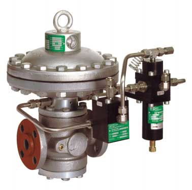
MANUALE TECNICO MT050                                   TECHNICAL MANUAL MT050

REFLUX 819

                                                R14/A

                                                                                 204/A

  PRESSIONE D’ENTRATA      PRESSIONE D’USCITA           ALIMENTAZIONE PILOTA         MOTORIZZAZIONE
  INLET PRESSURE           OUTLET PRESSURE              PILOT FEED                   MOTORIZATION

     Edizione Marzo 2000                                              Issue March 2000
                                                 2
MANUALE TECNICO MT050 TECHNICAL MANUAL MT050
INDICE INDEX
1.0 INTRODUZIONE PAGINA 4 1. INTRODUCTION PAGE 4
1.1 PRINCIPALI CARATTERISTICHE 4 1.1 MAIN SPECIFICATIONS 4
1.2 FUNZIONAMENTO 4 1.2 OPERATION 4
1.2.1 REGOLATORE PILOTA 204/A +R14/A 4 1.2.1 REGULATOR WITH PILOT 204/A+R14/A 4
1.3 MOLLE DI TARATURA 7 1.3 SETTING SPRINGS 7
2.0 INSTALLAZIONE 8 2.0 INSTALLATION 8
2.1 GENERALITA’ 8 2.1 GENERAL 8
3.0 ACCESSORI 11 3.0 ACCESSORIES 11
3.1 VALVOLA DI SFIORO 11 3.1 RELIEF VALVE 11
3.1.1 INSTALLAZIONE DIRETTA SULLA LINEA 12 3.1.1 DIRECT INSTALLATION ON THE LINE 12
3.1.2 INSTALLAZ. CON VALVOLA DI INTERCETTAZIONE 12 3.1.2 INSTALLATION WITH ON/OFF VALVE 12
3.2 ACCELERATORE 13 3.2 ACCELERATOR 13
4.0 MODULARITA’ 14 4.0 MODULARITY 14
4.1 VALVOLA DI BLOCCO INCORPORATA SB/82 14 4.1 INCORPORATED SB/82 SLAM-SHUT 14
4.2 FUNZIONAMENTO BLOCCO SB/82 15 4.2 SB/82 SLAM-SHUT OPERATION 15
4.3 MOLLE DI TARATURA BLOCCO SB/82 17 4.3 SB/82 SLAM-SHUT SETTING SPRINGS 17
4.4 MONITOR 18 4.4 MONITOR 18
4.4.1 MONITOR INCORPORATO 18 4.4.1 INCORPORATED MONITOR 18
4.4.2 MONITOR IN LINEA 19 4.4.2 IN-LINE MONITOR 19
5.0 MESSA IN SERVIZIO 20 5.0 START UP 20
5.1 GENERALITA’ 20 5.1 GENERAL 20
5.2 MESSA IN GAS, CONTROLLO TENUTA ESTERNA E 22 5.2 GAS INPUT, CONTROL OF EXTERNAL 22
TARATURA TIGHTNESS AND SETTING
5.3 MESSA IN SERVIZIO DEL REGOLATORE 23 5.3 COMMISSIONING THE REGULATOR 22
6.0 SISTEMI 24 6.0 SYSTEMS 24
6.1 MESSA IN SERVIZIO DEL REGOLATORE CON 24 6.1 COMMISSIONING THE REGULATOR 24
VALVOLA DI BLOCCO INCORPORATA WITH INCORPORATED SLAM-SHUT
6.2 MESSA IN SERVIZIO DEL REGOLATORE CON 28 6.2 COMMISSIONING THE REGULATOR WITH 28
MONITOR INCORPORATO PM/819 E VALVOLA INCORPORATED PM/819 MONITOR AND
ACCELERATRICE ACCELERATING VALVE
6.3 MESSA IN SERVIZIO DEL REGOLATORE PIU’ MONITOR 29 6.3 COMMISSIONING THE REGULATOR PLUS 29
IN LINEA REFLUX 819 CON VALVOLA DI BLOCCO SB/82 REFLUX 819 IN-LINE MONITOR WITH SB/82
SLAM-SHUT VALVE
7.0 ANOMALIE E INTERVENTI 33
7.0 TROUBLE-SHOOTING 33
7.1 REGOLATORE 33
7.2 BLOCCO SB/82 35 7.1 REGULATOR 33
7.2 SB/82 SLAM-SHUT 35
8.0 MANUTENZIONE 36
8.0 MAINTENANCE 36
8.1 GENERALITA’ 36
8.2 PROCEDURA DI MANUTENZIONE DEL REGOLATORE 37 8.1 GENERAL 36
REFLUX 819 8.2 REFLUX 819 REGULATOR MAINTENANCE 37
8.3 PROCEDURA DI MANUTENZIONE DEL 46 PROCEDURE
MONITOR PM/819 8.3 MONITOR PM/819 MAINTENANCE PROCEDURE 46
8.4 PROCEDURA DI MANUTENZIONE DEL SILENZIATORE DB/819 50 8.4 DB/819 SILENCER MAINTENANCE PROCEDURE 50
8.5 PROCEDURA DI MANUTENZIONE DELLA VALVOLA DI 52 8.5 SB/82 SLAM-SHUT DEVICE MAINTENANCE 52
BLOCCO SB/82 PROCEDURE
9.0 PESO DEI COMPONENTI 56 9.0 WEIGHT OF THE COMPONENTS 56
9.1 PESO DEI COMPONENTI IN KG 56 9.1 WEIGHT OF THE COMPONENTS IN KG 56
10.0 LISTA DEI RICAMBI 57 10.0 LIST OF RECOMMENDED SPARES 57
3MANUALE TECNICO MT050 TECHNICAL MANUAL MT050
1.0 INTRODUZIONE 1.0 INTRODUCTION
Scopo di questo manuale è di fornire informazioni The scope of this manual is to provide essential in-
essenziali per l'installazione, la messa in servizio, lo formation for the, commissioning, disassembly, re-
smontaggio, il rimontaggio e la manutenzione dei rego- assembly and maintenance of the REFLUX 819 regula-
latori REFLUX 819. tor.
Si ritiene inoltre opportuno fornire in questa sede una At the same time we consider it appropriate to provide
breve illustrazione delle caratteristiche principali del a brief illustration of the main features of the regulator
regolatore e dei suoi accessori. and its accessories.
1.1 PRINCIPALI CARATTERISTICHE 1.1 MAIN SPECIFICATIONS
Il regolatore di pressione REFLUX 819 è un regolatore The REFLUX 819 pressure regulator is a regulator for
per media e alta pressione. medium and high pressures.
Il REFLUX 819 è un regolatore normalmente chiuso e The REFLUX 819 regulator is normally closed and, as a
conseguentemente chiude in caso di: result, closes in the event of:
- rottura della membrana principale; - rupture of the main diaphragm;
- rottura della membrana del pilota; - rupture of the pilot diaphragm;
- mancanza di alimentazione del circuito pilota. - no feed in the pilot circuit.
Le caratteristiche principali di questo regolatore sono: The main specifications of this regulator are:
• Pressione di progetto: fino 100 bar; • Design pressure: up to 100 bar;
• Temperatura operativa: -10 °C ÷ + 50 °C (a richiesta • Working temperature range: -10 °C ÷ +50 °C (higher
temperature superiori o inferiori); or lower temperatures on request);
• Temperatura ambiente: -20 °C ÷ + 60 °C; • Ambient temperature: -20 °C ÷ + 60 °C;
• Campo della pressione di entrata bpe: 0,5 ÷ 85 bar • Inlet pressure range bpe: 0.5 ÷ 85 bar
• Campo di regolazione possibile Wh: • Regulating range possible Wh: 0.3 ÷ 60 bar (depen-
0,3 ÷ 60 bar (in funzione del pilota installato); ding on the pilot installed);
• Pressione differenziale minima 0,5 bar; • Minimum differential pressure: 0.5 bar;
• Classe di precisione RG: fino a 1; • Precision class RG: up to 1;
• Classe di pressione di chiusura SG: fino a 3. • Closing pressure class SG: up to 3.
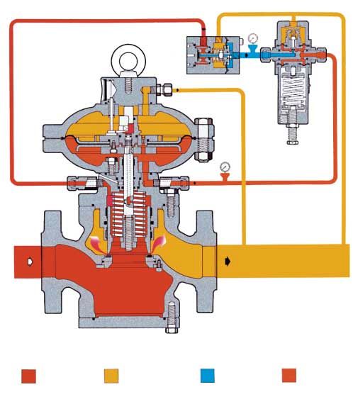
1.2 FUNZIONAMENTO 1.2 OPERATION
1.2.1 REGOLATORE CON PILOTA 204/A + R14/A 1.2.1 REGULATOR WITH PILOT 204/A + R14/A
(FIG. 1) (FIG. 1)
In assenza di pressione l'otturatore 5 è mantenuto in In the absence of pressure, the obturator 5 is maintained
posizione di chiusura dalla molla 54, e poggia sulla in the closed position by the spring 54, and rests on the
guarnizione armata 7 (fig. 1). La pressione di monte, reinforced gasket 7 (fig. 1). The upstream pressure, even
anche se variabile, non modifica questa posizione, in if variable, does not change this position as the obtura-
quanto l'otturatore è completamente bilanciato e quindi tor is completely balanced and is therefore subject to
soggetto a pressioni uguali anche se di sezione diversa. equal pressures, even if the sections are different.
Anche lo stelo 6 si trova tra due pressioni uguali poiché The rod 6 is also between two equal pressures as the
la pressione di monte, attraverso il foro A, viene porta- pressure upstream is also conveyed to the chamber C
ta anche nella camera C. through the hole A.
L'otturatore è comandato dalla membrana 50, sulla The obturator is controlled by the diaphragm 50 on
quale agiscono le seguenti forze: which the following forces act:
• verso il basso: il carico della molla 54, la spinta deri- • downwards: the load of the spring 54, the thrust
vante dalla pressione regolata Pa nella camera D e il deriving from the regulated pressure Pa in the cham-
peso dell'equipaggio mobile; ber D and the weight of the mobile assembly;
• verso l'alto: la spinta derivante dalla pressione di moto- • upwards: the thrust deriving from the motorisation
rizzazione Pm nella camera E, alimentata dal pilota. pressure Pm in the chamber E, supplied by the pilot.
4MANUALE TECNICO MT050 TECHNICAL MANUAL MT050
Collegamenti a cura del
N° di riferimento per i collegamenti
cliente
Ref. No. for the connections
Connections to be made
by the customer
3
1
1 3
Fig. 1
La pressione di motorizzazione è ottenuta prelevando The motorisation pressure is obtained by drawing gas
gas dal regolatore alla pressione di monte. Il gas viene from gas the regulator at the upstream pressure. The
filtrato attraverso il filtro 13 e subisce una prima decom- gas is filtered through the filter 13 and is subjected to
pressione nel preriduttore R14/A (fig. 2) composto initial decompression in the preregulator R14/A (fig. 2)
essenzialmente da un otturatore 5, da una molla 12 e da composed essentially of an obturator 5, a spring 12
una membrana 10 fino ad un valore Pep che dipende and a diaphragm 10 to a value, Pep, which depends on
dalla pressione di taratura del regolatore. Dalla camera the pressure set-point of the regulator. The pressure,
G la pressione Pep passa quindi nel pilota 204/A che Pep, then passes from the chamber G through the hole
regola tramite l'otturatore 17 fino al valore Pm di immis- F in the 204/A pilot which adjusts it by means of the
sione nella testata del regolatore. La regolazione di Pm obturator 17 until the inlet value, Pm, in the head of the
si ottiene dal confronto tra la forza esercitata dalla molla regulator. The regulation of Pm is obtained by the com-
di taratura 22 del pilota e l'azione della pressione rego- parison of the force exerted by the setting spring 22 of
lata Pa agente nella camera B sulla membrana 16. the pilot and the action of the regulated pressure, Pa,
La modifica della taratura viene effettuata ruotando la acting in the chamber B on the diaphragm 16.
vite di regolazione 10; una rotazione in senso orario The set-point can be changed by turning the adjust-
provoca un aumento della Pm e quindi della pressione ment screw 10; clockwise rotation increases Pm and
regolata Pa; viceversa per una rotazione in senso antio- therefore the regulated pressure, Pa; the opposite
rario. Se per esempio, durante il funzionamento c'è una occurs when the ring is turned anticlockwise. If, for
diminuzione di pressione di valle Pa (a causa dell'au- example, the downstream pressure, Pa, drops during
mento della portata richiesta o della diminuzione della operation (because of an increase in the requested flow
pressione di monte) si ha uno squilibrio nell'equipaggio rate or a drop in the upstream pressure) an imbalance
mobile 15 del pilota, che si sposta provocando un occurs in the mobile assembly 15 of the pilot, which is
aumento dell'apertura dell'otturatore 17. Aumenta di displaced to increase the opening of the obturator 17.
conseguenza anche il valore della pressione di motoriz- As a result, the motorisation pressure value, Pm,
zazione Pm, che agendo nella camera E al di sotto della increases and, by acting in the chamber E under the
membrana 50 (fig. 1) determina uno spostamento diaphragm 50 (fig. 1), causes the obturator 5 to move
verso l'alto dell'otturatore 5 e quindi l'aumento dell'a- upwards and therefore an increase in the opening of the
pertura del regolatore fino a ripristinare il valore presta- regulator until the set-point of the regulated pressure is
bilito della pressione regolata. restored.
5MANUALE TECNICO MT050 TECHNICAL MANUAL MT050
Viceversa, quando la pressione regolata inizia ad Vice versa, when the regulated pressure begins to
aumentare, la forza che essa esercita sulla membrana increase, the force it exerts on the diaphragm 16 of the
16 del pilota sposta l'equipaggio mobile 15 portando pilot moves the mobile assembly 15 displacing the
l'otturatore 17 verso la posizione di chiusura. La pres- obturator 17, towards the closed position. The pressu-
sione Pm quindi diminuisce a causa del travaso tra le re, Pm, then drops because of the transfer between the
camere E e D attraverso l'orifizio 21, e la forza esercita- chambers E and D through the orifice 21, and the force
ta dalla molla 54 provoca lo spostamento dell'otturato- exerted by the spring 54 causes the downward dis-
re 5 verso il basso, facendo così ritornare la pressione placement of the obturator 5, to restore the regulated
regolata al valore prestabilito. In condizioni di normale pressure to the set-point. In normal working condi-
esercizio l'otturatore 17 del pilota si posiziona in modo tions, the obturator 17 of the pilot positions itself so
che il valore della pressione di motorizzazione Pm sia that the motorisation pressure value, Pm, is such as to
tale da mantenere il valore della pressione di valle Pa maintain the downstream pressure value, Pa, around
attorno al valore prescelto. the set-point.
Fig. 2
6MANUALE TECNICO MT050 TECHNICAL MANUAL MT050
1.3 Molle di taratura 1.3 Setting springs
Il regolatore REFLUX 819 utilizza i piloti 204/A e 205/A. The REFLUX 819 regulator uses the 204/A and 205/A
I campi di regolazione dei diversi piloti sono riportati pilots. The regulation range of the different pilots is
nelle tabelle seguenti. given in the tables below.
Tab. 1 Pilota 204/A, 204/A/1 Tab. 1 Pilot 204/A, 204/A1
Codice Colore De Lo d i it Campo di taratura in bar
Code Colour Setting range in bar
1 2701260 BIANCO/WHITE 3.5 7.5 7.5 0.3 ÷ 1.2
2 2701530 GIALLO/YELLOW 4 7 7 0.7 ÷ 2.8
3 2702070 ARANCIO/ORANGE 5 7 7 1.5 ÷ 7
4 2702450 ROSSO/RED 35 60 6 7 7 4 ÷ 14
5 2702815 VERDE/GREEN 7 7 7 8 ÷ 20
6 2703220 NERO/BLACK 8 6 6 15 ÷ 33
7 2703420 BLU/BLEU 8.5 6 6 22 ÷ 43
Tab. 2 Pilota 205/A Table 2 Pilot 205/A
Codice Colore Campo di taratura in bar
Code Colour De Lo d i it
Setting range in bar
4 2702820 BLU/BLUE 7 7 9 20 ÷ 35
5 2703045 MARRONE/BROWN 35 100 7.5 7.5 9.5 30 ÷ 43
6 2703224 GRIGIO/GREY 8 7.5 9.5 40 ÷ 60
De = Ø esterno d = Ø filo i = n. spire utili Lo = Lunghezza molla it = n. spire totali
De = external diameter d = wire diameter i = active coils Lo = Spring length it = total coils
7MANUALE TECNICO MT050 TECHNICAL MANUAL MT050
2.0 INSTALLAZIONE 2.0 INSTALLATION
2.1 GENERALITÀ 2.1 GENERAL
Prima di installare il regolatore è necessario assicurarsi che: Before installing the regulator you must ensure that:
a) il regolatore sia inseribile nello spazio previsto e sia a) the regulator can be inserted into the space pro-
sufficientemente agibile per le successive operazio- vided and that it is sufficiently accessible for sub-
ni di manutenzione; sequent maintenance operations;
b) le tubazioni di monte e di valle siano al medesimo b) the piping upstream and downstream are at the
livello e in grado di sopportare il peso del regolatore; same level and able to support the weight of the
c) le flange di entrata/uscita della tubazione siano regulator;
parallele; c) the inlet/outlet flanges on the piping are parallel;
d) le flange di entrata/uscita del regolatore siano pulite d) the inlet/outlet flanges on the regulator are clean
e il regolatore stesso non abbia subito danni duran- and the regulator itself has not been damaged
te il trasporto; during transport;
e) la tubazione a monte sia stata pulita eliminando le e) the piping upstream has been cleaned with the
impurità residue quali scorie di saldatura, sabbia, removal of residual impurities such as welding slag,
residui di vernice, acqua, ecc. sand, paint residues, water, etc.
La disposizione normalmente prescritta è: The normally recommended set-ups are:
Fig. 3 (Regolatore standard) Fig. 3 (Standard Regulator)
8MANUALE TECNICO MT050 TECHNICAL MANUAL MT050
TAB. 3 COLLEGAMENTO APPARECCHIATURE TAB. 3 CONNECTING THE APPARATUSES
INSTALLAZIONE IN LINEA IN-LINE INSTALLATION
Regolatore Presa d’impulso Manometro di controllo
Regulator Sensing line Control pressure gauge
Collegamento a valle Rubinetto di sfiato
Downstream connection Bleed cock
Valvola di intercettazione
On/Off valve
INSTALLAZIONE A SQUADRA INSTALLATION AT RIGHT ANGLES
Presa d’impulso
Sensing line
Regolatore
Regulator
Rubinetto di sfiato
Bleed cock
Collegamento a valle
Downstream connection
Manometro di
controllo
Control pressure
gauge
Valvola di intercettazione
On/Off valve
9MANUALE TECNICO MT050 TECHNICAL MANUAL MT050
TAB. 4 PARTICOLARE PRESA MULTIPLA CON TAB. 4 DETAIL OF THE MULTIPLE TAKE-OFF
I NUMERI DI RIFERIMENTO PRESE DI WITH SENSING LINE REFERENCE
IMPULSO NUMBERS
1 e 2 Collegare alle teste dei regolatori 1 and 2 Connect to regulators heads
3 e 4 Collegare ai piloti 3 and 4 Connect to pilots
5 e 6 Collegare all’acceleratore e al blocco 5 and 6 Connect to accelerator and slam-shut
Il regolatore va installato sulla linea orientando la frec- The regulator must be installed in the line with the
cia sul corpo nel senso del flusso del gas. arrow on the body pointing in the gas flow direction.
Per ottenere una buona regolazione è indispensabile che For good regulation it is indispensable that the position
la posizione delle prese di pressione di valle e la velocità of the downstream pressure take-offs and the speed of
del gas nel punto di presa rispettino i valori indicati nelle the gas at the take-off point respect the values given in
tabelle 3 e 4 (posizionamento) e 5 (velocità). tables 3 and 4 (positioning) and 5 (speed).
Allo scopo di evitare il raccogliersi di impurità e con- The following are recommended so as to prevent the
dense nei tubi delle prese di pressione si consiglia: accumulation of impurities and condensate in the lines
a) che i tubi stessi siano sempre in discesa verso l’at- of the pressure take-offs:
tacco della tubazione di valle con una pendenza a) the lines themselves must slope down towards the
all’incirca del 5-10%; downstream piping with a slope of about 5-10%;
b) che gli attacchi della tubazione siano sempre salda- b) the connectors on the piping must always be welded
ti sulla parte superiore della tubazione stessa e che on the top of the piping itself and there must be no
il foro sulla tubazione non presenti bave o sporgen- burr or inward protrusions in the hole in the piping.
ze verso l’interno.
NB. SI RACCOMANDA DI NON INTERPORRE NB. WE RECOMMEND NOT TO PUT ON/OFF VALVES
VALVOLE DI INTERCETTAZIONE SULLE PRESE DI ON THE IMPULSE TAKE-OFFS.
IMPULSO.
TAB. 5 TAB. 5
Nella tubazione a valle del regolatore la velocità The speed of the gas must not exceed the following
del gas non deve superare i seguenti valori: values in the piping downstream from the regulator:
Vmax= 30 m/s per Pa > 5 bar Vmax= 30 m/s for Pa > 5 bar
Vmax= 25 m/s per 0,5 < Pa < 5 bar Vmax= 25 m/s for 0,5 < Pa < 5 bar
10MANUALE TECNICO MT050 TECHNICAL MANUAL MT050
3.0 ACCESSORI 3.0 ACCESSORIES
3.1 VALVOLA DI SFIORO 3.1 RELIEF VALVE
La valvola di sfioro è un dispositivo di sicurezza che The relief valve is a safety device which releases a cer-
provvede a scaricare all’esterno una certa quantità di tain quantity of gas to the exterior when the pressure at
gas quando la pressione nel punto di controllo supera the control point exceeds the set-point as a result of
quella di taratura a causa di eventi non duraturi, quali short-lasting events such as, for example, the very fast
per esempio, la chiusura di valvole di intercettazione in closing of the on/off valves and/or overheating of the
un tempo molto ridotto e/o un surriscaldamento del gas gas with zero flow rate demand. The release of the gas
con portata richiesta nulla. Lo scarico del gas all’ester- to the exterior can, for example, delay or block inter-
no può, per esempio ritardare o evitare l’intervento del vention of the slam-shut valve for transitory reasons
dispositivo di blocco per cause transitorie derivanti da deriving from damage to the regulator.
danni al regolatore. Obviously the quantity of gas released depends on the
Ovviamente la quantità di gas scaricata dipende dall’en- extent of the overpressure with respect to the set-point.
tità della sovrapressione rispetto alla taratura. I diversi The different models of relief valve available are all
modelli di valvole di sfioro disponibili si basano tutti based on the same operating principle which is illus-
sullo stesso principio di funzionamento, che viene in trated below with reference to the valve VS/AM 56 (fig. 4).
seguito illustrato facendo riferimento alla valvola It is based on the contrast between the thrust on the
VS/AM 56 (fig. 4). diaphragm 24 deriving from the pressure of the gas to
Esso si fonda sul confronto tra la spinta sulla membrana control and the thrust from the setting spring 20. The
24 derivante dalla pressione del gas da controllare e la weight of the mobile assembly, the static thrust and the
spinta derivante dalla molla di taratura 20. In questo con- residual dynamic thrust on the obturator 4 also contri-
fronto intervengono il peso dell’equipaggio mobile, le spin- bute to this contrast.
te statiche e quelle dinamiche residue sull’otturatore 4. When the thrust deriving from the pressure of the gas
Quando la spinta derivante dalla pressione del gas supera exceeds that of the setting spring, the obturator 4 is
quella della molla di taratura, l’otturatore 4 viene sollevato raised and a certain quantity of gas is released as a
con conseguente scarico di una certa quantità di gas. result.
Non appena la pressione scende al di sotto del valore di As soon as the pressure drops below the set-point, the
taratura, l’otturatore ritorna in posizione di chiusura. Il obturator returns to the closed position. Proceed as
controllo e la registrazione dell’intervento della valvola indicated below to control and adjust intervention of
di sfioro può essere eseguito seguendo le procedure di the relief valve.
seguito indicate.
Fig. 4
11MANUALE TECNICO MT050 TECHNICAL MANUAL MT050
3.1.1 INSTALLAZIONE DIRETTA SULLA LINEA 3.1.1 DIRECT INSTALLATION ON THE LINE
(FIG. 5) (FIG. 5)
Quando la valvola di sfioro è montata direttamente sulla When the relief valve is fitted directly in the line without,
linea, senza cioè l’interposizione di una valvola di inter- that is, the interposition of an on/off valve, we recom-
cettazione, si consiglia di procedere come indicato di mend proceeding as follows:
seguito:
1)Assicurarsi che la valvola di intercettazione di valle V2 1)Ensure that the downstream on/off valve V2 and the
e il rubinetto di sfiato 6 siano chiusi; bleed cock 6 are closed;
2)Aumentare la pressione nel tronco di valle fino al valo- 2)Increase the pressure in the downstream section to
re previsto di intervento in uno dei seguenti modi: the value envisaged for intervention in one of the fol-
- se la molla montata sul pilota lo consente (ved. tab. lowing ways:
1-2), incrementare la taratura del pilota stesso fino a - if the spring fitted on the pilot itself until the desi-
raggiungere il valore desiderato; der value is obtained;
- collegare al rubinetto 6 una pressione ausiliaria con- - connect a controlled auxiliary pressure to the cock
trollata e stabilizzarla al valore desiderato; 6 and stabilize it at the desidered value;
3)Verificare l’intervento della valvola di sfioro ed even- 3)Check intervention of the relief valve and adjust it if
tualmente registrarlo ruotando opportunamente il necessary by turning the adjustment plug 13 appro-
tappo di regolazione 13 (in senso orario per aumentare priately (clockwise to increase the set-point, anti-
la taratura, e viceversa per diminuirla). clockwise to reduce it).
Fig. 5 Fig. 6
3.1.2 INSTALLAZIONE CON VALVOLA DI 3.1.2 INSTALLATION WITH ON/OFF VALVE
INTERCETTAZIONE (FIG. 6) (FIG. 6)
1)Chiudere la valvola di intercettazione 16; 1) Close the on/off valve 16;
2)Collegare alla presa 17 una pressione ausiliaria con- 2)Connect a controlled auxiliary pressure to the take-
trollata e aumentarla lentamente fino al valore previsto off 17 and increase it slowly to the envisaged inter-
di intervento; vention value;
3)Verificare l’intervento della valvola di sfioro ed even- 3)Check the intervention of the relief valve and adjust it
tualmente registrarlo ruotando opportunamente il if necessary by turning the adjustment plug 13 app-
tappo 13 di regolazione interna 17 (in senso orario per ropriately (clockwise to increase the set-point, anti-
aumentare la taratura, e viceversa per diminuirla). clockwise to reduce it).
12MANUALE TECNICO MT050 TECHNICAL MANUAL MT050
3.2 ACCELERATORE 3.2 ACCELERATOR
Nel caso in cui si impieghi come monitor il regolatore With the REFLUX 819 regulator used a monitor or the
REFLUX 819 o il monitor incorporato PM/819, per incorporated PM/819 monitor an accelerator is instal-
accelerarne l'intervento in caso di inconvenienti al rego- led to accelerate its action in the event of failure of the
latore di servizio, si provvede ad installare un accelera- service regulator (fig. 7).
tore (fig. 7) sul riduttore monitor. On the basis of a pressure signal from down-line, this
Questo apparecchio, in funzione di un segnale di pres- device discharges the gas enclosed in the monitor's
sione di valle, provvede a scaricare all'atmosfera il gas motorization chamber into the atmosphere, thereby
racchiuso nella camera di motorizzazione del monitor permitting rapid intervention. The set point of the acce-
consentendone così un più rapido intervento. lerator must obviously be higher than that of the moni-
Ovviamente la taratura dell'acceleratore deve essere più tor.
alta di quella del monitor. Setting is made by turning the adjustment screw 17,
La taratura viene effettuata ruotando la vite di rego- clockwise to increase the value, anticlockwise to redu-
lazione 17, in senso orario per aumentare il valore, in ce it.
senso antiorario per diminuirlo. M/A range of intervention Who: 0,3 ÷ 43 bar
M/A campo di intervento Who: 0,3 ÷ 43 bar.
Acceleratore M/A-Accelerator M/A
Fig. 7
13MANUALE TECNICO MT050 TECHNICAL MANUAL MT050
4.0 MODULARITÀ 4.0 MODULARITY
La concezione di tipo modulare dei regolatori della serie The modular-type conception of REFLUX 819 series regu-
REFLUX 819 assicura la possibilità di applicare il regola- lators means that it is also possible to fit either the emer-
tore di emergenza monitor PM/819 o la valvola di blocco gency monitor regulator PM/819 or the slam-shut incor-
allo stesso corpo senza modificarne lo scartamento, porated with the body itself even after the installation of the
anche in tempi successivi all'installazione del regolatore. regulator, without having to alter any dimensions.
Furthermore, the regulator can be adapted for operation as
an in-line monitor by installing a special device.
4.1 VALVOLA DI BLOCCO INCORPORATA SB/82
4.1 INCORPORATED SB/82 SLAM-SHUT VALVE
E' un dispositivo (fig. 8) che blocca immediatamente il
flusso del gas se, a causa di qualche guasto, la pressio- This is a device (fig. 8) which immediately blocks the
ne di valle raggiunge il valore prefissato per il suo inter- gas flow if, following some kind of failure, the down-
vento, oppure se la si aziona manualmente. stream pressure reaches the set-point for its interven-
Per il regolatore di pressione REFLUX 819 esiste la pos- tion, or is operated manually.
sibilità di avere la valvola SB/82 incorporata sia sul On the REFLUX 819 regulator, it is possible to have the
regolatore di servizio come pure su quello con funzione SB/82 slam-shut incorporated both with the service
di monitor in linea. regulator or on the one functioning as in-line monitor.
Le principali caratteristiche di tale dispositivo di blocco sono: The main characteristics of the slam-shut device are:
• intervento per incremento e/o diminuzione della • intervention with pressure increase and/or decrease;
pressione; • design pressure: 93,8 bar for all the components;
• pressione di progetto: 93,8 bar per tutti i componenti; • precision (AG): ± 1% of the pressure set-point for
• precisione (AG): ± 1% sul valore della pressione di pressure increases; ± 5% for pressure drops;
taratura per aumenti di pressione; ± 5% per diminu- • manual resetting with internal bypass operated by
zione di pressione; the resetting lever.
• riarmo manuale con by-pass interno azionato dalla
leva di riarmo.
Preriscaldo gas circuito pilota
Heating system for pilot system
3
Collegamento a cura del cliente
Connection to be made by the customer
Collegamento senza scambiatori per piloti
Connection without heat exchanger in
the pilot supply
1
N° di riferimento per i collegamenti
Ref. No. for the connections
5
3
1
5
Fig. 8
14MANUALE TECNICO MT050 TECHNICAL MANUAL MT050
4.2 FUNZIONAMENTO BLOCCO SB/82 4.2 SB/82 SLAM-SHUT OPERATION
Il dispositivo di blocco SB/82 (vedi fig. 9) è costituito da The SB/82 slam-shut device (see fig. 9) consists of an
un otturatore A, da un complesso di leverismi per lo obturator A, a releasing lever system, a control head B
sgancio, da una testa di comando B e da un sistema di and a resetting system which is controlled manually by
riarmo comandato manualmente tramite la leva C. La the lever C. The pressure in the circuit to control acts
pressione del circuito da controllare agisce sulla testa di on the diaphragm in the control head B. This diaph-
comando B, a membrana; questa membrana, solidale ragm, which is integral with a control rod D, receives a
ad un'asta di comando D riceve una forza antagonista counter-force by means of the minimum pressure
tramite delle molle di minima 17 e di massima 11 pres- springs 17 and the maximum pressure springs 11, set
sione, tarate ai valori prefissati. at the preset values .
Il movimento di traslazione di questa asta provoca lo The translation movement of this rod provokes the
spostamento della leva L che comanda lo sgancio di displacement of the lever L which controls the release
tutto il sistema mobile liberando l'otturatore che si of the entire mobile system and frees the obturator
porta in chiusura per azione della molla 48. which is closed by the action of the spring 48.
Per riarmare il dispositivo si agisce sulla leva C la quale To reset the device, operate the lever C. This opens an
nel primo tratto della corsa apre un by-pass interno che internal bypass in the first part of its stroke. This leads
consente l'invaso della zona a valle e permette così di to filling of the downstream zone and balances the
equilibrare la pressione sull'otturatore; successivamen- pressure on the obturator. Then, complete resetting of
te, nella seconda parte della corsa della stessa leva C, si the entire mobile system is obtained in the second part
ottiene il riaggancio vero e proprio di tutto il sistema of the stroke of the lever C. Releasing can also be car-
mobile. Lo sgancio può essere comandato anche ried out manually by means of the button 101.
manualmente tramite il pulsante 101.
Fig. 9
15MANUALE TECNICO MT050 TECHNICAL MANUAL MT050
DISPOSITIVO DI COMANDO CONTROL DEVICES
TESTATE DI COMANDO SLAM-SHUT CONTROL HEADS
16MANUALE TECNICO MT050 TECHNICAL MANUAL MT050
4.3 TAB. 6 MOLLE DI TARATURA BLOCCO SB/82 4.3 TAB. 6 SB/82 SLAM-SHUT SETTING SPRINGS
CAMPO DI TARATURA in bar
SETTING RANGE in bar
Caratteristiche molla 102 106 102 106 103 107 103 107 104 108 104- 105 109 105-
Characteristics spring 108 109
Codice Colore De Lo d i it bar/min bar/max bar/min bar/max bar/min bar/max bar/min bar/max
Code Colour
BIANCO/
1 2700565 1 12 14
WHITE
GIALLO/
2 2700675 1,3 13 15 0,04 ÷ 0,1 0,2 ÷ 0,5
YELLOW
ARANCIO/
3 2700820 1,5 11 13 0,07 ÷ 0,2 0,4 ÷ 1,2
ORANGE
10 40
ROSSO/
4 2700910 1,7 11 13 0,15 ÷ 0,3 0,8 ÷ 2 1,6 ÷ 4 3,2 ÷ 8
RED
VERDE/
5 2701035 2 11 13 0,25 ÷ 0,45 1,4 ÷ 2,7 2,8 ÷ 5,4 5,6 ÷ 10,8
GREEN
NERO/
6 2701140 2,3 10 12 0,40 ÷ 0,7 2,3 ÷ 4 4,6 ÷ 8 9,2 ÷ 16
BLACK
ARANCIO/
7 2700790 2,5 8 10 0,1 ÷ 0,25
ORANGE
ROSSO/
8 2701010 3 7 9 0,2 ÷ 0,6 1÷3
RED
VERDE/
9 2701225 3,5 6 8 0,5 ÷ 1 2÷5
GREEN
NERO/
10 2701475 25 55 4 6 8 0,7 ÷ 1,6 3,5 ÷ 8 7 ÷ 15 14 ÷ 30
BLACK
VIOLA/
11 2701740 4,5 6 8 1,3 ÷ 2,15 6 ÷ 10 12 ÷ 20 24 ÷ 30
VIOLET
AZZURRO/
12 2702015 5 6 8 2 ÷ 3,25 9 ÷ 14 18 ÷ 28 36 ÷ 56
AZURE
GRIGIO/
13 2702245 5,5 6 8 3,5 ÷ 5 13 ÷ 22 26 ÷ 44 52 ÷ 88
GREY
MARRONE/
14 2700680 2,3 6 8
BROWN
ROS./NERO
15 2700830 2,5 5,5 7,5
RED/BLACK
BIAN./GIAL.
16 2700920 2,7 5,5 7,5
WHITE/YEL.
BIAN./ARAN.
17 2701040 3 5,5 7,5
WHI./ORAN.
BIANCO/
18 2701260 3,5 5,5 7,5 0,2 ÷ 0,5 0,2 ÷ 0,5
WHITE
GIALLO/
19 2701530 35 60 4 5 7 0,45 ÷ 1,1 0,45 ÷ 1,1 2÷5 2÷5
YELLOW
GIAL./NERO
20 2701790 4,5 4,5 6,5 0,7 ÷ 1,7 0,7 ÷ 1,7 3,5 ÷ 8,5 3,5 ÷ 8,5
YEL./BLACK
ARANCIO/
21 2702070 5 5 7 0,9 ÷ 2 0,9 ÷ 2 5 ÷ 10,5 5 ÷ 10,5
ORANGE
BIAN./ROS.
22 2702280 5,5 5 6,5 1,5 ÷ 3 1,5 ÷ 3 7,5 ÷ 15 7,5 ÷ 15 15 ÷ 30 30 ÷ 60
WHI./RED
ROSSO/
23 2702450 6 5 7 2,2 ÷ 3,5 2,2 ÷ 3,5 10,5 ÷ 16,5 10,5 ÷ 16,5 21 ÷ 33 42 ÷ 66
RED
VERDE/
24 2702650 6,5 5 7 3,5 ÷ 5 3,5 ÷ 5 15 ÷ 22 15 ÷ 22 30 ÷ 44 60 ÷ 88
GREEN
De = Ø esterno d = Ø filo i = n. spire utili Lo = Lunghezza molla libera it = n. spire totali
De = external diameter d = wire diameter i = active coils Lo = Spring length it = total coils
17MANUALE TECNICO MT050 TECHNICAL MANUAL MT050
4.4 MONITOR 4.4 MONITOR
Il monitor è un regolatore di emergenza che entra in The monitor is an emergency regulator which comes
funzione in sostituzione del regolatore di servizio se per into operation to replace the service regulator if for any
qualche ragione quest'ultimo consente alla pressione di reason the latter permits the down-line pressure to rise
valle di salire fino a raggiungere il valore prefissato per up to the value set for its intervention.
il suo intervento.
4.4.1 MONITOR INCORPORATO 4.4.1 INCORPORATED MONITOR
Questo dispositivo di emergenza (fig. 10) è fissato This emergency device (fig. 10) is fixed directly on the
direttamente al corpo del regolatore di servizio. In que- body of the service regulator. In this way, the two pres-
sto modo i due regolatori di pressione utilizzano lo sure regulators use the same valve body but:
stesso corpo valvola ma:
- they are governed by two distinct pilots and two
- sono governati da due piloti distinti e da servomoto-
ri indipendenti; independent servomotors;
- lavorano su sedi valvola indipendenti. - they work on independent valve seats.
3
1
6
3 4
1 2
4
6
2
Preriscaldo gas circuito pilota
Heating system for pilot system
Collegamento a cura del cliente
Connection to be made by the customer
Collegamento senza scambiatori per piloti
Connection without heat exchanger in the pilot supply
N° di riferimento per i collegamenti
Ref. No. for the connections
... + Monitor incorporato PM/819 - PM/819 incorporated monitor
Fig. 10
18MANUALE TECNICO MT050 TECHNICAL MANUAL MT050
4.4.2 MONITOR IN LINEA 4.4.2 IN-LINE MONITOR
In questa applicazione il regolatore di emergenza è With this kind of application, the emergency regulator
installato a monte di quello di servizio (fig. 11). is installed up-line from the service one (fig. 11).
3
4 5
2 1
5
3 4
1 2
3
4
5
2 1
5 6
4 3
1 2
6
Preriscaldo gas circuito pilota
Heating system for pilot system N° di riferimento per i collegamenti
Ref. No. for the connections
Collegamento a cura del cliente
Connection to be made by the customer
Collegamento senza scambiatori per piloti
Connection without heat exchanger in the pilot supply Fig. 11
19MANUALE TECNICO MT050 TECHNICAL MANUAL MT050
5.0 MESSA IN SERVIZIO 5.0 START UP
5.1 GENERALITÀ 5.1 GENERAL
Dopo l'installazione verificare che le valvole di intercet- After installation, check that the inlet/output on-off val-
tazione di entrata/uscita, l'eventuale by-pass e il rubi- ves, any bypass and the relief valves are closed.
netto di sfiato siano chiusi. Before starting up, checking is recommended to ascer-
Si raccomanda di verificare, prima della messa in servi- tain that the conditions of use are in conformity with
zio, che le condizioni di impiego siano conformi alle the specifications of the equipment. These specifica-
caratteristiche delle apparecchiature. Tali caratteristiche tions are recalled with the symbols on the plate fitted
sono richiamate con dei simboli sulle targhette di cui on every component.
ogni apparecchiatura è munita.
TARGHETTE APPARECCHIATURE APPARATUS SPECIFICATION PLATES
VICENZA VICENZA
ITALY ITALY
S.p.A. S.p.A.
PRERIDUTTORE PILOTA 204/A
R14/A PILOT
PRE-REGULATOR
N. Fab. Anno
N. Fab. Anno Reg. No Q90875 Year 3/99
Q90876 3/99
Reg. No Year Pzul bar Wh
85 0,3/43 bar
Pzul 85 bar Pe max bar
Wa 1,5/7 bar
Pa + 1,25/2,8 bar Pa + 1,25/2,8 bar
Press-uscita Alimentazione pilota
Oulet pressure Pilot valve supply
20MANUALE TECNICO MT050 TECHNICAL MANUAL MT050
Di seguito è riportato l’elenco dei simboli usati e il loro The list of symbols used and their meanings are listed
significato: below:
Pemax= massima pressione di funzionamento Pemx= maximum inlet operating pressure of the appa-
all’entrata dell’apparecchio ratus
bpe= campo di variabilità della pressione di entrata del bpe= range of variability of the inlet pressure of the
regolatore di pressione in condizioni di normale funzio- pressure regulator in normal operating conditions
namento Pzul= maximum pressure which can be supported by
Pzul= massima pressione che può essere sopportata in the structure of the body of the apparatus in safety con-
condizioni di sicurezza dalla struttura del corpo dell’appa- ditions
recchio Wa= range of setting of the pressure regulator/
Wa= campo di taratura del regolatore di pressione/ pilot/pre-regulator which can be obtained using the
pilota/preriduttore che può essere ottenuto usando i parts and the setting spring fitted at the moment of
particolari e la molla di taratura montati al momento del testing (without changing any components of the ap-
collaudo (non cambiando cioè alcun componente del- paratus, that is). In piloted regulators, the pilot is con-
l’apparecchio). Nei regolatori pilotati il pilota viene con- sidered as a separate apparatus with its own setting
siderato come apparecchiatura separata con proprio range Wa
campo di taratura Wa Wh= range of setting of the pressure regulator/pilot/
Wh= campo di taratura del regolatore di pressione/pilo- pre-regulator which can be obtained using the setting
ta/preriduttore che può essere ottenuto usando le molle springs indicated in the associated tables and also by
di taratura indicate nelle apposite tabelle ed eventual- changing some other part of the apparatus (reinforced
mente cambiando qualche altro particolare dell’appa- gasket, diaphragm etc.). In piloted regulators, the pilot
recchio (pastiglia armata, membrane, ecc.). Nei regola- is considered as a separate apparatus with its own set-
tori pilotati il pilota viene considerato come apparec- ting range Wh
chiatura separata con proprio campo di taratura Wh QmxPemin= maximum flow rate with minimum pres-
QmxPemin= portata massima con la pressione minima sure at the pressure regulator inlet
all’entrata del regolatore di pressione QmxPemx= maximum flow rate with maximum pres-
QmxPemax= portata massima con la pressione massi- sure at the pressure regulator inlet
ma all’ingresso del regolatore di pressione Cg= experimental coefficient of critical flow
Cg= coefficiente sperimentale di portata critica RG= regulation class
RG= classe di regolazione SG= closing pressure class
SG= classe di pressione di chiusura AG= intervention accuracy
AG= precisione di intervento Wao= range of operation for over pressure of slam-
Wao= campo di intervento per sovrapressione di valvo- shut, relief and safety valves and accelerators which
le di blocco, sfioro e di sicurezza e acceleratori che può can be obtained using the setting spring fitted at the
essere ottenuto usando la molla di taratura montata al moment of testing. In piloted regulators, the pilot is
momento del collaudo. Nelle valvole di sicurezza pilota- considered as a separate apparatus with its own setting
te il pilota viene considerato come apparecchiatura range Wao
separata con proprio campo di taratura Wao Who= range of operation for over pressure of slam-
Who= campo di intervento per sovrapressione di valvo- shut, relief and safety valves and accelerators which
le di blocco, sfioro e di sicurezza e acceleratori che può can be obtained using the setting springs indicated in
essere ottenuto usando le molle di taratura indicate the tables. In piloted safety valves, the pilot is conside-
nelle tabelle. Nelle valvole di sicurezza pilotata il pilota red as a separate apparatus with its own setting range
viene considerato come apparecchiatura separata con Who
proprio campo di taratura Who Wau= range of intervention for of slam-shut which can
Wau= campo di intervento per diminuzione di pressio- be obtained using the setting spring fitted at the
ne di valvole di blocco che può essere ottenuto usando moment of testing
la molla di taratura montata al momento del collaudo Whu= range of pressure decrease of slam-shut which
Whu= campo di intervento per diminuzione di pressio- an be obtained using the setting springs indicated in
ne di valvole di blocco che può essere ottenuto usando the tables.
le molle di taratura indicate nelle tabelle.
21MANUALE TECNICO MT050 TECHNICAL MANUAL MT050
5.2 MESSA IN GAS, CONTROLLO TENUTA 5.2 GAS INPUT, CONTROL OF EXTERNAL
ESTERNA E TARATURE TIGHTNESS AND SETTING
La tenuta esterna è garantita quando, cospargendo l’e- External tightness is guaranteed if no bubbles form
lemento in pressione con un mezzo schiumogeno, non when a foam medium is applied on the element under
si formano rigonfiamenti di bolle. pressure.
Il regolatore e le altre eventuali apparecchiature (valvo- The regulator and any other apparatuses (slam-shut,
la di blocco, monitor) vengono normalmente forniti già monitor) are normally supplied already set for the de-
tarati al valore richiesto. E’ peraltro possibile che per sired set-point. It is possible for various reasons
vari motivi (es. vibrazioni durante il trasporto), le tara- (e.g., vibration during transport) for the settings to be
ture possano subire modifiche, restando in ogni caso changed while remaining within the values permitted
comprese entro i valori consentiti dalle molle utilizzate. by the springs used.
Si consiglia quindi di verificare le tarature secondo le We therefore recommend checking the settings using
procedure di seguito illustrate. the procedures illustrated below.
Nelle tabelle 7 e 8 sono riportati i valori consigliati di Tables 7 and 8 give the recommended set-points for the
taratura delle apparecchiature previste nelle diverse apparatuses in the various installation arrangements.
filosofie impiantistiche. I dati di queste tabelle possono The figures in these tables can be useful both when
risultare utili sia in fase di verifica delle tarature esi- checking existing set-points and for modifying them
stenti, sia in caso di modifiche delle stesse che doves- should this become necessary later.
sero rendersi necessarie in tempi successivi. In installations consisting of two lines, we suggest
Per gli impianti composti da due linee, si suggerisce di commissioning one line at a time, starting from the one
procedere alla messa in servizio di una linea alla volta, with the lower set-point, known as the “reserve” line.
iniziando da quella con taratura inferiore cosiddetta “di The set-points of the apparatuses in this line will
riserva”. Per questa linea, i valori di taratura delle obviously deviate from those specified in the tables 7
apparecchiature si scosteranno ovviamente da quelli and 8.
indicati dalle tabelle 7 e 8.
Prima di procedere alla messa in servizio del regola- Before commissioning the regulator you must check
tore è necessario verificare che tutte le valvole di that all the on/off valves (inlet, outlet, any by-pass)
intercettazione (entrata, uscita, by-pass eventuale) are closed and that the gas is at a temperature which
siano chiuse e che il gas sia a temperatura tale da
will not lead to malfunction.
non generare disfunzioni.
22MANUALE TECNICO MT050 TECHNICAL MANUAL MT050
5.3 MESSA IN SERVIZIO DEL REGOLATORE 5.3 COMMISSIONING THE REGULATOR
(FIG.12) (FIG.12)
Nel caso sia presente sulla linea anche la valvola di sfio- If there is also a relief valve in the line, refer to par. 3.1
ro, fare riferimento al par. 3.1 per la sua verifica. to check it.
Fig. 12
Si procede quindi nel seguente modo: Proceeded as follows:
1) Aprire parzialmente il rubinetto di sfiato 6. 1) Partially open the bleed cock 6.
2) Aprire molto lentamente la valvola di intercettazione 2) Very slowly open the inlet on/off valve V1.
di entrata V1. 3) Check on the pressure gauge 5 that the pressure
3) Controllare, mediante il manometro 5, che la pres- does not exceed the maximum value permitted by
sione non superi il valore massimo consentito dalla
the setting spring fitted in the pilot 3. If necessary,
molla di taratura montata nel pilota 3. Eventualmente
sospendere l'operazione chiudendo V1 e diminuendo suspend the operation by closing V1 and completely
completamente il carico della molla ruotando in reducing the load on the spring by turning the adju-
senso antiorario la vite di regolazione 10. Riaprire stment screw 10 anticlockwise. Then slowly reopen
quindi lentamente la valvola V1. the valve V1.
4) Aggiustare, se necessario, la taratura ruotando 4) If necessary, adjust the setting by turning the adjust-
opportunamente la vite di regolazione 10. ment screw 10 appropriately.
5) Chiudere il rubinetto di sfiato 6 e verificare che la 5) Close the bleed cock 6 and check that the down-
pressione di valle, dopo una fase di incremento, si stream pressure, after increasing, settles at a value
stabilizzi, e ad un valore inferiore o uguale a quello lower or equal to that of closure of the pilot/regu-
proprio di chiusura dell'insieme pilota/regolatore. In
lator assembly. If it does not, remedy the causes of
caso contrario rimuovere le cause che generano la
the internal leakage.
perdita interna.
6) Con un mezzo schiumogeno controllare la tenuta di 6) Using a foaming agent, check the tightness of all the
tutte le giunzioni poste tra le valvole di intercettazio- joints between the on/off valves V1 and V2.
ne V1 e V2. 7) Very slowly open the downstream on/off valve V2
7) Aprire molto lentamente la valvola di intercettazione until the line is completely filled. If, at the beginning
di valle V2 fino ad ottenere il completo invaso della of this operation, the pressure in the line is much
condotta. Se all'inizio di questa operazione la pres- lower than the set-point, the opening of this valve
sione nella condotta è molto più bassa di quella di should be choked so as not to exceed the maximum
taratura sarà opportuno parzializzare l'apertura di flow rate value of the installation.
questa valvola in modo da non oltrepassare il valore
della portata massima dell'impianto.
23MANUALE TECNICO MT050 TECHNICAL MANUAL MT050
6.0 SISTEMI 6.0 SYSTEM
6.1 MESSA IN SERVIZIO DEL REGOLA- 6.1 COMMISSIONING THE REGULATOR WITH
TORE CON VALVOLA DI BLOCCO INCOR- INCORPORATED SLAM-SHUT (FIG. 13)
PORATA (FIG. 13)
Nel caso sia presente sulla linea anche la valvola di sfio- If there is also a relief valve in the line, refer to par. 3.1
ro, fare riferimento al par. 3.1 per la sua verifica. to check it.
Fig. 13
Controllare e registrare l’intervento del dispositivo di Check and adjust the intervention of the slam-shut 7
blocco 7 come segue: as follows:
A) Per dispositivi di blocco collegati alla tubazione di A) For slam-shuts connected to the downstream piping
valle tramite la valvola deviatrice a tre via “push” 11 by a three-way deviator push valve 11, proceed as
procedere nel modo che segue (fig. 14): follows (fig. 14):
- collegare alla via C una pressione ausiliaria con- - connect a controlled auxiliary pressure to C;
trollata;
- stabilise this pressure at the set-point established
- stabilizzare questa pressione al valore di taratura
fissato per il regolatore; for the regulator;
- inserire la spina di riferimento 2 nell’intaglio pre- - insert the reference pin 2 in the notch, pressing the
mendo completamente il pomello 1; knob 1 completely;
- riarmare tramite l’apposita leva il dispositivo di - reset the slam-shut device by means of the pro-
blocco; vided lever;
- mantenere premuto il pomello 1: - keep the knob 1 pressed:
a)per dispositivi di sicurezza che intervengono per a) safety devices which intervene for maximum
massima pressione: aumentare lentamente la pres-
pressure: slowly increase the auxiliary pressure
sione ausiliaria e verificare il valore di intervento.
Se necessario aumentare il valore di intervento and check the intervention value. If necessary,
girando in senso orario la ghiera di regolazione 14, increase the intervention value by turning the ad-
inversamente per una diminuzione del valore di justment ring 14 clockwise, or anticlockwise to
intervento. reduce the intervention value.
b)per dispositivi di sicurezza previsti per incremen- b) for safety devices for pressure increase and
to e diminuzione di pressione: aumentare lenta- reduction: slowly increase the auxiliary pressure
mente la pressione ausiliaria e registrare il valore di and record the intervention value. Restore the
intervento. Ripristinare la pressione al valore di
pressure to the set-point established for the regu-
taratura del regolatore ed eseguire l’operazione di
lator, and carry out the slam-shut reset operation.
riarmo del blocco. Verificare l’intervento per dimi-
nuzione di pressione riducendo lentamente la pres- Check intervention for pressure reduction by
sione ausiliaria. Se necessario aumentare i valori di slowly reducing the auxiliary pressure. If
24MANUALE TECNICO MT050 TECHNICAL MANUAL MT050
intervento per incremento o diminuzione di pres- necessary increase the intervention values for
sione girando in senso orario rispettivamente le pressure increase or decrease by respectively tur-
ghiere 14 o 15. Inversamente per operazioni di ning the rings 14 or 15 clockwise and vice versa to
diminuzione dei valori di intervento; reduce the intervention values.
-accertarsi del buon funzionamento ripetendo gli - check proper operation by repeating the opera-
interventi per almeno 2-3 volte. tions at least 2-3 times.
Posizione di controllo (A e C in comunicazione)
Controll position (A and C in communication)
Camera con pressione controllata
Chamber with controlled pressure
Dispositivo di sicurezza
Safety device
Ambiente con la pressione da controllare
Room with pressure to be checked
Fig. 14
B) Per dispositivi sprovvisti della valvola “push” (fig. B) On devices without the "push" valve (fig. 15) we
15) è consigliabile collegare separatamente la testa- recommend separately connecting the control head
ta di comando ad una pressione ausiliaria control- to a controlled auxiliary pressure and repeat the
lata e ripetere le operazioni qui sopra descritte. operations described above.
Camera con pressione controllata
Chamber with controlled pressure
Ambiente con la pressione da controllare
Dispositivo di sicurezza Room with pressure to be checked
Safety device
Fig. 15
25MANUALE TECNICO MT050 TECHNICAL MANUAL MT050
ATTENZIONE ATTENTION
Al termine dell’operazione ricollegare la testata di At the end of the operation, reconnect the control
comando alla presa di pressione di valle. head to the downstream pressure take-off.
N.B.: E’ consigliabile ripetere le prove di intervento N.B.: The intervention tests should be repeated at
almeno ogni 6 mesi. least every 6 months.
Al termine delle operazioni di verifica del blocco, pro- At the end of the slam-shut check, proceed as fol-
cedere come segue: lows:
1) Assicurarsi che il blocco sia in posizione di chiusura. 1) Check that the slam-shut is in the closed position.
2) Aprire molto lentamente la valvola di intercettazione di 2) Very slowly open the inlet on/off valve V1.
entrata V1. 3) Very slowly open the slam-shut by turning the pro-
3) Aprire molto lentamente la valvola di blocco ruotando vided lever.
l’apposita leva. 4) Open the downstream bleed cock 6.
4) Aprire il rubinetto di sfiato a valle 6. 5) Check on the pressure gauge 5 that the pressure does
5) Controllare, mediante il manometro 5, che la pressione not exceed the maximum value permitted by the set-
non superi il valore massimo consentito dalla molla di ting spring fitted in the pilot 3. If necessary, suspend
taratura montata nel pilota 3. Eventualmente sospendere the operation by closing V1 and completely reducing
l'operazione chiudendo V1 e diminuendo completamen- the load on the spring by turning the adjustment
te il carico della molla ruotando in senso antiorario la vite screw 10 anticlockwise. Then slowly reopen the valve
di regolazione 10. Riaprire quindi lentamente la valvola V1.
V1. 6) If necessary, adjust the setting by appropriately tur-
6) Aggiustare, se necessario, la taratura ruotando oppor- ning the adjustment screw 10.
tunamente la vite di regolazione 10. 7) Close the vent cock 6 and check that the down-line
7) Chiudere il rubinetto di sfiato 6 e verificare che la pres- pressure, after a period of increase, stabilizes and
sione di valle, dopo una fase di incremento, si stabilizzi, at a lower value than that of closure of the
e ad un valore inferiore o uguale a quello proprio di pilot/regulator combination. Otherwise eliminate
chiusura dell'insieme pilota/regolatore. In caso contra- the causes of the internal leakage.
rio rimuovere le cause che generano la perdita interna. 8) Using a foam substance, check the tightness of all
8) Con un mezzo schiumogeno controllare la tenuta di tutte le the joints between the on-off valves V1 and V2.
giunzioni poste tra le valvole di intercettazione V1 e V2. 9) Very slowly open the downstream on-off valve V2
9) Aprire molto lentamente la valvola di intercettazione di to obtain the complete filling of the pipe. If at the
valle V2 fino ad ottenere il completo invaso della con- beginning of this operation the pressure in the pipe
dotta. Se all'inizio di questa operazione la pressione is much lower than the set point, the opening of
nella condotta è molto più bassa di quella di taratura this valve should be choked so as not to go beyond
sarà opportuno parzializzare l'apertura di questa val- the maximum flow rate value for the installation.
vola in modo da non oltrepassare il valore della porta- 10) It is recommended check that the flow of the line
ta massima dell'impianto. stops when the slam-shut is tripped manually.
10) E’ consigliabile controllare che, facendo intervenire
manualmente la valvola di blocco, la portata della linea
si arresti.
26MANUALE TECNICO MT050 TECHNICAL MANUAL MT050
Taratura apparecchiatura di una linea costituita da
regolante tipo REFLUX 819 + Blocco + Sfioro
Tab. 7 Settings of on-line apparatuses consistings
of regulator REFLUX 819 + Slam shut + Relief valve
Taratura Regolatore Taratura SFIORO Taratura BLOCCO Max Taratura BLOCCO Min
(Pas) bar Set-point Set-point Set-point
Regulator set-point RELIEF VALVE SLAM-SHUT Max SLAM-SHUT Min
0.82.1 Pas x 1.1 Pas x 1.2 Pas - 0.3 bar
2.15 Pas x 1.1 Pas x 1.2 Pas - 0.5 bar
510
Pas x 1.05 Pas x 1.1 Pas - 3 bar
1025
2543
Pas x 1.02 Pas x 1.05 Pas - 5 bar
4360
27MANUALE TECNICO MT050 TECHNICAL MANUAL MT050
6.2 MESSA IN SERVIZIO DEL REGOLATORE 6.2 COMMISSIONING THE REGULATOR WITH
CON MONITOR INCORPORATO PM/819 E INCORPORATED PM/819 MONITOR AND
VALVOLA ACCELERATRICE (FIG. 16) ACCELERATING VALVE (FIG. 16)
Nel caso sia presente sulla linea anche la valvola di sfio- If there is also a relief valve in the line, refer to par. 3.1
ro, fare riferimento al par. 3.1 per la sua verifica to check it.
Fig. 16
1) Aprire parzialmente il rubinetto di scarico 6; 1) Partially open the bleed cock 6.
2) Aprire molto lentamente la valvola di intercettazione 2) Very slowly open the inlet on/off valve V1.
di entrata V1; 3) Completely increase the set-point of the pilot 3 of
3) Aumentare completamente la taratura del pilota 3 the main regulator by turning the adjustment screw
del regolante ruotando la vite di regolazione 10 in 10 clockwise (fig. 2);
senso orario (fig. 2); 4) Completely increase the setting of the accelerating
4) Aumentare completamente la taratura della valvola valve by turning the adjustment screw 17 (fig. 7)
acceleratrice ruotando in senso orario la vite di clockwise;
regolazione 17 (fig. 7); 5) Adjust the setting of the monitor pilot 10 to the
5) Aggiustare la taratura del pilota 10 del monitor fino intervention value established for the accelerating
al valore di intervento stabilito per la valvola accele- valve 12;
ratrice 12; 6) Reduce the setting of the accelerating valve 12
6) Diminuire la taratura della valvola acceleratrice 12 until, using a foaming agent, gas is seen to be relea-
fino a riscontrare con un mezzo schiumogeno una sed from the provided vent;
uscita di gas dall'apposito scarico; 7) Reduce the setting of the pilot 10 to the selected
7) Diminuire la taratura del pilota 10 fino al valore pre- working value for the monitor, and ensure that the
scelto di lavoro del monitor, assicurandosi che la valve 12 has stopped the release of the gas;
valvola 12 abbia interrotto lo scarico del gas; 8) Adjust the setting of the monitor pilot 10 to the set-
8) Aggiustare la taratura del pilota 10 del monitor al point;
valore prefissato; 9) Reduce the setting of the pilot 3 to the selected
9) Diminuire la taratura del pilota 3 fino al valore pre- working value for the service regulator;
scelto di lavoro del regolatore di servizio; 10) Check that the PM/819 monitor is fully open by
10) Verificare che il monitor PM/819 si posizioni in controlling the position of the indicator through the
completa apertura controllando la posizione dell'in- window;
dicatore di corsa attraverso l'oblò; 11) Close the bleed cock 6 and check that the down-
11) Chiudere il rubinetto di sfiato 6 e verificare che la stream pressure, after increasing, settles at a value
pressione di valle, dopo una fase di incremento, si slighth higher than that of closure of the
pilot/monitor.
28Puoi anche leggere