Pannello di controllo Control panel - IT EN ISTRUZIONI PER L'INSTALLAZIONE E IL MONTAGGIO - FERROLI
←
→
Trascrizione del contenuto della pagina
Se il tuo browser non visualizza correttamente la pagina, ti preghiamo di leggere il contenuto della pagina quaggiù
Pannello di controllo
                                    Control panel
cod. 3541R600 - Rev. 00 - 01/2019

                                     IT   ISTRUZIONI PER L'INSTALLAZIONE E IL MONTAGGIO
                                     EN   Installation and assembly instructions
Pannello di controllo
PANNELLO DI CONTROLLO
0Q2K10XA – Pannello di controllo termostatico 2 stadi
Pannello di controllo termostatico 2 stadi del bruciatore
Pannello, realizzato in plastica con grado di protezione IP40, ospita la strumentazione di regolazione e sicurezza. I pannelli BT includono un
segnale del termostato per il controllo della pompa anticondensa.
L’impianto elettrico della caldaia deve essere:
• progettato e realizzato dal personale qualificato, e collegato a un impianto con messa a terra, in conformità alle norme legali in vigore;
• adeguato alla potenza massima assorbita dalla caldaia, con cavi elettrici a sezione idonea.
I cavi di alimentazione e collegamento al bruciatore devono avere il conduttore a terra con alcuni millimetri in più di distanza rispetto agli altri
conduttori dello stesso cavo. Per i collegamenti tra bruciatore, pannello elettrico e alimentazione elettrica, si raccomanda l’uso del cavo H07
RN-F per i collegamenti con l'impianto a vista. Per altri tipi di impianto o per contesti ambientali speciali, si raccomanda di consultare le normati-
ve vigenti. La formazione e il diametro dei conduttori vengono calcolati in base alla potenza assorbita dal bruciatore. Per accedere agli strumenti
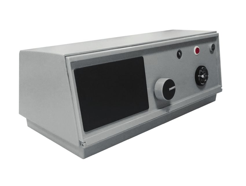
(“fig. 1”), girare il pannello frontale (A). Per accedere ai terminali di collegamento e per estendere i tubi capillari dei termostati e del termometro,
rimuovere prima il pannello superiore (B), quindi rimuovere le 2 viti laterali (C). Il termostato di regolazione (TRC) può essere regolato dall’utente
tramite la manopola anteriore. Il termostato di sicurezza è a regolazione fissa ed è dotato della funzione di ripristino manuale.
È obbligatorio:
• l’uso di un interruttore magnetotermico bipolare, disgiuntore di linea, in conformità alle norme CEI-EN (apertura dei contatti di minimo 3 mm)
• rispettare il collegamento L1 (fase) - N (neutro)
• utilizzare cavi con sezione maggiore o uguale a 1,5 mm2 che includono i terminali
• consultare gli schemi elettrici del presente manuale d’istruzioni per qualsiasi intervento di tipo elettrico
• realizzare un collegamento a terra idoneo
• è proibito l’uso dei tubi dell'acqua per la messa a terra dell’apparecchio.
Il costruttore non è responsabile per eventuali danni causati dalla mancata messa a terra dell’apparecchio e dall’inadempimento rispetto a
quanto riportato negli schemi elettrici.
TS SB IG
TRC 6
fig. 1
IG Interruttore generale TS Riarmo / Termostato sicurezza
SB Spia blocco bruciatore 6 Termometro
TRC Termostato di regolazione
cod. 3541R600 - Rev. 00 - 01/2019
2 ITPannello di controllo
Schema della morsettiera dei collegamenti elettrici (“fig. 2”)
Legenda:
IG Interruttore generale TRC (TR1 - TR2) Termostato 2 stadi 1° - 2°
TS Termostato sicurezza 100°C fiamma (40°-85°C Δt 1°-2° fiamma = 7°C)
TA Termostato ambiente CA Contatto ausiliario
SB Spia blocco bruciatore CB Connettore bruciatore
TC Termostato circolatore CB2 Connettore bruciatore 2° stadio
fig. 2
Legenda morsetti:
3 Linea bruciatore 12 - 13 Consenso ausiliario
4 Neutro bruciatore 14 - 15 Circolatore
5 Massa bruciatore 16 Massa Circolatore
6 - 7 Consenso bruciatore 17 - 18 - 19 Consenso 2° stadio
8 Blocco bruciatore
10 - 11 Termostato ambiente Le connessioni tratteggiate sono a cura dell’installatore
cod. 3541R600 - Rev. 00 - 01/2019
IT 3Control panel
CONTROL PANEL
0Q2K10XA – Thermostatic control panel, 2 stages
Thermostatic control panel, 2 burner stage
It’s made of plastic with protection index IP40, and houses adjustment and safety instruments. The panels include a thermostat signal to control
the anti-condensation pump.
The electrical system for the boiler must be:
• designed and installed by qualified personnel and connected to a grounding system in accordance with current legal standards.
• suitable for the maximum power absorbed by the boiler, using electrical cables with the appropriate cross-section.
The ground wire in the power cables and cables connecting to the boiler must be several mm longer than the other wires in the same cable.
For connections between the burner, electrical panel and electrical power supply, the use of H07 RN-F cables is recommended for visible con-
nections. For other types of systems, or for special environmental situations, consult current standards. The composition and diameter of the
wires is calculated based on the power absorbed by the burner. To access the instruments , rotate the front panel (A). To access the connection
terminals (“fig. 1”) and unwind the capillary tubes from the thermostats and thermometer, remove the top panel (B) after first removing the 2
side screws (C). The control thermostats (TRC) can be set by the user, using the knob at the front. The safety thermostat has a fixed setting
and manual reset.
The following are compulsory:
• use a two-pole, thermal-magnetic overload switch, mains disconnecting switch, in accordance with CEI-EN standards (minimum contact
opening of 3 mm)
• respect the connection L1 (Phase) - N (Neutral)
• use cables with a cross-section greater than or equal to 1.5 mm2, including terminals
• refer to the wiring diagrams in this instructions manual for any operations on the electrical system
• effectively ground the appliance
• it is forbidden to use water hoses to ground the appliance.
The manufacturer is not liable for any damage caused by the failure to ground the appliance, or for non-compliance with the wiring diagrams.
TS SB IG
TRC 6
fig. 1
IG Main switch TS Reset / Safety thermostat
SB Burner shutdown signal 6 Thermometer
TRC Regulation thermostat
cod. 3541R600 - Rev. 00 - 01/2019
4 ENControl panel
Diagram of the terminal board and of the electrical connections (“fig. 2”)
Key:
IG Main switch TRC (TR1 - TR2) 2 stage thermostat 1° - 2°
TS Safety thermostat flame (40°-85°C Δt 1°-2° flame = 7°C)
TA Room thermostat CA Auxiliary contact
SB Burner shutdown signal CB Burner connection
TC Pump thermostat CB2 Burner connection 2 stage
fig. 2
Key:
3 Burner line 12 - 13 Auxiliary contact
4 Burner phase 14 - 15 Pump
5 Burner ground 16 Burner ground
6-7 Burner consent 17 - 18 - 19 2nd stage consent
8 Burner shutdown
10 - 11 Room thermostat The dotted connections are the installer’s responsibility.
cod. 3541R600 - Rev. 00 - 01/2019
EN 5Puoi anche leggere