MANUAL MANUALE TECNICO PER L'INSTALLATORE TECHNICAL INSTALLATION - FOR PELLET STOVE - Sercatec
←
→
Trascrizione del contenuto della pagina
Se il tuo browser non visualizza correttamente la pagina, ti preghiamo di leggere il contenuto della pagina quaggiù
Lo23 IDRO_controllore per
       stufa a pellet
L023 HYDRO_ContrOL BOARD
      FOR PELLET STOVE

   MANUALE TECNICO
  PER L’INSTALLATORE
TECHNICAL INSTALLATION
        MANUAL
ITA
Micronova Controllore L023
data 11/06/2016
INDICE pag. 2 di 83
INDICE
1. PREFAZIONE 6
2. REVISIONI 6
3. INTRODUZIONE 6
3.1 Abbreviazioni 6
3.2 Ambito di applicazione 6
3.3 Descrizione generale 6
3.4 Accessori 8
3.5 Normative 8
4. SPECIFICHE TECNICHE 8
4.1 Specifiche elettriche 8
4.2 Specifiche ambientali 10
4.3 Specifiche meccaniche 10
4.4 Connessioni 10
5. INSTALLAZIONE 14
5.1 Test automatico del sistema 14
5.2 Prima accensione dell’apparato 14
6. INTERFACCIA UTENTE 14
6.1 Descrizione della console 16
6.2 A che cosa servono i pulsanti 18
7. IL MENU 20
7.1 Menu utente 20
7.2 Menu 01 - regola ventole 24
7.3 Menu 02 - set orologio 24
7.4 Menu 03 - set crono 26
7.5 Menu 04 - scegli lingua 32
7.6 Menu 05 - modo stand-by 32
7.7 Menu 06 - modo cicalino 32
7.8 Menu 07 - carico iniziale 34
7.9 Menu 08 - stato stufa 34
8. MODALITÀ OPERATIVA (UTENTE) 36
8.1 Accensione della stufa 36
8.2 Fase di avvio 36
8.3 Passaggio da spento a lavoro 38
8.4 Mancata accensione 40
8.5 Stufa in lavoro 40
8.6 Modifica dell’impostazione della temperatura ambiente 40
8.7 Impiego del termostato/cronotermostato esterno 40
8.8 La temperatura ambiente raggiunge il SET impostato 42
8.9 Pulizia del braciere 42
8.10 Spegnimento della stufa 44
8.11 Stufa spenta 44
8.12 Riaccensione della stufa 44
9. CHE COSA SUCCEDE SE 46
9.1 Il pellet non si accende 46
9.2 Manca l’energia elettrica 46
Micronova S.r.l. - Via A. Niedda, 3 - 35010 Vigonza (PD) - +39 049 8931563 - +39 049 8931346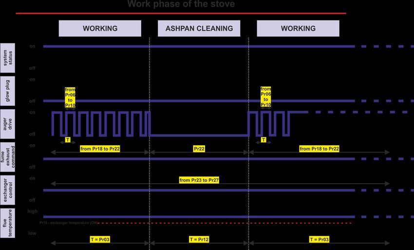
ENG
Micronova Control board L023
date 11/06/2016
page 3 of 83
INDEX
INDEX
1. PREFACE 7
2. REVISIONS 7
3. INTRODUCTION 7
3.1 Abbreviations 7
3.2 Scope 7
3.3 General description 7
3.4 Accessories 9
3.5 Regulations 9
4. TECHNICAL SPECIFICATION 9
4.1 Electrical specifications 9
4.2 Environmental specifications 11
4.3 Mechanical specifications 11
4.4 Connections 11
5. INSTALLATION 15
5.1 Automated system test 15
5.2 Starting your pellet stove 15
6. USER INTERFACE 15
6.1 Description of the console 17
6.2 What are the buttons for 19
7. MENU 21
7.1 User menu 21
7.2 Menu 01 - fan regulation 25
7.3 Menu 02 - set clock 25
7.4 Menu 03 - set timer program 27
7.5 Menu 04 - language selection 33
7.6 Menu 05 - standby mode 33
7.7 Menu 06 - alarm mode 33
7.8 Menu 07 - initial charging 35
7.9 Menu 08 - stove status 35
8. OPERATING MODE (USER) 37
8.1 Lighting the stove 37
8.2 Lighting phase 37
8.3 Transition from off to working 39
8.4 Lighting failure 41
8.5 Working mode 41
8.6 Adjusting the room temperature setting 41
8.7 How to use the external thermostat/programmable thermostat 41
8.8 Room temperature reaches the set temperature 43
8.9 Cleaing the ashpan 43
8.10 Switching off the stove 45
8.11 Stove in off mode 45
8.12 Reigniting the stove 45
9. WHAT HAPPENS IF 47
9.1 The pellet does not turn on 47
9.2 There is a power outage (black out) 47
Micronova S.r.l. - Via A. Niedda, 3 - 35010 Vigonza (PD) - +39 049 8931563 - +39 049 8931346
ITA
Micronova Controllore L023
data 11/06/2016
INDICE pag. 4 di 83
segue INDICE
10.ALLARMI 48
10.1 Allarme sonda temperatura fumi 48
10.2 Allarme sovra temperatura fumi 48
10.3 Allarme per mancata accensione 50
10.4 Allarme spegnimento durante la fase di lavoro 50
10.5 Allarme termostato sicurezza coclea 50
10.6 Allarme termostato generale 52
10.7 Allarme ventilatore aspirazione guasto 52
11.MODALITÀ OPERATIVA (MENU TECNICO) 54
11.1 Sottomenu 09 - 01 - 01 carica pellet 58
11.2 Sottomenu 09 - 02 - 01 tipo camino 58
11.3 Sottomenu 09 - 03 banche dati 58
11.4 Sottomenu 09 - 04 dati canalizzata 58
11.5 Sottomenu 09 - 05 tarature varie 58
11.6 Sottomenu 09 - 06 test uscite 60
11.7 Sottomenu 09 - 07 tarature fabbrica 60
11.8 Sottomenu 09 - 08 azzera ore parziali 60
11.9 Sottomenu 09 - 09 azzera allarmi 60
11.10 Sottomenu 09 - 10 memorie contatori 60
11.11 Taratura della sonda fumi 62
11.12 Struttura della memoria del controllore 64
11.13 Creazione di banche dati personalizzate 66
12.AGGIORNAMENTO DEL FIRMWARE DELLA SCHEDA 68
APPENDICE A (Tabella parametri) 70
APPENDICE B (Sequenza di avvio e condizione di lavoro) 76
APPENDICE C (Parametri di utilizzo) 80
Micronova S.r.l. - Via A. Niedda, 3 - 35010 Vigonza (PD) - +39 049 8931563 - +39 049 8931346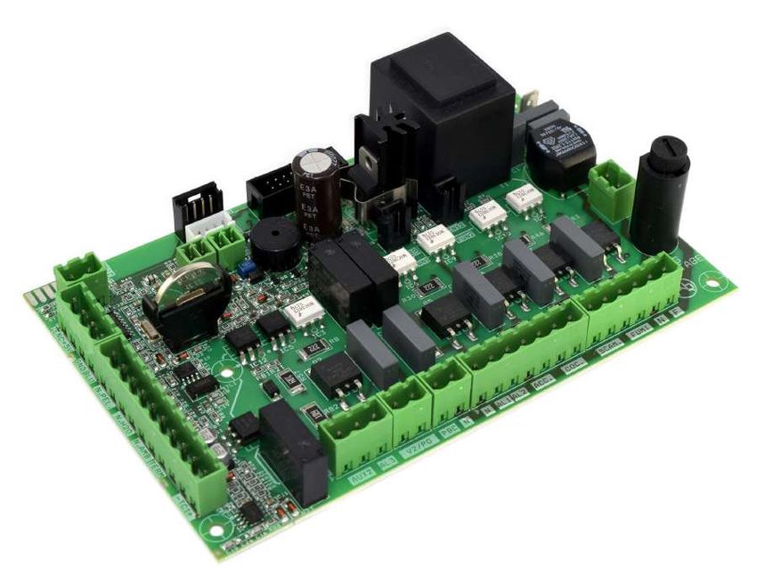
ENG
Micronova Control board L023
date 11/06/2016
page 5 of 83
INDEX
INDEX continued
10.ALARMS 49
10.1 Flue gas temperature probe alarm 49
10.2 Flue gas over-temperature alarm 49
10.3 Ignition failure alarm 51
10.4 Shut down during working mode alarm 51
10.5 Pressure switch for auger safety alarm 51
10.6 General thermostat alarm 53
10.7 Exhaust malfunction alarm 53
11.OPERATING MODE (TECHNICAL MENU) 55
11.1 Submenu 09 - 01 - 01 load pellet 59
11.2 Submenu 09 - 02 - 01 chimney type 59
11.3 Submenu 09 - 03 databases 59
11.4 Submenu 09 - 04 channel data 59
11.5 Submenu 09 - 05 various adjustments 59
11.6 Submenu 09 - 06 output test 61
11.7 Submenu 09 - 07 factory settings 61
11.8 Submenu 09 - 08 reset partial hours 61
11.9 Submenu 09 - 09 reset alarms 61
11.10 Submenu 09 - 10 meter memory 61
11.11 Flue probe reset 63
11.12 Control board memory structure 65
11.13 Creating personalized databases 67
12.CONTROL BOARD FIRMWARE UPDATE 69
APPENDIX A (Parameter table) 71
APPENDIX B (Start up sequence and working conditions) 77
APPENDIX C (Usage parameters) 81
Micronova S.r.l. - Via A. Niedda, 3 - 35010 Vigonza (PD) - +39 049 8931563 - +39 049 8931346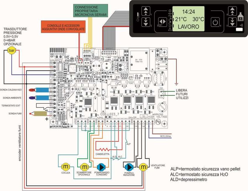
ITA
Micronova Controllore L023
data 11/06/2016
INTRODUZIONE pag. 6 di 83
1. PREFAZIONE
versione data codice progetto redatto da
1.0 16.03.2011 L023 Michele Rossetti
2. REVISIONI
revisione
versione data descrizione modifiche redatto da
precedente
1_Aggiornate tutte le immagini
2_Aggiunta la traduzione in inglese
del manuale
1.1 11.06.2016 1.0 Nicola Cabbia
3_Aggiornate le specifiche in seguito
all’aggiunta della pompa basso
consumo
3. INTRODUZIONE
3.1 Abbreviazioni
Sono utilizzate le seguenti abbreviazioni:
BI .PEL Taglia fuoco
Accend. Candeletta
C. Risc. Pompa riscaldamento
C. San. Pompa sanitari
ALF Termostato di sicurezza generale
ALF Termostato di sicurezza coclea
EEPROM Memoria non volatile riscrivibile (Electrically Eraseble Programmable
Read Only Memory)
3.2 Ambito di applicazione
Il presente documento descrive il controllore L023. Tale dispositivo è stato realizzato
per lo specifico impiego nelle stufe a pellet idro di cui gestisce tutte le funzionalità
attraverso un adeguato numero di ingressi e uscite.
3.3 Descrizione generale
Il controllore è costituito da una scheda elettronica provvista di una serie di connettori
che permettono il collegamento della scheda ai vari dispositivi principalmente costituiti
da:
• console di comando realizzata in varie versioni e con elevato grado di per-
sonalizzazione.
• Sensori (temperatura, ecc.).
• Ventilatori.
• Coclea.
• Candeletta.
• Allarmi.
• Interfacce di comunicazione (RS232, Bluetooth, ecc.).
• Pompa (circolatore).
Micronova S.r.l. - Via A. Niedda, 3 - 35010 Vigonza (PD) - +39 049 8931563 - +39 049 8931346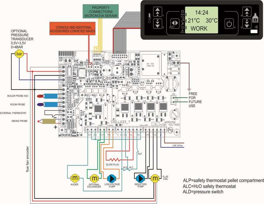
ENG
Micronova Control board L023
date 11/06/2016
page 7 of 83
INTRODUCTION
1. PREFACE
version date project code written by
1.0 16.03.2011 L023 Michele Rossetti
2. REVISIONS
previous
version date description of the changes written by
revision
1_All images have been updtated
2_English translation of the manual
1.1 11.06.2016 1.0 has been added Nicola Cabbia
3_Specifications have been added for
the addition of a low-voltage pump
3. INTRODUCTION
3.1 Abbreviations
The following abbreviations are used:
BI .PEL Fire door
Accend. Glow plug
C. Risc. Heating pump
C. San. Sanitary pump
ALF General safety thermostat
ALF Auger safety thermostat
EEPROM Electrically Eraseble Programmable Read Only Memory
3.2 Scope
The present document describes the L023 control board. This device was specifically
made for usage in hydro pellet stoves. It manages all of the stove’s functions through
an adequate number of inputs and outputs.
3.3 General description
The control board is made up of a circuit board equipped with a series of connectors
that allow the circuit board to connect to the various devices, which include the
following:
• the console (or control panel) of which several versions have been produced
and which is highly personalizable.
• Sensors (temperature, etc.).
• Fans.
• Auger.
• Glow plug.
• Alarms.
• ICommunication interfaces (RS232, Bluetooth, ecc.).
• Pump (circulator).
Micronova S.r.l. - Via A. Niedda, 3 - 35010 Vigonza (PD) - +39 049 8931563 - +39 049 8931346
ITA
Micronova Controllore L023
data 11/06/2016
SPECIFICHE TECNICHE pag. 8 di 83
3.4 Accessori
Il dispositivo può essere dotato di:
• Cronotermostato settimanale
• Telecomando IR (attraverso la console)
• Sensore debimetro
• Sensore livello pellet
• Contenitore in ABS in versione standard e autoestinguente UL 94 V0
• Console LCD
3.5 Normative
Il dispositivo è realizzato in conformità alle seguenti normative:
• EN 55011
• EN 61000-3-2
• IEC/EN 61000-4-2, -4, -5, -6, -8, -9, -11, -29
4. SPECIFICHE TECNICHE
Sono qui di seguito elencate le specifiche del dispositivo. Fare anche riferimento alla figura 1
che illustra le connessioni elettriche alla scheda.
4.1 Specifiche elettriche
Alimentazione
Tensione di alimentazione 230Vca ± 15%, 50/60 Hz
Consumo max (esclusa console e utilizzatori) 50 mA
Consumo max (console collegata esclusi utilizzatori) 55 mA
Ingressi
Termocoppia temperatura fumi Termocoppia tipo J
Termostato esterno Contatto n.a.
Sonda NTC temperatura ambiente NTC 10 kΩ
Sonda NTC temperatura acqua NTC 10 kΩ
Sonda NTC temperatura pellet NTC 10 kΩ
Console -
Encoder velocità rotazione estrattore fumi -
Scheda opzionale cronotermostato -
Termostato di sicurezza generale 230Vca
Pressostato di sicurezza 230Vca
Connessione seriale (da utilizzare con adattatore) -
Uscite
Aspiratore fumi (con reg. a controllo di fase) 230 Vca (TRIAC)
Scambiatore aria n°1 (con reg. a controllo di fase) 230 Vca (TRIAC)
Scambiatore aria n°2 (con reg. a controllo di fase) 230 Vca (TRIAC)
Scambiatore aria n°3 (con reg. a controllo di fase) 230 Vca (TRIAC)
Motore coclea 230 Vca (TRIAC)
Candeletta 230 Vca (Contatto)
Micronova S.r.l. - Via A. Niedda, 3 - 35010 Vigonza (PD) - +39 049 8931563 - +39 049 8931346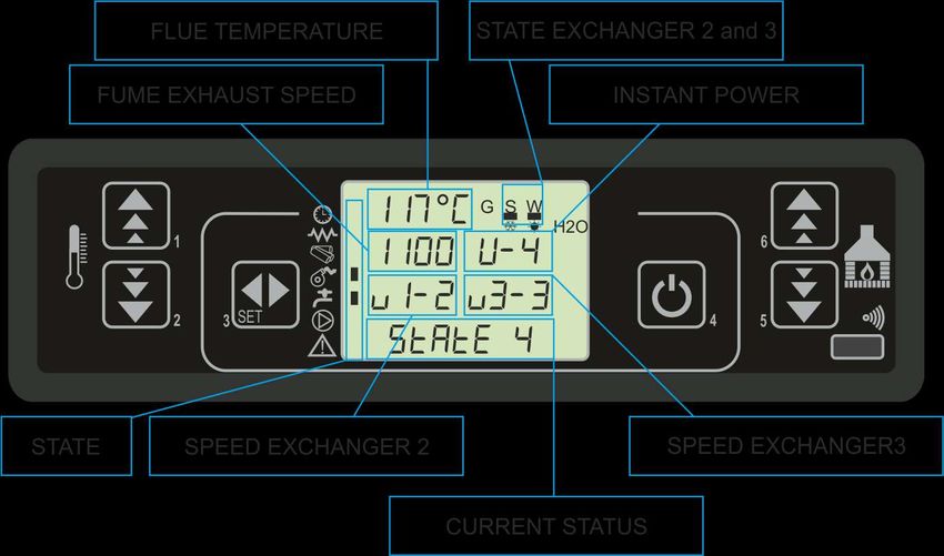
ENG
Micronova Control board L023
date 11/06/2016
page 9 of 83
TECHNICAL SPECIFICATIONS
3.4 Accessories
The device can include:
• Weekly programmable thermostat
• IR remote (through the console)
• Air flow meter
• Pellet level sensor
• Standard self-extinguishing ABS container UL 94 V0
• LCD Console
3.5 Regulations
The device is manufactured according to the following standards:
• EN 55011
• EN 61000-3-2
• IEC/EN 61000-4-2, -4, -5, -6, -8, -9, -11, -29
4. TECHNICAL SPECIFICATIONS
Here, as follows, is a list of the device specifications. Please refer to figure 1 for an
illustartion of the circuit’s electrical connections.
4.1 Electrical specifications
Power source
Supply voltage 230Vac ± 15%, 50/60 Hz
Max consumption (excluding console and users) 50 mA
Max consumption (console connected excl. users) 55 mA
Inputs
Flue temperature thermocouple Thermocouple type J
External thermostat Contact n.o.
Room temperature NTC probe NTC 10 kΩ
Water temperature NTC probe NTC 10 kΩ
Pellet temperature NTC probe NTC 10 kΩ
Console -
Fume extractor rotation speed encoder -
Optional programmable thermostat control board -
General safety thermostat 230Vac
Safety pressure switch 230Vac
Serial connection (to be used with an adaptor) -
Outputs
Fume exhaust (with phase control regulation) 230 Vac (TRIAC)
Exchanger fan no.1 (with phase control regulation) 230 Vac (TRIAC)
Exchanger fan no.2 (with phase control regulation) 230 Vac (TRIAC)
Exchanger fan no.3 (with phase control regulation) 230 Vac (TRIAC)
Auger motor 230 Vac (TRIAC)
Glow plug 230 Vac (Contact)
Micronova S.r.l. - Via A. Niedda, 3 - 35010 Vigonza (PD) - +39 049 8931563 - +39 049 8931346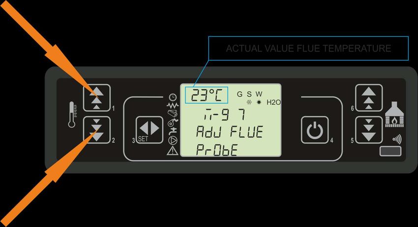
ITA
Micronova Controllore L023
data 11/06/2016
CONNESSIONI pag. 10 di 83
4.2 Specifiche ambientali
Temperatura ambiente operativa da 0°C a +60°C
Temperatura di immagazzinamento da -10°C a +60°C
Umidità relativa massima (senza condensa) 95%
4.3 Specifiche meccaniche
Dimensioni scheda (LxPxH) (*) (125 x 101 x 35) mm
Peso 250 g circa
Dimensioni contenitore ABS (189 x 110 x 70) mm
Posizione di montaggio qualsiasi
Grado di protezione in versione con contenitore ABS IP 21
(*) con opzione cronotermostato altezza H = 40 mm
4.4 Connessioni
Qui di seguito è riportato lo schema tipico di connessione del controllore.
fig.1
Micronova S.r.l. - Via A. Niedda, 3 - 35010 Vigonza (PD) - +39 049 8931563 - +39 049 8931346ENG
Micronova Control board L023
date 11/06/2016
page 11 of 83
CONNECTIONS
4.2 Environmental specifications
Operational room temperature da 0°C a +60°C
Storage temperature da -10°C a +60°C
Maximum relative humidity (without condensation) 95%
4.3 Mechanical specifications
Control board dimensions (LxWxH) (*) (125 x 101 x 35) mm
Weight 250 g approximately
ABS container dimensions (189 x 110 x 70) mm
Assembly position Any
Degree of protection in version with ABS container IP 21
(*) with programm. thermostat option H = 40 mm
4.4 Connections
Here, as follows, is a typical circuit board wiring diagram.
fig. 1
Micronova S.r.l. - Via A. Niedda, 3 - 35010 Vigonza (PD) - +39 049 8931563 - +39 049 8931346ITA
Micronova Controllore L023
data 11/06/2016
INSTALLAZIONE pag. 12 di 83
La tabella seguente riporta nel dettaglio i connettori disponibili con relativa piedinatura e
descrizione funzionale.
connettore pin etichetta descrizione
CN1 - - Terminale a innesto rapido di terra
CN2 1-2 AUX Uscita ventilatore aria n°2
CN4 1 N Neutro
2 AL1 Ingresso allarme termometro di sicurezza (230Vca)
3 AL2 Ingresso allarme pressostato di sicurezza (230Vca)
4-5 ACC Uscita candeletta (230Vca)
6-7 COC Uscita motore coclea (230Vca)
CN5 - DISPLAY Connettore per la console
CN6 1-2 V2/PO Uscita ventilatore aria n°3 (circolatore)
CN7 1-2 N. PEL Ingresso sonda temperatura aria/pellet (non utilizzato)
3-4 N. H20 Ingresso sonda temperatura acqua (non utilizzato)
5-6 N. AMB Ingresso sonda temperatura ambiente
7-8 TERM Ingresso termostato esterno
9 - 10 -TC+ Ingresso termocoppia fumi
CN8 1-2 SCAM Uscita ventilatore scambiatore n° 1
3-4 FUMI Uscita rete
5-6 N-F Alimentazione scheda (230Vca)
CN9 1 ENC Ingresso encoder ventilatore fumi
3 +5V Alimentazione encoder a + 5V
4 GND Comune ingresso encoder
5 BLUE Non utilizzato
CN11 - JTAG Connettore programmazione di fabbrica
CN13 - SERIALE Connessione seriale da usare con adattatore
CN15 1-2 AUX IN Ingresso ausiliario
CN18 - DEBIME- Connessione sonda debimetro
TRO
CN19 1-2 AUX2/ Sicurezza coclea
AL3
CN17 CN21 1-2 / 3-4 - Onde convogliate
CN22 1 PBC Pompa basso consumo
2 N Neutro
Micronova S.r.l. - Via A. Niedda, 3 - 35010 Vigonza (PD) - +39 049 8931563 - +39 049 8931346ENG
Micronova Control board L023
date 11/06/2016
page 13 of 83
INSTALLATION
The following table demonstrates in detail the available connectors and the relative pinout
and functional descriptions.
connector pin label description
CN1 - - Quick connect ground terminal
CN2 1-2 AUX Air fan output no.2
CN4 1 N Neutral
2 AL1 Security temperature sensor alarm input (230 Vac)
3 AL2 Security pressure switch alarm input (230Vac)
4-5 ACC Glow plug output (230Vac)
6-7 COC Auger motor output (230Vac)
CN5 - DISPLAY Console connector
CN6 1-2 V2/PO Air fan output no.3 (circulator)
CN7 1-2 N. PEL Air/pellet temperature probe input (not used)
3-4 N. H20 Water temperature probe input (not used)
5-6 N. AMB Room temperature probe input
7-8 TERM External thermostat input
9 - 10 -TC+ Flue thermocouple input
CN8 1-2 SCAM Exchanger fan output no.1
3-4 FUMI Flue fan output
5-6 N-F Control board power (230Vac)
CN9 1 ENC Flue fan encoder input
3 +5V Encoder power (+ 5Vdc)
4 GND Encoder common input
5 BLUE Not used
CN11 - JTAG Factory programming conenctor
CN13 - SERIALE Serial connection to be used with adaptor
CN15 1-2 AUX IN Auxiliary input
CN18 - DEBIME- Connection to air flow meter probe
TRO
CN19 1-2 AUX2/ Auger safety
AL3
CN17 CN21 1-2 / 3-4 - Conveyed waves
CN22 1 PBC Pompa basso consumo
2 N Neutro
Micronova S.r.l. - Via A. Niedda, 3 - 35010 Vigonza (PD) - +39 049 8931563 - +39 049 8931346ITA
Micronova Controllore L023
data 11/06/2016
INSTALLAZIONE pag. 14 di 83
5. INSTALLAZIONE
Installare la scheda all’interno della stufa in posizione tale da non dover superare i limiti
della temperatura operativa riportata in specifica. I cavi e i morsetti in dotazione sono
sufficienti a garantire il corretto cablaggio delle connessioni a tutti gli elementi del circuito
elettrico. Fare riferimento alla figura 1 per i dettagli.
5.1 Test automatico del sistema
Micronova mette a disposizione un sistema automatico di test di fine linea produzione
che permette di effettuare tutte le verifiche necessarie ad assicurare la corretta
realizzazione del montaggio della scheda e delle varie parti esterne (sonde, motori,
ecc.).
5.2 Prima accensione dell’apparato
Dopo essersi assicurati di aver eseguito l’installazione a regola d’arte, è possibile
passare alla prima accensione che prevede anche tutte le operazioni di settaggio dei
parametri, settaggio che può indifferentemente avvenire attraverso i tasti della console
oppure, in maniera più veloce e sicura, utilizzando un personal computer e il software
di interfaccia, oppure utilizzando il sistema di programmazione fornibile da
Micronova. Disponendo del sistema automatico di test, tale operazione risulta
completamente automatizzata e inclusa nelle varie fasi del test finale dell’apparato.
6. INTERFACCIA UTENTE
L’unità console permette di colloquiare con il controllore con la semplice pressione di
alcuni tasti. Un display informa l’operatore sullo stato operativo della stufa. In modalità
programmazione sono visualizzati i vari parametri che possono essere modificati
agendo sui tasti.
Sia la configurazione del pannello display che la serigrafia sono personalizzabili su
disegno del cliente.
Le informazioni fornite nel presente manuale fanno riferimento alla scheda munita di
opzione cronotermostato.
Micronova S.r.l. - Via A. Niedda, 3 - 35010 Vigonza (PD) - +39 049 8931563 - +39 049 8931346ENG
Micronova Control board L023
date 11/06/2016
page 15 of 83
INSTALLATION
5. INSTALLATION
Install the circuit board inside the stove in such a position that will prohibit it from
exceeding the operational temperature specifically indicated. The cables and clips provided
are sufficient enough to guarantee the correct wiring of the connections to all the various
elements of the electrical circuit. Please refer to figure 1 for more details.
5.1 Automated system test
Micronova provides an automated end-of-production-line testing system that allows
for the necessary verifications to assure the correct assembly of the circuit board and
the various external parts (probes, motors, etc.).
5.2 Starting your pellet stove
Once you are certain to have correctly followed the installation instructions, you can
start your pellet stove for the first time. This includes all of the parameter setting steps.
These can be set through the use of the buttons on the console or, more quickly and
more safely, through the use of a personal computer and the interface software, as well
as through the use of the programming system that can be provided by Micronova. By
using the automated testing system, this operation is completely automatic and included
in the various phases of the final test of the device.
6. USER INTERFACE
Through the console you can have a dialogue with the control board simply by pressing
a few buttons. The display informs the operator on the working status of the stove. In
programming mode the various settings can be visualized and modified through the use
of the buttons.
Both the appearance of the display panel and the silk screen print are customizable by
the client.
The information available in the present manual refers to the control board equipped
with the programmable thermostat option.
Micronova S.r.l. - Via A. Niedda, 3 - 35010 Vigonza (PD) - +39 049 8931563 - +39 049 8931346ITA
Micronova Controllore L023
data 11/06/2016
CONSOLE pag. 16 di 83
6.1 Console
La console visualizza le informazioni sullo stato di funzionamento della stufa.
Accedendo al menu è possibile ottenere vari tipi di visualizzazione ed effettuare le
impostazioni disponibili a seconda del livello di accesso.
Dipendendo dalla modalità operativa, le visualizzazioni possono assumere differenti
significati a seconda della posizione sul display.
In figura 2 esempio in condizioni di stufa spenta o accesa.
fig.2
La figura 3 descrive il significato dei segnalatori di stato sulla
parte sinistra del display.
L’attivazione nel display di uno dei segmenti nell’area “stato”
segnala l’attivazione del dispositivo corrispondente secondo
l’elenco a fianco.
fig.3
fig.4
In figura 4 è descritta la disposizione dei messaggi in fase di programmazione o
impostazione dei parametri operativi. In particolare:
1. L’area input visualizza i valori di programmazione immessi
2. L’area livello di menu visualizza il livello di menu corrente. Confronta il
capitolo menu.
Micronova S.r.l. - Via A. Niedda, 3 - 35010 Vigonza (PD) - +39 049 8931563 - +39 049 8931346ENG
Micronova Control board L023
date 11/06/2016
page 17 of 83
CONSOLE
6.1 Console
The console displays information on the working status of the stove. By accessing the
menu you can gain access to different views and change the various available settings
based on the access level.
Depending on the operating mode, the various positions on the display can gain
different meanings.
Figure 2 is an example of the display when the stove is either on or off.
fig.2
Figure 3 demonstrates the meanings of the status
symbols on the left of the display.
The activation of one of the symbols in the “status”
area on the display indicates the activation of the
corresponding device according to the list.
fig.3
fig.4
Figure 4 depicts the layout of the messages in the programming or setting phase.
Particularly:
1. The input section displays the chosen settings.
2. The menu level section displays the current menu level. See the chapter about
the menu.
Micronova S.r.l. - Via A. Niedda, 3 - 35010 Vigonza (PD) - +39 049 8931563 - +39 049 8931346ITA
Micronova Controllore L023
data 11/06/2016
CONSOLE pag. 18 di 83
6.2 A che cosa servono i pulsanti
pulsante descrizione modalità azione
PROGRAMMAZIONE Modifica/incrementa il valore di menu selezionato
Incrementa
1 temperatura Incrementa il valore della temperatura del termostato
LAVORO/SPENTO
acqua/ambiente
PROGRAMMAZIONE Modifica/decrementa il valore di menu selezionato
Decrementa
2 temperatura Decrementa il valore della temperatura del termostato
LAVORO/SPENTO
acqua/ambiente
- Accede al MENU
3 Menu MENU Accede al successivo livello di sottomenu
PROGRAMMAZIONE Imposta valore e passa alla voce di menu successiva
Premuto per 2 secondi accende o spegne la stufa se è
LAVORO
spenta o accesa rispettivamente
ON/OFF
4 sblocco
BLOCCO Sblocca la stufa e la riporta nello stato spento
MENU/ Si porta al livello di menu superiore, le modifiche
PROGRAMMAZIONE effettuate sono memorizzate
LAVORO/SPENTO Modifica la potenza resa dalla stufa
Decrementa
5 potenza
MENU Passa alla voce di menu successiva
Torna alla voce di sottomenu successivo, le modifiche
PROGRAMMAZIONE
effettuate sono memorizzate
LAVORO/SPENTO Modifica la velocità dello scambiatore
Incrementa
6 potenza
MENU Passa alla voce di menu precedente
Passa alla voce di sottomenu precedente, le modifiche
PROGRAMMAZIONE
effettuate sono memorizzate
Micronova S.r.l. - Via A. Niedda, 3 - 35010 Vigonza (PD) - +39 049 8931563 - +39 049 8931346ENG
Micronova Control board L023
date 11/06/2016
page 19 of 83
CONSOLE
6.2 What are the buttons for?
button description mode action
PROGRAMMING Adjust/increase the value in the selected menu
Increase
1 temperature Increase the temperature value of the water/room
ON/OFF
thermostat
PROGRAMMING Adjust/decrease the value in the selected menu
Decrease
2 temperature Decrease the temperature value of the water/room
ON/OFF
thermostat
- Accesses the menu
3 Menu MENU Accesses the submenu level
PROGRAMMING Sets the value and moves to the next menu
Hold for 2 seconds to switch the stove on when in off
ON
mode, or off when in on mode
ON/OFF
4 unlock
LOCK Unlocks the stove and puts it into off mode
MENU/ Brings you to the next menu level, any adjustments made
PROGRAMMING will be saved
ON/OFF Adjust the power produced by the stove
Decrease
5 power
MENU Takes you to the next menu level
Takes you to the next submenu, any adjustments made
PROGRAMMING
will be saved
ON/OFF Adjust the speed of the exchanger
Increase
6 power
MENU Takes you back to the previous menu level
Takes you to the previous submenu, any adjustments made
PROGRAMMING
will be saved
Micronova S.r.l. - Via A. Niedda, 3 - 35010 Vigonza (PD) - +39 049 8931563 - +39 049 8931346ITA
Micronova Controllore L023
data 11/06/2016
MENU UTENTE pag. 20 di 83
7. IL MENU
Con pressione sul tasto P3 (MENU) si accede al menu.
Questo è suddiviso in varie voci e livelli che permettono di accedere alle impostazioni e
alla programmazione della scheda.
Le voci di menu che consentono di accedere alla programmazione tecnica sono protette da
chiave.
7.1 Menu utente
Il prospetto seguente descrive sinteticamente la struttura del menu soffermandosi in
questo paragrafo alle sole selezioni disponibili per l’utente.
La voce di menu 01-regola ventole è presente solamente se la funzione
corrispondente è stata abilitata (vedi parametri tecnici).
livello 1 livello 2 livello 3 livello 4 valore
01 - regola ventole *rif. pag. 13 cap. 7.2
02 - set orologio
01 - giorno giorno settimana
02 - ore ora
03 - minuti minuto
04 - giorno giorno mese
05 - mese mese
06 - anno anno
03 - set crono
01 - abilita crono
01 - abilita crono on/off
02 - program giorno
01 - crono giorno on/off
02 - start 1 giorno ora
03 - stop 1 giorno ora
04 - start 2 giorno ora
05 - stop 2 giorno ora
03 - program settim
01 - crono settim on/off
02 - start prog 1 ora
03 - stop prog 1 ora
04 - lunedì prog 1 on/off
05 - martedì prog 1 on/off
06 - mercoledì prog 1 on/off
07 - giovedì pog 1 on/off
08 - venerdì prog 1 on/off
09 - sabato prog 1 on/off
Micronova S.r.l. - Via A. Niedda, 3 - 35010 Vigonza (PD) - +39 049 8931563 - +39 049 8931346ENG
Micronova Control board L023
date 11/06/2016
page 21 of 83
USER MENU
7. MENU
You can gain access to the menu by pressing the P3 (MENU) button.
It is divided into various items and levels that allow you to access the settings and circuit
board programming.
The items on the menu that allow you to access the technical programming are passcode
protected.
7.1 User menu
The following table briefly describes the menu structure. This paragraph focuses
specifically on the settings available to the user.
Menu item 01-regulate fans is available only if the corresponding function has been
activated (see technical settings).
level 1 level 2 level 3 level 4 value
01 - regulate fans *ref. page 13 cha. 7.2
02 - set clock
01 - day day of week
02 - hours hour
03 - minutes minute
04 - day day of month
05 - month month
06 - year year
03 - set timer
01 - enable timer
01 - enable timer on/off
02 - day program
01 - daily timer on/off
02 - start day 1 time
03 - stop day 1 time
04 - start day 2 time
05 - stop day 2 time
03 - week program
01 - weekly time on/off
02 - start prog 1 time
03 - stop prog 1 time
04 - monday prog 1 on/off
05 - tuesday prog 1 on/off
06 - wednesday prog 1 on/off
07 - thursday pog 1 on/off
08 - friday prog 1 on/off
09 - saturday prog 1 on/off
Micronova S.r.l. - Via A. Niedda, 3 - 35010 Vigonza (PD) - +39 049 8931563 - +39 049 8931346ITA
Micronova Controllore L023
data 11/06/2016
MENU UTENTE pag. 22 di 83
livello 1 livello 2 livello 3 livello 4 valore
10 - domenica prog 1 on/off
11 - start prog 2 ora
12 - stop prog 2 ora
13 - lunedì prog 2 on/off
14 - martedì prog 2 on/off
15 - mercoledì prog 2 on/off
16 - giovedì pog 2 on/off
17 - venerdì prog 2 on/off
18 - sabato prog 2 on/off
19 - domenica prog 2 on/off
20 - start prog 3 ora
21 - stop prog 3 ora
22 - lunedì prog 3 on/off
23 - martedì prog 3 on/off
24 - mercoledì prog 3 on/off
25 - giovedì pog 3 on/off
26 - venerdì prog 3 on/off
27 - sabato prog 3 on/off
28 - domenica prog 3 on/off
29 - start prog 2 ora
30 - stop prog 2 ora
31 - lunedì prog 2 on/off
32 - martedì prog 2 on/off
33 - mercoledì prog 2 on/off
34 - giovedì pog 2 on/off
35 - venerdì prog 2 on/off
36 - sabato prog 2 on/off
37 - domenica prog 2 on/off
04 - program week-end
01 - crono week-end
02 - start 1
03 - stop 1
04 - start 2
05 - stop 2
04 - scegli lingua
01 - italiano set
02 - francese set
03 - inglese set
Micronova S.r.l. - Via A. Niedda, 3 - 35010 Vigonza (PD) - +39 049 8931563 - +39 049 8931346ENG
Micronova Control board L023
date 11/06/2016
page 23 of 83
USER MENU
level 1 level 2 level 3 level 4 VALUE
10 - sunday prog 1 on/off
11 - start prog 2 time
12 - stop prog 2 time
13 - monday prog 2 on/off
14 - tuesday prog 2 on/off
15 - wednesday prog 2 on/off
16 - thursday pog 2 on/off
17 - friday prog 2 on/off
18 - saturday prog 2 on/off
19 - sunday prog 2 on/off
20 - start prog 3 time
21 - stop prog 3 time
22 - monday prog 3 on/off
23 - tuesday prog 3 on/off
24 - wednesday prog 3 on/off
25 - thursday pog 3 on/off
26 - friday prog 3 on/off
27 - saturday prog 3 on/off
28 - sunday prog 3 on/off
29 - start prog 2 time
30 - stop prog 2 time
31 - monday prog 2 on/off
32 - tuesday prog 2 on/off
33 - wednesday prog 2 on/off
34 - thursday pog 2 on/off
35 - friday prog 2 on/off
36 - saturday prog 2 on/off
37 - sunday prog 2 on/off
04 - week-end program
01 - week-end timer
02 - start 1
03 - stop 1
04 - start 2
05 - stop 2
04 - language select.
01 - Italian set
02 - French set
03 - English set
Micronova S.r.l. - Via A. Niedda, 3 - 35010 Vigonza (PD) - +39 049 8931563 - +39 049 8931346ITA
Micronova Controllore L023
data 11/06/2016
MENU UTENTE pag. 24 di 83
livello 1 livello 2 livello 3 livello 4 valore
04 - tedesco set
05 - modo stand-by on/off
06 - cicalino on/off
07 - carico iniziale set
08 - stato stufa -
09 - tarature tecniche *rif. pag. 28 cap.11
7.2 Menu 01 - regola ventole
Consente la regolazione indipendente dei due ventilatori supplementari (solo con pr.56
abilitato). Per ciascuno dei due ventilatori sono possibili le scelte da tabella qui sotto.
Agire sui tasti P1 (ventola 2) e P2 (ventola 3) per effettuare le selezioni.
impostazione ventilatore 2 ventilatore 3
A corrispondente alla potenza selezionata corrispondente alla potenza selezionata
0 ventola disattivata ventola disattivata
1 velocità fissa Pr57 velocità fissa Pr62
2 velocità fissa Pr58 velocità fissa Pr63
3 velocità fissa Pr59 velocità fissa Pr64
4 velocità fissa Pr60 velocità fissa Pr65
5 velocità fissa Pr61 velocità fissa Pr66
7.3 Menu 02 - set orologio
Imposta l’ora e la data corrente. La scheda è provvista di batteria al litio che permette
all’orologio interno un’autonomia superiore ai 3/5 anni.
Micronova S.r.l. - Via A. Niedda, 3 - 35010 Vigonza (PD) - +39 049 8931563 - +39 049 8931346ENG
Micronova Control board L023
date 11/06/2016
page 25 of 83
USER MENU
level 1 level 2 level 3 level 4 value
04 - German set
05 - stand-by mode on/off
06 - buzzer on/off
07 - initial charge set
08 - stove status -
09 - technical settings *ref. page 28 cha. 11
7.2 Menu 01 - fan regulation
It allows for the independent regulation of the two supplemental fans (only if pr.56 is
enabled). For each of the two fans the following choices are available (as demonstrated
in the table below). Press the P1 (fan 2) and P2 (fan 3) buttons to select.
settings fan 2 fan 3
A corresponding to the selected power corresponding to the selected power
0 fan off fan off
1 fixed speed Pr57 fixed speed Pr62
2 fixed speed Pr58 fixed speed Pr63
3 fixed speed Pr59 fixed speed Pr64
4 fixed speed Pr60 fixed speed Pr65
5 fixed speed Pr61 fixed speed Pr66
7.3 Menu 02 - set clock
Sets the current time and date. The circuit board comes equipped with a lithium
battery that allows the internal clock to have an autonomy of over 3/5 years.
Micronova S.r.l. - Via A. Niedda, 3 - 35010 Vigonza (PD) - +39 049 8931563 - +39 049 8931346ITA
Micronova Controllore L023
data 11/06/2016
MENU UTENTE pag. 26 di 83
7.4 Menu 03 - set crono
Sottomenu 03 - 01 - abilita crono
Permette di abilitare e disabilitare globalmente tutte le funzioni di
cronotermostato.
Sottomenu 03 - 02 - program giornaliero
Permette di abilitare, disabilitare e impostare le funzioni di cronotermostato
giornaliero.
È possibile impostare due fasce di funzionamento delimitate dagli orari
impostati secondo tabella seguente dove l’impostazione OFF indica all’orologio
di ignorare il comando:
selezione significato valori possibili
START 1 ora di attivazione ora - OFF
STOP 1 ora di disattivazione ora - OFF
START 2 ora di attivazione ora - OFF
STOP 2 ora di disattivazione ora - OFF
Micronova S.r.l. - Via A. Niedda, 3 - 35010 Vigonza (PD) - +39 049 8931563 - +39 049 8931346ENG
Micronova Control board L023
date 11/06/2016
page 27 of 83
USER MENU
7.4 Menu 03 - set timer
Submenu 03 - 01 - enable timer
It allows you to globally enable and disable all of the functions of the
programmable thermostat.
Submenu 03 - 02 - daily program
It allows you to enable, disable and set the functions of the daily thermostat
program.
It is possible to set two different functions delimited by set times as the
following table demonstrates. In the table, OFF directs the clock to ignore the
command:
selection meaning possible values
START 1 activation time time - OFF
STOP 1 deactivation time time - OFF
START 2 activation time time - OFF
STOP 2 deactivation time time - OFF
Micronova S.r.l. - Via A. Niedda, 3 - 35010 Vigonza (PD) - +39 049 8931563 - +39 049 8931346ITA
Micronova Controllore L023
data 11/06/2016
MENU UTENTE pag. 28 di 83
Sottomenu 03 - 03 - program settimanale
Permette di abilitare, disabilitare e impostare le funzioni di cronotermostato
settimanale.
Il programmatore settimanale dispone di 4 programmi indipendenti il cui effetto
finale è composto dalla combinazione delle 4 singole programmazioni.
Il programmatore settimanale può essere attivato o disattivato.
Inoltre, impostando OFF nel campo orari, l’orologio ignora il comando
corrispondente.
Attenzione: effettuare con cura la programmazione evitando in generale di far
sovrapporre le ore di attivazione e/o disattivazione nella stessa giornata in differenti
programmi.
PROGRAMMA 1
livello di menu selezione significato valori possibili
03-03-02 START PROG 1 ora di attivazione ora - OFF
03-03-03 STOP PROG 1 ora di disattivazione ora - OFF
03-03-04 LUNEDI PROG 1 on/off
giorno di riferimento
03-03-05 MARTEDI PROG 1 on/off
03-03-06 MERCOLEDI PROG 1 on/off
03-03-07 GIOVEDI PROG 1 on/off
03-03-08 VENERDI PROG 1 on/off
03-03-09 SABATO PROG 1 on/off
03-03-10 DOMENICA PROG 1 on/off
Micronova S.r.l. - Via A. Niedda, 3 - 35010 Vigonza (PD) - +39 049 8931563 - +39 049 8931346ENG
Micronova Control board L023
date 11/06/2016
page 29 of 83
USER MENU
Submenu 03 - 03 - weekly program
It allows you to enable, disable and set the functions of the weekly thermostat
program.
The weekly programmer has 4 independent programs and the weekly program is
made up of a combination of these four single programs.
The weekly programmer can be activated or deactivated.
Furthermore, the clock will ignore the corresponding program when OFF is set
in the time section.
Caution: carefully select the programming and avoid allowing the activation times and/or
deactivation times to overlap on the same day in different programs.
PROGRAM 1
menu level selection meaning possible values
03-03-02 START PROG 1 activation time time - OFF
03-03-03 STOP PROG 1 deactivation time time - OFF
03-03-04 MONDAY PROG 1 on/off
03-03-05 TUESDAY PROG 1 on/off
day of reference
03-03-06 WEDNESDAY PROG 1 on/off
03-03-07 THURSDAY PROG 1 on/off
03-03-08 FRIDAY PROG 1 on/off
03-03-09 SATURDAY PROG 1 on/off
03-03-10 SUNDAY PROG 1 on/off
Micronova S.r.l. - Via A. Niedda, 3 - 35010 Vigonza (PD) - +39 049 8931563 - +39 049 8931346ITA
Micronova Controllore L023
data 11/06/2016
MENU UTENTE pag. 30 di 83
PROGRAMMA 2
livello di menu selezione significato valori possibili
03-03-11 START PROG 2 ora di attivazione ora - OFF
03-03-12 STOP PROG 2 ora di disattivazione ora - OFF
03-03-13 LUNEDI PROG 2 on/off
giorno di riferimento
03-03-14 MARTEDI PROG 2 on/off
03-03-15 MERCOLEDI PROG 2 on/off
03-03-16 GIOVEDI PROG 2 on/off
03-03-17 VENERDI PROG 2 on/off
03-03-18 SABATO PROG 2 on/off
03-03-19 DOMENICA PROG 2 on/off
PROGRAMMA 3
livello di menu selezione significato valori possibili
03-03-20 START PROG 3 ora di attivazione ora - OFF
03-03-21 STOP PROG 3 ora di disattivazione ora - OFF
03-03-22 LUNEDI PROG 3 on/off
giorno di riferimento
03-03-23 MARTEDI PROG 3 on/off
03-03-24 MERCOLEDI PROG 3 on/off
03-03-25 GIOVEDI PROG 3 on/off
03-03-26 VENERDI PROG 3 on/off
03-03-27 SABATO PROG 3 on/off
03-03-28 DOMENICA PROG 3 on/off
PROGRAMMA 4
livello di menu selezione significato valori possibili
03-03-29 START PROG 4 ora di attivazione ora - OFF
03-03-30 STOP PROG 4 ora di disattivazione ora - OFF
03-03-31 LUNEDI PROG 4 on/off
giorno di riferimento
03-03-32 MARTEDI PROG 4 on/off
03-03-33 MERCOLEDI PROG 4 on/off
03-03-34 GIOVEDI PROG 4 on/off
03-03-35 VENERDI PROG 4 on/off
03-03-36 SABATO PROG 4 on/off
03-03-37 DOMENICA PROG 4 on/off
Micronova S.r.l. - Via A. Niedda, 3 - 35010 Vigonza (PD) - +39 049 8931563 - +39 049 8931346ENG
Micronova Control board L023
date 11/06/2016
page 31 of 83
USER MENU
PROGRAM 2
menu level selection meaning possible values
03-03-11 START PROG 2 activation time time - OFF
03-03-12 STOP PROG 2 deactivation time time - OFF
03-03-13 MONDAY PROG 2 on/off
03-03-14 TUESDAY PROG 2 on/off
day of reference
03-03-15 WEDNESDAY PROG 2 on/off
03-03-16 THURSDAY PROG 2 on/off
03-03-17 FRIDAY PROG 2 on/off
03-03-18 SATURDAY PROG 2 on/off
03-03-19 SUNDAY PROG 2 on/off
PROGRAM 3
menu level selection meaning possible values
03-03-20 START PROG 3 activation time time - OFF
03-03-21 STOP PROG 3 deactivation time time - OFF
03-03-22 MONDAY PROG 3 on/off
03-03-23 TUESDAY PROG 3 on/off
day of reference
03-03-24 WEDNESDAY PROG 3 on/off
03-03-25 THURSDAY PROG 3 on/off
03-03-26 FRIDAY PROG 3 on/off
03-03-27 SATURDAY PROG 3 on/off
03-03-28 SUNDAY PROG 3 on/off
PROGRAM 4
menu level selection meaning possible values
03-03-29 START PROG 4 activation time time - OFF
03-03-30 STOP PROG 4 deactivation time time - OFF
03-03-31 MONDAY PROG 4 on/off
03-03-32 TUESDAY PROG 4 on/off
day of reference
03-03-33 WEDNESDAY PROG 4 on/off
03-03-34 THURSDAY PROG 4 on/off
03-03-35 FRIDAY PROG 4 on/off
03-03-36 SATURDAY PROG 4 on/off
03-03-37 SUNDAY PROG 4 on/off
Micronova S.r.l. - Via A. Niedda, 3 - 35010 Vigonza (PD) - +39 049 8931563 - +39 049 8931346ITA
Micronova Controllore L023
data 11/06/2016
MENU UTENTE pag. 32 di 83
Sottomenu 03 - 04 - program week-end
Permette di abilitare, disabilitare e impostare le funzioni di cronotermostato nel
week-end (giorni 5 e 6, ovvero sabato e domenica).
SUGGERIMENTO: allo scopo di evitare confusione e operazioni di avvio e
spegnimento non voluti, attivare un solo programma per volta se non si conosce
esattamente quello che si desidera ottenere.
Disattivare il programma giornaliero se si desidera impiegare quello settimanale.
Mantenere sempre disattivato il programma week-end se si utilizza quello settimanale
nei programmi 1, 2, 3 e 4.
Attivare la programmazione week-end solamente dopo aver disattivato la
programmazione settimanale.
7.5 Menu 04 - scegli lingua
Permette di selezionare la lingua di dialogo tra quelle disponibili.
7.6 Menu 05 - modo stand-by
Attiva la modalità “STAND-BY” che porta la stufa a spegnimento dopo che la
temperatura ambiente è rimasta superiore al SET oltre il tempo definito da Pr44.
Dopo lo spegnimento avvenuto in seguito a questa condizione, la riaccensione sarà
possibile solamente quando sarà verificata la seguente condizione:
TSET < (Tambiente - Pr43)
7.7 Menu 06 - modo cicalino
Quando “OFF” disabilita la segnalazione acustica.
Micronova S.r.l. - Via A. Niedda, 3 - 35010 Vigonza (PD) - +39 049 8931563 - +39 049 8931346ENG
Micronova Control board L023
date 11/06/2016
page 33 of 83
USER MENU
Submenu 03 - 04 - program week-end
It allows you to enable, disable and set the functions of the programmable
thermostat for the weekend (days 5 and 6, that is Saturday and Sunday).
SUGGESTION: in an attempt to avoid confusion and unwanted switch-on and
switch-off stages, activate only one program at a time if you are unsure of exactly
what is that you wish to obtain.
Deactivate the daily program if you wish to use the weekly program. Always keep the
weekend program disabled if using the weekly program in programs 1, 2, 3 and 4.
Activate the weekend program only after deactivating the weekly program.
7.5 Menu 04 - language selection
It allows you to select the dialogue language among the list of available languages.
7.6 Menu 05 - stand-by mode
Activate the “STANDBY” mode which switches off the stove once the room
temperature has exceeded the SET temperature for longer than the amount of time
defined by Pr44.
After the shutdown has been completed in cases as such, reignition can occur only
when the following conditions have been met:
TSET < (Tambiente - Pr43)
7.7 Menu 06 - alarm mode
When “OFF” disables the sound.
Micronova S.r.l. - Via A. Niedda, 3 - 35010 Vigonza (PD) - +39 049 8931563 - +39 049 8931346ITA
Micronova Controllore L023
data 11/06/2016
MENU UTENTE pag. 34 di 83
7.8 Menu 07 - carico iniziale
Consente di effettuare, a stufa spenta e fredda, un precarico pellet per un tempo pari a
90”. Avviare con il tasto P1 e interrompere con il tasto P4.
7.9 Menu 08 - stato stufa
Visualizza lo stato istantaneo della stufa riportando lo stato dei vari dispositivi ad essa
collegati. Sono disponibili diverse pagine visualizzate in successione.
pagina 1
pagina 2
pagina 3
Micronova S.r.l. - Via A. Niedda, 3 - 35010 Vigonza (PD) - +39 049 8931563 - +39 049 8931346ENG
Micronova Control board L023
date 11/06/2016
page 35 of 83
USER MENU
7.8 Menu 07 - initial charging
It allows you to preload the pellets when the stove is off and cold for an amount of
time equal to 90”. Start with the P1 button and stop with the P4 button.
7.9 Menu 08 - stove status
Visualize the instant status of the stove reporting the status of the various devices
connected to it. Several pages are available for viewing in order.
page 1
page 2
page 3
Micronova S.r.l. - Via A. Niedda, 3 - 35010 Vigonza (PD) - +39 049 8931563 - +39 049 8931346ITA
Micronova Controllore L023
data 11/06/2016
MODALITÀ OPERATIVA UTENTE pag. 36 di 83
STATO
OPERATIVO
8. MODALITÀ OPERATIVA (UTENTE)
È qui di seguito descritta la normale operatività del controllore
regolarmente installato in una stufa idro con riferimento alle funzioni
disponibili per l’utente. Le indicazioni sotto riportate si riferiscono al
controllore munito di opzione cronotermostato. Nei paragrafi successivi
è invece analizzata la modalità di programmazione tecnica.
Prima dell’accensione della stufa il display si presenta come in figura 16.
SPENTO
fig. 16
8.1 Accensione della stufa
Per accendere la stufa agire su P4 per qualche secondo. L’avvenuta
IN AVVIO
accensione è segnalata nel display come da figura 17.
fig. 17
8.2 Fase di avvio
La stufa esegue in sequenza le fasi di avvio secondo le modalità
definite dai parametri che ne gestiscono livelli e tempistica. Vedi
prospetto seguente e APPENDICI A e C.
Micronova S.r.l. - Via A. Niedda, 3 - 35010 Vigonza (PD) - +39 049 8931563 - +39 049 8931346ENG
Micronova Control board L023
date 11/06/2016
page 37 of 83
USER OPERATING MODE
OPERATING
STATUS
8. OPERATING MODE (USER)
Here, as follows, is a description of the normal operating of the control
board that has been correctly installed in an hydro stove with regards to
the functions available to the user. The indications shown below refer to
the control board with the programmable thermostat option. In the
paragraphs that follow the technical programming mode is analyzed.
Before lighting the stove the display is presented as in figure 16.
OFF
fig. 16
8.1 Lighting the stove
To light the stove hold the P4 button for a few seconds. The lighting
of the stove is signaled on the display as pictured in figure 17.
START UP
fig. 17
8.2 Lighting phase
The stove carries out the lighting phases in a sequence according to
the process defined by the settings that manage the levels and
timing. See the following table and APPENDIXES A and C.
Micronova S.r.l. - Via A. Niedda, 3 - 35010 Vigonza (PD) - +39 049 8931563 - +39 049 8931346MODALITÀ OPERATIVA UTENTE
8.3 Passaggio da spento a lavoro
Il prospetto illustra la modalità secondo cui la stufa raggiunge la condizione di lavoro nell’eventualità che non sorgano condizioni di allarme o
anomalia.
Fare riferimento ai paragrafi successivi per comprendere quali sono le condizioni e i controlli che il sistema effettua durante l’avvio e il lavoro.
Micronova
Sono anche descritte le varie funzioni accessorie, quali pulizia, ecc..
stato durata dispositivi condizioni per passaggio a stato successivo
accenditore asp. fumi coclea scamb.
SPENTO - OFF OFF OFF OFF ON/OFF
START - PULIZIA IN. 10” ON ON OFF OFF decorso tempo 10”
PRECARICA PELLET Pr40 ON ON ON OFF decorso tempo Pr40
ATTESA FIAMMA Pr41 ON ON OFF OFF decorso tempo Pr41
CARICA PELLET - ON ON ON OFF temperatura fumi > Pr13
Controllore L023
FUOCO PRESENTE Pr02 OFF ON ON ON(*) decorso tempo Pr02 (*) ON se Temp. fumi > Pr15
temperatura ambiente < SET temperatura
LAVORO - OFF ON ON ON
temperatura fumi < Pr14
temperatura ambiente > SET temperatura
LAVORO MODULA - OFF ON ON ON
temperatura fumi > Pr14
PULIZIA BRACIERE Pr12 OFF ON ON ON con cadenza Pr03
Micronova S.r.l. - Via A. Niedda, 3 - 35010 Vigonza (PD) - +39 049 8931563 - +39 049 8931346
LAVORO - OFF ON ON ON ON/OFF per spegnere
pag. 38 di 83
PULIZIA FINALE Pr39 OFF ON OFF - Pr39 decorre dal momento in cui Tfumi< Pr13
data 11/06/2016
ITA8.3 Transition from off to working
The table illustrates the way in which the stove reaches working mode when no alarms sound and no errors occur.
Please see the following paragraphs to understand what are the inspections that the stove performs during the startup phase and once it has
turned on.
The various ancillary functions (clearing, etc.) are described as well.
Micronova
state duration devices conditions for transition to next state
igniter exhaust auger exchanger
OFF - OFF OFF OFF OFF ON/OFF
START - CLEAN IN. 10” ON ON OFF OFF elapsed time 10”
PELLET PRELOAD Pr40 ON ON ON OFF elapsed time Pr40
AWAITING FLAME Pr41 ON ON OFF OFF elapsed time Pr41
PELELT LOAD - ON ON ON OFF flue temperature > Pr13
FIRE Pr02 OFF ON ON ON(*) elapsed time Pr02 (*) ON if flue temperature > Pr15
Control board L023
room temperature < SET temperature
WORKING - OFF ON ON ON
flue temperature < Pr14
room temperature > SET temperature
MODUALTION - OFF ON ON ON
flue temperature > Pr14
ASHPAN CLEANING Pr12 OFF ON ON ON frequency Pr03
WORKING - OFF ON ON ON ON/OFF to switch off
Micronova S.r.l. - Via A. Niedda, 3 - 35010 Vigonza (PD) - +39 049 8931563 - +39 049 8931346
FINAL CLEANING Pr39 OFF ON OFF - Pr39 starts when Tfumi< Pr13
page 39 of 83
date 11/06/2016
ENG
USER OPERATING MODEITA
Micronova Controllore L023
data 11/06/2016
MODALITÀ OPERATIVA UTENTE pag. 40 di 83
8.4 Mancata accensione
Trascorso il tempo Pr01, se la temperatura fumi non ha raggiunto il valore minimo
ammesso, parametro Pr13, raggiunto con una pendenza di 2°VC/min, la stufa si pone
in stato di allarme.
8.5 Stufa in lavoro
Conclusa in modo positivo la fase di avvio, la stufa passa alla modalità lavoro che
rappresenta il normale modo di funzionamento.
Se la temperatura fumi è maggiore di Pr15 sono abilitati gli scambiatori.
Gli scambiatori n° 2 e n° 3 si attivano solamente se abilitati.
fig. 18
8.6 Modifica dell’impostazione della temperatura ambiente
Per modificare la temperatura ambiente è sufficiente agire sui tasti P1 e P2. Il display
visualizza lo stato corrente del SET di temperatura, figura 19.
fig. 19
8.7 Impiego del termostato/cronotermostato esterno
Se si desidera utilizzare un termostato ambiente esterno, effettuare la connessione ai
morsetti TERM (connettore CN7 pin 7-8).
• termostato esterno: nella stufa impostare un SET temperatura pari a 7°C.
• cronotermostato esterno: nella stufa impostare un SET temperatura pari a 7°C
e disabilitare dal menu 03-01 le funzionalità crono.
L’abilitazione della stufa avviene a stufa accesa all’avvenuta chiusura del contatto.
Micronova S.r.l. - Via A. Niedda, 3 - 35010 Vigonza (PD) - +39 049 8931563 - +39 049 8931346ENG
Micronova Control board L023
date 11/06/2016
page 41 of 83
USER OPERATING MODE
8.4 Lighting failure
Once the Pr01 time has elapsed, if the flue temperature has not reached the minimum
temperature allowed, setting Pr13, reached with a gradient of 2°VC/min, the alarm will
sound.
8.5 Working mode
If the lighting phase is successful, the stove transitions to the working phase which
represents the normal functioning mode.
If the flue temperature is higher than Pr15 the exchangers are enabled.
Exchangers no. 2 and no. 3 are activate only if they have been enabled.
fig. 18
8.6 Adjusting the room temperature setting
To adjust the room temperature setting, simply press the P1 and P2 buttons. The display will
indicate the current status of the SET temperature, figure 19.
fig. 19
8.7 How to use the external thermostat/programmable thermostat
If you wish to use an external room thermostat, connect to the TERM clips (connetor
CN7 pin 7-8).
• termostato esterno: on the stove select a SET temperature equal to 7°C.
• cronotermostato esterno: on the stove select a SET temperature equal to 7°C
and disable the crono function in the 03-01 menu.
The stove will be enabled while the stove is on and at the end of contact.
Micronova S.r.l. - Via A. Niedda, 3 - 35010 Vigonza (PD) - +39 049 8931563 - +39 049 8931346ITA
Micronova Controllore L023
data 11/06/2016
MODALITÀ OPERATIVA UTENTE pag. 42 di 83
STATO
8.8 La temperatura ambiente raggiunge la temperatura impo- OPERATIVO
stata (SET temperatura)
Quando la temperatura ambiente ha raggiunto il valore impostato,
oppure la temperatura fumi ha raggiunto il valore Pr13, la potenza
calorica è automaticamente portata al valore minimo, condizione
MODULAZIONE, vedi figura 20.
IN LAVORO
fig. 20
SPEGNIMENTO
Se è stata attivata la modalità STAND-BY, la stufa si spegne con un
ritardo pari al tempo Pr44 dopo aver raggiunto il SET di temperatura.
Il riavvio avviene dopo che si è verificata la condizione seguente:
Tambiente > (TSET + Pr43)
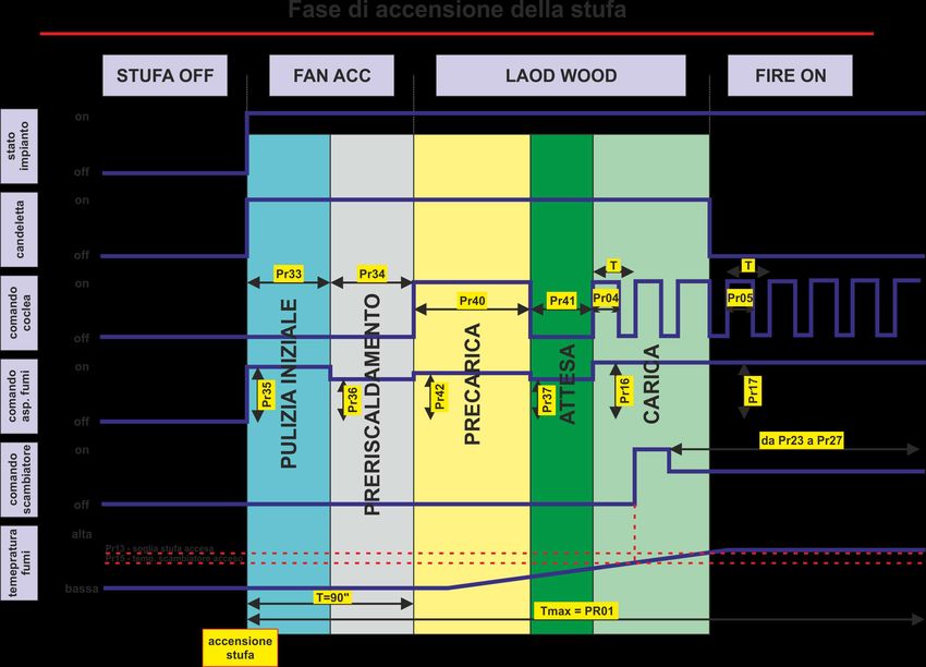
8.9 Pulizia del braciere
Durante la normale operatività nella modalità lavoro, a intervalli
stabiliti dal parametro Pr03 viene attivata la modalità “PULIZIA
BRACIERE” per la durata stabilita dal parametro Pr12.
IN LAVORO
PULIZIA
BRACIERE
fig. 21
Micronova S.r.l. - Via A. Niedda, 3 - 35010 Vigonza (PD) - +39 049 8931563 - +39 049 8931346ENG
Micronova Control board L023
date 11/06/2016
page 43 of 83
USER OPERATING MODE
OPERATING
8.8 The room temperature reaches the SET temperature STATUS
Once the room temperature reaches the set temperature or the flue
temperature has reached Pr13, the heating power is automatically
brought to the lowest point, MODULATION condition, see figure
20.
WORKING
fig. 20
SHUT DOWN
If standby mode has been activated, the stove will switch off with a
delay equal to the Pr44 time after having reached the set temperature.
The reignition will occur when the following conditions have been
met:
Tambiente > (TSET + Pr43)
8.9 Cleaning the ashpan
During normal operation in the working phase, “CLEAN ASHPAN” mode is
activated at intervals established by the Pr03 setting and for the amount of time
established by the Pr12 setting.
ASHPAN
CLEANING
WORKING
fig. 21
Micronova S.r.l. - Via A. Niedda, 3 - 35010 Vigonza (PD) - +39 049 8931563 - +39 049 8931346ITA
Micronova Controllore L023
data 11/06/2016
MODALITÀ OPERATIVA UTENTE pag. 44 di 83
STATO
OPERATIVO 8.10 Spegnimento della stufa
Per spegnere la stufa è sufficiente premere sul pulsante P4 per circa 2
secondi.
La coclea è immediatamente arrestata e l’estrattore fumi viene portato
a velocità elevata.
Viene eseguita la fase di PULIZIA FINALE.
L’attività dell’estrattore fumi è disabilitata trascorso il tempo Pr39
dopo che la temperatura fumi è scesa sotto il valore a parametro Pr28.
SPEGNIMENTO
fig. 22
8.11 Stufa spenta
.
SPENTA
fig. 23
8.12 Riaccensione della stufa
Non sarà possibile riavviare la stufa fino a che la temperatura fumi
non è scesa al di sotto del valore Pr13 e non è trascorso il tempo di
sicurezza Pr38.
RIAVVIO
fig. 24
Micronova S.r.l. - Via A. Niedda, 3 - 35010 Vigonza (PD) - +39 049 8931563 - +39 049 8931346ENG
Micronova Control board L023
date 11/06/2016
page 45 of 83
USER OPERATING MODE
OPERATING
MODE 8.10 Switching off the stove
To switch off the stove simply press the P4 button for about 2
seconds.
The auger is immediately stopped and the flue is brought to high
speed.
The FINAL CLEANING phase is carried out.
The flue is disabled once the Pr39 time has elapsed after the flue
temperature has fallen under that of the Pr28 setting.
SHUT DOWN
fig. 22
8.11 Stove in off mode
.
OFF
fig. 23
8.12 Reigniting the stove
It won’t be possible to reignite the stove until the flue temperature
falls under the temperature indicated by the Pr13 setting and a safe
amount of time has passed indicated by the Pr38 setting.
REIGNITE
fig. 24
Micronova S.r.l. - Via A. Niedda, 3 - 35010 Vigonza (PD) - +39 049 8931563 - +39 049 8931346ITA
Micronova Controllore L023
data 11/06/2016
COSA SUCCEDE SE... pag. 46 di 83
STATO
OPERATIVO
9. CHE COSA SUCCEDE SE...
9.1 Il pellet non si accende
Nel caso di mancata accensione, è visualizzato il messaggio di
allarme NO ACC come da figura 25.
ALLARME
NO FIRE
fig. 25
Agire su P4 per riportare la stufa in condizione standard.
9.2 Manca l’energia elettrica (black-out)
Pr48 = 0
Se viene a mancare la tensione di rete, al suo ripristino la stufa si
pone nello stato PULIZIA FINALE e rimane in attesa che la
temperatura fumi si abbassi fino a un valore inferiore a Pr13.
MANCANZA DI
ENERGIA
ELETTRICA
fig. 26
Pr48 = T secondi
Dopo una mancanza della tensione di rete a seconda dello stato in cui
si trovava la stufa si presentano le seguenti eventualità:
stato precedente durata black-out nuovo stato
spento qualsiasi spento
accensioneENG
Micronova Control board L023
date 11/06/2016
page 47 of 83
WHAT HAPPENS IF...
OPERATING
STATUS
9. WHAT HAPPENS IF...
9.1 The pellet does not light
In the case of lighting failure, the NO LIGHT alarm message will be
visible as illustrated in figure 25.
NO FIRE
ALARM
fig. 25
Press P4 to bring the stove back to standard condition.
9.2 There is a power outage (black out)
Pr48 = 0
If there is a power outage, when the stove turns back on, i twill go
into the FINAL CLEANING state and will wait for the flue
temperature to drop to a temperature lower than Pr13.
POWER
OUTAGE
fig. 26
Pr48 = T seconds
After a power outage, based on the state in which the stove was
before the black out, the following scenarios could take place:
previous state lenght of black out new state
off any off
lightingPuoi anche leggere