WBM Battery monitor for WESTERN WRD SYSTEM - IT EN
←
→
Trascrizione del contenuto della pagina
Se il tuo browser non visualizza correttamente la pagina, ti preghiamo di leggere il contenuto della pagina quaggiù
WBM
Battery monitor for WESTERN WRD SYSTEM

                 Manuale utente   IT
                    User manual   EN
WBM Western Battery Monitor
Manuale utente IT
MONITOR DI BATTERIA
WBM Western Battery Monitor Per batterie Pb-Flood, Pb-Seal e
LiFePO4
Tensione nominale batteria
12V, 24V o 48V
Misura corrente batteria +/-
300A precisione 0.1A.
Misura tensione di batteria
Il WBM, insieme al display WRD permettono di monitorare lo stato di carica Misura temperatura di batteria
(SOC State Of Charge) della batteria di impianti alimentati da fonti di energia
rinnovabile e implementano appositi controlli per gestire in modo oculato la Misura lo stato di carica della
batteria massimizzando la sua vita utile. Il WBM misura corrente, tensione,
temperatura della batteria e SOC, attraverso appropriati algoritmi. Questi dati batteria
vengono trasmessi al WRD che li visualizza sul display, li memorizza sul logger Uscita per controllo allarme
interno e li trasmette sul logger remoto. Il WBM può controllare la carica o la
scarica della batteria attraverso le due sue uscite di allarme. carica
Il WBM è i g ado di isu a e o e ti di atte ia ell’i te vallo di +/-300A con
elevata precisione (+/- 0.1A) e con una perdita di potenza minima (massimo Uscita per controllo allarme
9W con una corrente di 300A); per ottenere queste caratteristiche la corrente scarica
viene ricavata misurando la caduta di tensione sulla sua resistenza (shunt)
interna. Per montare correttamente il WBM nel proprio impianto si deve Interfaccia WBUS
quindi connettere la resistenza di misura interna in serie al polo negativo di
batteria. Compatibile con:
WRD
WRM60 M - SB
WRM90 M - SB
Case compatto
Fori shunt 7mm
Connessioni di segnale estraibili
1
REV 1.1 11-07-2018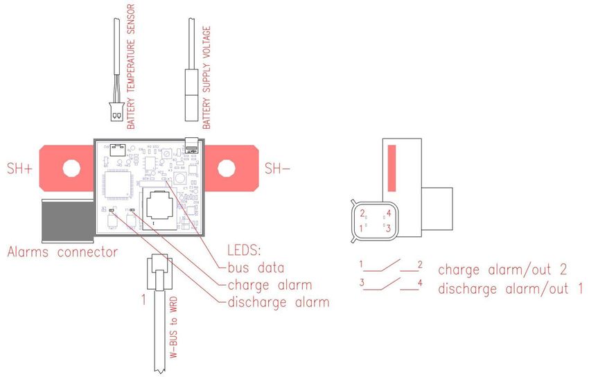
WBM Western Battery Monitor
                                                   Manuale utente                                              IT
Dettaglio connessioni

                                                 Fig.1 - Dettaglio connessioni

Segnalazioni leds:
-Led colore verde bus data: quando acceso indica che il WBM sta inviando dati verso il WRD. Nel normale
funzionamento, quando il WBM è connesso al WRD questo led lampeggia con frequenza di circa 1 secondo.
-Led colore ambra discharge alarm / out1: indica lo stato del contatto discharge alarm. Quando il led discharge alarm è
acceso il contatto è chiuso, quando è spento il contatto è aperto.
-Led colore ambra charge alarm / out2: indica lo stato del contatto charge alarm. Quando questo led è acceso il
contatto charge alarm è chiuso, quando è spento il contatto è aperto.

Connessioni:
SH+ / SH- : sono terminali della resistenza (shunt) interna al WBM per la misura della corrente di batteria. Il terminale
SH- deve essere connesso al negativo di batteria e tutte le correnti di ritorno alla batteria debbono essere connesse al
terminale SH+ (vedi Fig.2, Fig.3). Su questi terminali si possono avere correnti molto elevate (fino a +/- 300A), quindi si
debbono predisporre cavi di sezione appropriata e capicorda ad occhiello serrati con viti e dado M6 stretti con adeguate
 oppie. Si o siglia l’uso di o delle elastiche per evitare che le vibrazioni possano svitare i relativi dadi o viti. Se le
connessioni SH+ e SH- non sono adeguate alle correnti si può verificare che, du a te il fu zio a e to dell’i pia to, le
connessioni e i cavi si surriscaldano provocando la rottura del WBM o addirittura possono generare incendio o bruciare
le parti in prossimità del WBM.
BATTERY SUPPLY VOLTAGE: va collegata a questo terminale il positivo di batteria. Questa porta ha la doppia funzione di
alimentare il dispositivo WBM e quella di misurare la tensione della batteria stessa. Viene fornito in dotazione un cavo
completo di faston 2.8 mm e fusibile di protezione.
BATTERY TEMPERATURE SENSOR: va collegata la sonda di temperatura fornita in dotazione. La sonda serve a misurare
la temperatura di batteria quindi la sua zona sensibile va posizionata quanto più possibile a contatto termico con la
batteria.
W-BUS : va collegata a questa porta RJ11 la connessione dati tra il WBM e il WRD.
Alarm connector : sono presenti i due contatti di allarme per la gestione della carica e della scarica. È fornito in
dotazione un cavo completo di connettore (vedi Fig.4). Questi contatti possono essere impiegati per gestire componenti
esterni quali inverter o regolatori di carica e possono essere programmati attraverso il WRD.

                                                              2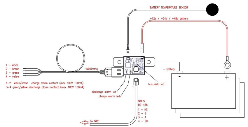
WBM Western Battery Monitor
Manuale utente IT
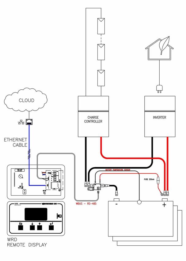
Schema di collegamento
Fig.2 - Schema di collegamento con WRD
3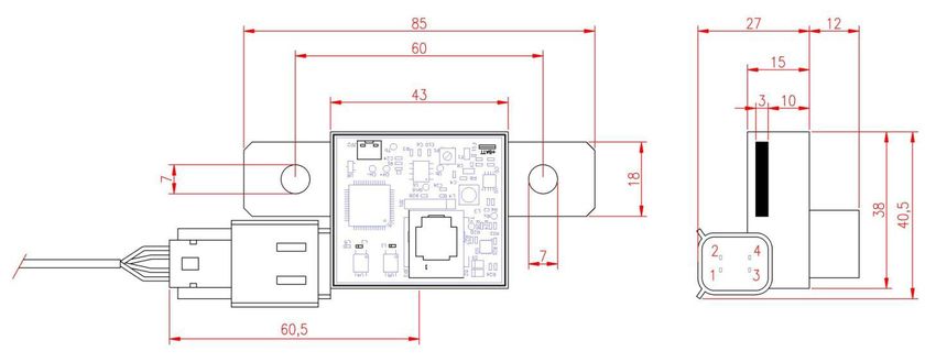
WBM Western Battery Monitor
                Manuale utente                              IT

Fig.3 - Schema di collegamento con WRM60 M - SB + WRM60 S

                           4
WBM Western Battery Monitor
                                                    Manuale utente                                                                  IT

                                            Fig.4 - Dettaglio schema di collegamento

Settaggi e programmazione
I settaggi del WBM sono eseguiti attraverso il menu 7.0 del WRD.

                                                  Valori ammessi                                       MENU 7.0
            Settings:                              Pb Flood (Batteria al Piombo acido libero)
            Batt.Type: Pb Seal/                    Pb Seal/Gel (Batteria al Piombo ermetica o gel)
                   |                               LiFePO4 (Batteria al litio tipo LiFePO4)
                   |

            B.Capacity: 200Ah                       Capacità di batteria Ah
                   |
                   |
                                                   defi is e la soglia SOC sotto la uale vie e attivato l’alla    e
            OFF disch.:↓ 20%                      discharge.
                   |
                   |
                                                    definisce la soglia SOC sopra la quale viene disattivato
            ON disch.:↑ 80%                       l’alla e dis ha ge.
                   |
                   |
                                                    defi is e la soglia SOC sop a la uale è attivata l’alla    e
            OFF charge:↑ 100%                     charge
                   |
                   |

                                                    defi is e la soglia SOC sotto la uale è disattivato l’alla   e
            ON charge:↓ 90%
                                                  charge

Settaggi:
Batt. Type: definisce il tipo di batteria e di conseguenza la tensione di carica della stessa e può essere impostato su uno
dei seguenti valori: Pb Flood, Pb Seal/Gel e 8 impostazioni LiFePO4. A seconda del tipo di batteria selezionato si
definiscono le tensioni di carica del sistema sia in fase absorption che in fase float.
Si posso o i piega e atte ie tipo P Flood o P Seal/Gel o te sio e o i ale . V, . V o . V, a l’ute te o
imposterà la tensione nominale della batteria in quanto il WBM la rileva automaticamente all’avvio. Rigua do le atte ie
LiFePO4 il sistema è compatibile solo con batterie a tensione nominale 12.6V, 25.2V e 50.4V, e anche per questo tipo di
batterie la tensione nominale è ilevata auto ati a e te dal siste a all’avvio.
             È assolutamente vietato impiegare batterie differenti ai tipi Pb Flood, Pb Seal/Gel, LifePO4 o con
             tensione nominale differente da quelle indicate in questo manuale.

                                                                5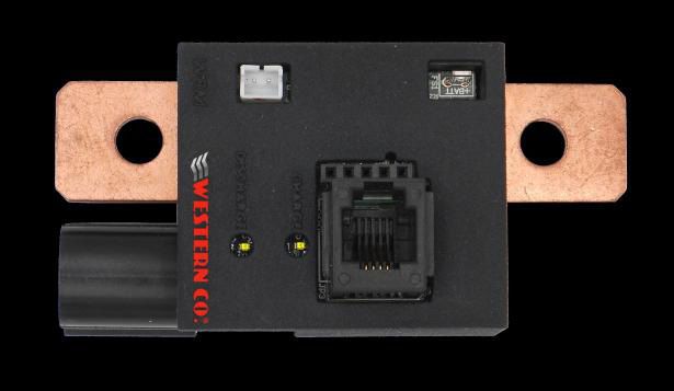
WBM Western Battery Monitor
                                                                     Manuale utente                                                              IT
Quando il WBM è impiegato insieme al WRD e ai regolatori Western CO. il WBM definisce il profilo e le tensioni di
carica della batteria. La carica è eseguita seguendo tre fasi: bulk, absorption e float :

Bulk: si impone la corrente di carica inferiore a 0.25*C per batterie al
piombo o 0.50*C per batterie LiFePO4 (C è la capacità della batteria).
Absorbtion: la tensione di batteria viene mantenuta alla tensione
VEoC (End of Charge Voltage). Il valore VEoC è diverso a seconda del
tipo di batteria selezionato e varia in funzione della temperatura.
Vedi grafici in Fig.5.
Dopo un tempo di Tabs di 4 ore in cui la batteria è consecutivamente
nello stato absorption questa viene impostata nella fase float.
Float: La tensione di batteria è mantenuta alla tensione VFLT inferiore alla tensione Absorption e riportata nei grafici in
Fig.5.

Battery Capacity: imposta la capacità di batteria. Per una corretta misura del SOC e per la limitazione in corrente nella
fase bulk è importante indicare l’esatto valore della capacità di batteria.

Programmazione allarmi:
I successivi settaggi definiscono la programmazione delle uscite allarme: discharge alarm (out 1) e charge alarm (out 2).
Le uscite hanno logica attiva aperta, significa che quando il relativo allarme è attivo il contatto è nello stato aperto,
viceversa, quando il relativo allarme è disattivo il contatto è chiuso.

OFF discharge: definisce la soglia SOC sotto la quale vie e attivato l’alla e dis ha ge.
ON discharge: defi is e la soglia SOC sop a la uale vie e disattivato l’alla e dis ha ge.

L’alla    e dis ha ge è attivo o disattivo anche quando si verifica una delle seguenti condizioni:
Condizione                 Pb Flood                 Pb Seal/Gel        LiFePO4                                                  discharge alarm / out 1
SOC                        SOC < OFF discharge                                                                                  attivo
                           SOC >= ON discharge                                                                                  disattivo
Corrente di batteria       battery Current < -B. Capacity*0.25         battery Current < B. Capacity*0.50                       attivo
                           battery Current>- B. Capacity*0.25          battery Current>- B. Capacity*0.50                       disattivo
Minimum voltage            battery Voltage < 11.0V*Ksys                battery Voltage < 12.6V*Ksys                             attivo
                           SOC > ON discharge                                                                                   disattivo
Temperature                battery Temperature< -20°C OR battery Temperature > 60°C                                             attivo
                           -20°C  OFF charge                                                                                     attivo
                           SOC < ON charge                                                                                      disattivo
Corrente di batteria       battery Current > B. Capacity*0.25          battery Current < B. Capacity*0.50                       attivo
                           battery Current < B. Capacity*0.25          battery Current < B. Capacity*0.50                       disattivo
Massima tensione           battery Voltage > chargeVoltage * 1.01                                                               attivo
                           battery Voltage < chargeVoltage                                                                      disattivo
Temperature                battery Temperature< 0°C OR battery Temperature > 45°C                                               attivo
                           0°C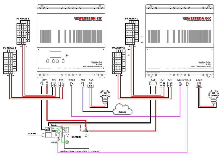
WBM Western Battery Monitor
Manuale utente IT
[V] [V]
12V BATTERY ( absorption voltage V EoC) 12V BATTERY (float voltage V FLT)
16,0 15,5
Pb Flood Pb Seal/gel Pb Flood Pb Seal/gel
15,5 15,0
15,0 14,5
14,5 14,0
14,0 13,5
13,5 13,0
-30 -20 -10 0 10 20 30 40 50 60 70 -30 -20 -10 0 10 20 30 40 50 60 70
Temperature [°C] Temperature [°C]
[V]
24V BATTERY ( absorption voltage VEoC)
[V] 24V BATTERY (float VFLT)
32,0 32,0
31,5 Pb Flood Pb Seal/gel 31,5 Pb Flood Pb Seal/gel
31,0 31,0
30,5 30,5
30,0 30,0
29,5 29,5
29,0 29,0
28,5 28,5
28,0 28,0
27,5 27,5
27,0 27,0
-30 -20 -10 0 10 20 30 40 50 60 70 -30 -20 -10 0 10 20 30 40 50 60 70
Temperature [°C] Temperature [°C]
[V] [V]
48V BATTERY ( absorption voltage VEoC) 48V BATTERY (float VFLT)
64,0 64,0
63,0 Pb Flood Pb Seal/gel 63,0 Pb Flood Pb Seal/gel
62,0 62,0
61,0 61,0
60,0 60,0
59,0 59,0
58,0 58,0
57,0 57,0
56,0 56,0
55,0 55,0
54,0 54,0
-30 -20 -10 0 10 20 30 40 50 60 70 -30 -20 -10 0 10 20 30 40 50 60 70
Temperature [°C] Temperature [°C]
[V]
[V] 12V BATTERY (absorption and float) 24V BATTERY (absorption and float)
14,9 30,0
LiFePO4 14.0V LiFePO4 28.0V
14,7 29,5
LiFePO4 14.1V LiFePO4 28.2V
14,5 LiFePO4 14.2V LiFePO4 28.6V
29,0
LiFePO4 28.6V
14,3 LiFePO4 14.3V
28,5 LiFePO4 28.8V
LiFePO4 14.4V
14,1
LiFePO4 29.0V
LiFePO4 14.5V 28,0
13,9 LiFePO4 29.2V
LiFePO4 14.6V
27,5 LiFePO4 29.4V
13,7
LiFePO4 14.7V
13,5 27,0
-30 -20 -10 0 10 20 30 40 50 60 70 -30 -20 -10 0 10 20 30 40 50 60 70
Temperature [°C] Temperature [°C]
[V]
48V BATTERY (absorption and float)
60,0
LiFePO4 56.0V
59,0
LiFePO4 56.4V
58,0 LiFePO4 56.8V
LiFePO4 57.2V
57,0
LiFePO4 57.6V
56,0 LiFePO4 58.0V
LiFePO4 58.4V
55,0
LiFePO4 58.8V
54,0
-30 -20 -10 0 10 20 30 40 50 60 70
Temperature [°C]
Fig.5 - Absorption voltage e float voltage in funzione della temperatura
7WBM Western Battery Monitor
Manuale utente IT
Dimensioni
Fig.6 - Dimensioni WBM
- Per il fissaggio sono forniti in dotazione n.2 isolatori M6: altezza 20mm, esterno 15mm.
Caratteristiche elettriche
Operating Voltage Vbat 10 V – 70.0 V
8mA @Vbat 10.0V
Operating Current Ibatt
3mA @ Vbat 60.0V
Operating Temperature Tamb -40°C – 70°C
MEASURING RANGE
Battery Current Ibat -300.0A – 300.0A
Battery Voltage Vbatt 10.0V – 70.0V
Temperature T -40°C – 90°C
State of Charge Soc 0 – 100%
RESOLUTION
Battery Current Ibat +/- 0.1A
Battery Voltage Vbatt +/- 0.01V
Temperature T +/- 0.1°C
State of Charge Soc +/- 1%
Accessories
Cable Supply Length 1,8m
Cable Alarm Length 1,8m
Cable WBUS Length 2,0m
Isolators 2 x M6, height 20mm, external 15mm
Ring Terminals 2 x 24mm2 hole 6
Screw kit M6
Tab.1 - Caratteristiche elettriche
8WBM Western Battery Monitor
Manuale utente IT
Garanzia di legge
Western CO. Srl garantisce la buona qualità e la buona costruzione dei Prodotti obbligandosi, durante il periodo di
garanzia di 5 (cinque) anni, a riparare o sostituire a sua sola discrezione, gratuitamente, quelle parti che, per cattiva
qualità del materiale o per difetto di lavorazione si dimostrassero difettose.
Il prodotto difettoso dovrà essere rispedito alla Western CO. Srl o a società delegata dalla Western CO. Srl a fare
assistenza sul prodotto, a spese del cliente, assieme ad una copia della fattura di vendita, sia per la riparazione che la
sostituzione garantita. I costi di re-installazione del materiale saranno a carico del cliente.
La Western CO. Srl sosterrà le spese di re spedizione del prodotto riparato o sostituito.
La garanzia non copre i Prodotti che, in base a nostra discrezione, risultino difettosi a causa di naturale logoramento,
che presentino guasti causati da imperizia o negligenza del cliente, da imperfetta installazione, da manomissioni o
interventi diversi dalle istruzioni da noi fornite. La garanzia decade altresì in caso di danni derivanti da:
- trasporto e/o cattiva conservazione del prodotto.
- causa di forza maggiore o eventi catastrofici (gelo per temperature inferiori a -20°C, incendio, inondazioni, fulmini, atti
va dali i, e …).
Tutte le sopraccitate garanzie sono il solo ed esclusivo accordo che soprassiede ogni altra proposta o accordo verbale o
s itto e og i alt a o u i azio e fatta t a il p odutto e e l’a ui e te i ispetto a ua to sop a.
Per qualsiasi controversia il Foro competente è Ascoli Piceno.
Smaltimento dei rifiuti
La Western CO. in qualità di produttore del dispositivo elettrico descritto nel presente manuale, ed
in conformità al D.L / / , i fo a l’a ui e te he uesto p odotto, u a volta dis esso,
deve essere consegnato ad un centro di raccolta autorizzato oppure, in caso di acquisto di
apparecchiatura equivalente può essere riconsegnato a titolo gratuito al distributore della
apparecchiatura nuova.Le sanzioni per chi abusivamente si libera di un rifiuto elettronico saranno
applicate dalle singole amministrazioni comunali.
WESTERN CO. Srl
Via Pasubio, 1
63074 San Benedetto del Tronto (AP)
tel: (+39) 0735 751248 fax: (+39) 0735 751254
e-mail: info@western.it
web: www.western.it
9WBM Western Battery Monitor
User manual EN
BATTERY MONITOR
WBM Western Battery Monitor For Pb-Flood, Pb-Seal and
LiFePO4 batteries
Nominal voltage of 12V, 24V or
48V battery
Current measurement battery
+/- 300A precision 0.1A.
Measure battery voltage
WBM, together with the WRD display let you monitor the state of charge Measure battery temperature
(SOC) of the battery of systems powered by renewable energy sources and
implements appropriate controls to manage the battery in a wise manner Measure battery state of
maximizing its useful life. WBM measures current, voltage, battery
temperature and SOC through appropriate algorithms. These data are charge
transmitted to the WRD which displays them on the display, stores them on Output for charge alarm
the internal logger and transmits them on the remote logger. WBM can control
the charge or discharge of the battery through its two alarm outputs. control
WBM is able to measure battery currents in the range of +/- 300A with high
accuracy (+/- 0.1A) and with a minimum power loss (maximum 9W with a Output for discharge alarm
current of 300A); to obtain these characteristics the current is obtained by control
measuring the voltage drop on its internal resistance (shunt). To properly
mount the WBM in your system, you must therefore connect the internal WBUS Interface
measuring resistance in series to the negative battery terminal.
Compatible with:
WRD
WRM60 M - SB
WRM90 M - SB
Compact case
7mm shunt holes
Removable signal connections
1
REV 1.1 11-07-2018WBM Western Battery Monitor
User manual EN
Connection details
Pic.1 - Connection details
LED Signalling:
-Green LED bus data: when turned on it indicates that the WBM is sending data to the WRD. In normal functioning,
when the WBM is connected to the WRD this led flashes with a frequency of about 1 second.
-Amber LED discharge alarm / out1: indicates the status of the discharge alarm contact. When the led discharge alarm
is on, the contact is closed, when it is off, the contact is open.
-Amber LED charge alarm / out2: indicates the status of the charge alarm contact. When this led is on, the charge alarm
contact is closed, when the contact is off, the contact is open.
Connections:
SH + / SH- : they are resistance terminals (shunts) inside the WBM for measuring the battery current. The SH-terminal
must be connected to the battery negative and all the return currents to the battery must be connected to the SH +
terminal (see Pic.2, Pic.3). These terminals can have very high currents (up to +/- 300A), so you must provide cables with
an appropriate cross-section and eyelet lugs tightened with tight screws and nut M6 with suitable torques. We
recommend the use of elastic washers to prevent vibrations from unscrewing the relative nuts or screws. If the SH + and
SH- connections are not adapted to the currents, might occurr that, during the system functioning, the connections and
cables overheat causing the WBM to break or even cause fire or burning of the parts near the WBM.
BATTERY SUPPLY VOLTAGE: the battery positive must be connected to this terminal. This port has the dual function of
powering the WBM device and measuring the battery voltage itself. A complete 2.8 mm faston cable and a protection
fuse are supplied.
BATTERY TEMPERATURE SENSOR: this must be connected to the supplied temperature sensor. The sensor is used to
measure the battery temperature, so its sensitive area must be positioned as much as possible in thermal contact with
the battery.
W-BUS : the data connection between the WBM and the WRD must be connected to this RJ11 port.
Alarm connector : there are two alarm contacts for charge and discharge management. A cable complete with
connector is supplied (see Pic.4). These contacts can be used to manage external components such as inverters or
charge controllers and can be programmed via the WRD.
2WBM Western Battery Monitor
User manual EN
Connection diagram
Pic.2 - Connection diagram with WRD
3WBM Western Battery Monitor
User manual EN
Pic.3 Connection diagram with WRM60 M - SB + WRM60 S
4WBM Western Battery Monitor
User manual EN
Pic.4 - Connection diagram detail
Settings and programming
The WBM settings are performed through the 7.0 menu of the WRD.
Permitted values MENU 7.0
Settings: Pb Flood (Free Lead Acid Battery)
Batt.Type: Pb Seal/ Pb Seal / Gel (Hermetic lead acid or gel)
| LiFePO4 (LiFePO4 lithium battery)
|
B.Capacity: 200Ah Battery capacity Ah
|
|
OFF disch.:↓ 20% defines the SOC threshold under which the discharge alarm is
activated.
|
|
defines the SOC threshold above which the discharge alarm is
ON disch.:↑80% deactivated.
|
|
OFF charge:↑ 100% defines the SOC threshold above which the charge alarm is
activated
|
|
ON charge:↓ 90% defines the SOC threshold below which the charge alarm is
deactivated
Settings:
Batt. Type: defines the type of battery and consequently the charging voltage of the same and can be set to one of the
following values: Pb Flood, Pb Seal / Gel and 8 settings LiFePO4. Depending on the type of battery selected, the system
charging voltages is defined both in the absorption phase and in the float phase.
Pb Flood or Pb Seal / Gel batteries can be used with nominal voltage 12.0V, 24.0V or 48.0V, but the user will not set the
nominal voltage of the battery as the WBM automatically detects it at startup. Regarding the LiFePO4 batteries, the
system is only compatible with batteries with a nominal voltage of 12.6V, 25.2V and 50.4V, and also for this type of
batteries the nominal voltage is automatically detected by the system at startup.
It is absolutely forbidden to use different types of batteries: Pb Flood, Pb Seal / Gel, LifePO4 or with a
nominal voltage different from those indicated in this manual.
5WBM Western Battery Monitor
User manual EN
When the WBM is used together with the WRD and the Western CO. controllers the WBM defines the profile and the
battery charge voltages. The charge is performed following three phases: bulk, absorption and float :
Bulk: the charge current is lower than 0.25 * C for lead batteries or
0.50 * C for LiFePO4 batteries (C is the battery capacity).
Absorbtion: the battery voltage is maintained at VEoC voltage (End
of Charge Voltage). The VEoC value is different depending on the
type of battery selected and varies according to the temperature.
See graphs in Pic.5.
After a time of Tabs is 4 hours in which the battery is consecutively in
the state of absorption this is set in the float phase.
Float: The battery voltage is maintained at VFLT voltage lower than the Absorption voltage and shown in the graphs in
Pic.5.
Battery Capacity: set the battery capacity. For a correct SOC measurement and for the current limitation in the bulk
phase it is important to indicate the exact value of the battery capacity.
Alarm programming:
The subsequent settings define the programming of the alarm outputs: discharge alarm (out 1) and charge alarm (out
2). The outputs have active logic open, it means that when the relative alarm is active the contact is in the open state,
vice versa, when the relative alarm is off, the contact is closed.
OFF discharge: defines the SOC threshold under which the discharge alarm is activated.
ON discharge: defines the SOC threshold above which the discharge alarm is deactivated.
The discharge alarm is on or off even when one of the following conditions occurs:
Condition Pb Flood Pb Seal/Gel LiFePO4 discharge alarm / out 1
SOC SOC = ON discharge deactivated
Battery current battery Current < -B. Capacity*0.25 battery Current - B. Capacity * 0.25 battery Current> - B. Capacity * 0.50 deactivated
Minimum voltage battery Voltage chargeVoltage * 1.01 activated
battery Voltage < chargeVoltage deactivated
Temperatures battery Temperature 45° C activated
0 ° CWBM Western Battery Monitor
User manual EN
[V] [V]
12V BATTERY ( absorption voltage V EoC) 12V BATTERY (float voltage V FLT)
16,0 15,5
Pb Flood Pb Seal/gel Pb Flood Pb Seal/gel
15,5 15,0
15,0 14,5
14,5 14,0
14,0 13,5
13,5 13,0
-30 -20 -10 0 10 20 30 40 50 60 70 -30 -20 -10 0 10 20 30 40 50 60 70
Temperature [°C] Temperature [°C]
[V] [V]
24V BATTERY ( absorption voltage VEoC) 24V BATTERY (float VFLT)
32,0 32,0
31,5 Pb Flood Pb Seal/gel 31,5 Pb Flood Pb Seal/gel
31,0 31,0
30,5 30,5
30,0 30,0
29,5 29,5
29,0 29,0
28,5 28,5
28,0 28,0
27,5 27,5
27,0 27,0
-30 -20 -10 0 10 20 30 40 50 60 70 -30 -20 -10 0 10 20 30 40 50 60 70
Temperature [°C] Temperature [°C]
[V] [V]
48V BATTERY ( absorption voltage VEoC) 48V BATTERY (float VFLT)
64,0 64,0
63,0 Pb Flood Pb Seal/gel 63,0 Pb Flood Pb Seal/gel
62,0 62,0
61,0 61,0
60,0 60,0
59,0 59,0
58,0 58,0
57,0 57,0
56,0 56,0
55,0 55,0
54,0 54,0
-30 -20 -10 0 10 20 30 40 50 60 70 -30 -20 -10 0 10 20 30 40 50 60 70
Temperature [°C] Temperature [°C]
[V]
[V] 12V BATTERY (absorption and float) 24V BATTERY (absorption and float)
14,9 30,0
LiFePO4 14.0V LiFePO4 28.0V
14,7 29,5
LiFePO4 14.1V LiFePO4 28.2V
14,5 LiFePO4 14.2V LiFePO4 28.6V
29,0
LiFePO4 28.6V
14,3 LiFePO4 14.3V
28,5 LiFePO4 28.8V
LiFePO4 14.4V
14,1
LiFePO4 29.0V
LiFePO4 14.5V 28,0
13,9 LiFePO4 29.2V
LiFePO4 14.6V
27,5 LiFePO4 29.4V
13,7
LiFePO4 14.7V
13,5 27,0
-30 -20 -10 0 10 20 30 40 50 60 70 -30 -20 -10 0 10 20 30 40 50 60 70
Temperature [°C] Temperature [°C]
[V]
48V BATTERY (absorption and float)
60,0
LiFePO4 56.0V
59,0
LiFePO4 56.4V
58,0 LiFePO4 56.8V
LiFePO4 57.2V
57,0
LiFePO4 57.6V
56,0 LiFePO4 58.0V
LiFePO4 58.4V
55,0
LiFePO4 58.8V
54,0
-30 -20 -10 0 10 20 30 40 50 60 70
Temperature [°C]
Pic.5 - Absorption voltage and float voltage as a function of temperature
7WBM Western Battery Monitor
User manual EN
Dimensions
Pic.6 - WBM dimensions
- For the fastening are provided no. 2 M6 insulators: height 20mm, external 15mm.
Electrical features
Operating Voltage Vbat 10 V - 70.0 V
8mA @Vbat 10.0V
Operating Current Ibatt
3mA @ Vbat 60.0V
Operating Temperature Tamb -40 ° C - 70 ° C
MEASURING RANGE
Battery Current Ibat -300.0A – 300.0A
Battery Voltage Vbatt 10.0V - 70.0V
Temperatures T -40°C – 90°C
State of Charge Soc 0 – 100%
RESOLUTION
Battery Current Ibat +/- 0.1A
Battery Voltage Vbatt +/- 0.01V
Temperatures T ± 0.1 ° C
State of Charge Soc +/- 1%
Accessories
Cable Supply Length 1.8m
Cable Alarm Length 1.8m
Cable WBUS Length 2.0m
Isolators 2 x M6, height 20mm, external 15mm
Ring Terminals 2 x 24mm2 hole 6
Screw kit M6
Tab.1 - Electrical features
8WBM Western Battery Monitor
User manual EN
WARRANTY
Western CO. Srl guarantees the good quality and good design of its own Products obliging itself, during the warranty
period of 5 (five) years, to repair or replace at its sole discretion, for free, those defective parts owing to poor quality of
material or defect in workmanship.
The defective product must be returned to Western Co. Srl or to the company delegated by Western Co to make
produ t support, at usto er’s e pe ses, together ith a op of the i oi e oth for repairing and warranty
replacement. The costs of re-installation of the equipment will be borne by the customer.
Western CO. Srl will bear the transport expenses of the repaired or replaced product.
The warranty does not cover Products that, according to our discretion, are defective due to natural wear, showing
damages caused by incompetence or negligence of the customer, imperfect installation, by tampering or other
interventions different by the instructions supplied by us. The warranty is not valid also in case of damages coming
from:
- transport and/or incorrect storage of the product.
- force majeure or catastrophic events (frost to temperatures below -20° C, fire, flood, lightning, vandalism, and so on).
All of the above mentioned guarantees are the sole and exclusive agreement which supersedes any proposal or
agreement, oral or written, and any other communication made between the manufacturer and the purchaser in
respect of the above.
For any dispute the jurisdiction is Ascoli Piceno.
Waste disposal
Western CO. as manufacturer of the electrical device herein described and in accordance with DL
07/25/2005 n 151, informs the consumer that this product, once abandoned, must be delivered to
an authorized collection centre or, in case of purchase of an equivalent equipment, it can be
returned free of charge to the distributor of the new equipment.
Western CO. Srl
Via Pasubio, 1
63074 San Benedetto del Tronto (AP)
ph: (+39) 0735 751248 fax: (+39) 0735 751254
e-mail: info@western.it
web: www.western.it
9Questo documento è di proprietà di WESTERN CO. Srl - Tutti i diritti sono riservati - La
riproduzione e l'uso delle informazioni contenute nel presente documento sono vietati senza il
consenso scritto di WESTERN CO. Srl.
This document is the property of WESTERN CO. Srl - All rights are reserved - Reproduction and
use of information contained within this document is forbidden without the written consent of
WESTERN CO. Srl.
Copyright © 2018 - Western CO. SrlPuoi anche leggere