HIGHLY EFFICIENT EVAPORATORS - FRIGOPACK
←
→
Trascrizione del contenuto della pagina
Se il tuo browser non visualizza correttamente la pagina, ti preghiamo di leggere il contenuto della pagina quaggiù

H I G H LY E F F I C I E N T E VA P O R ATO R S
e v a p o r a t o r i   a d   a l t a   e f f i c i e n z a
Abbiamo
                                              INDEX - INDICE

                                              3
                                              Great performance and efficiency

regalato
                                              at the highest level
                                              Prestazioni elevate ed efficienza
                                              ai massimi livelli

                                              4

all’acqua
                                              PE series: conuter flow evaporator
                                              Serie PE evaporatori in perfetta controcorrente

                                              5
                                              PE series main features

performance
                                              Serie PE caratteristiche

                                              6
                                              Quality and approvals
                                              Qualità ed approvazioni

straordinarie.
                                              8
                                              Suggestion for a correct application
                                              Suggerimenti per una corretta applicazione

                                              9

Stando vicini
                                              Order code - Codice ordinazione
                                              10
                                              Capacity - Potenza 230-860 kW

alla natura.                                  11
                                              Capacity - Potenza 930-2290 kW
                                              12
                                              Auxiliary connections - Connessioni ausiliarie
We push water to extraodinary performances,
standing close to nature.                     12
                                              Water connections - Connessioni acqua
                                              13
                                              Refrigerant connection
                                              Connessioni refrigerante

                                              15
                                              FME series: flooded mono-body
                                              evaporators
                                              Serie FME evaporatori allagati monocorpo

                                              16
                                              FMW series main features
                                              Serie FME caratteristiche

                                              17
                                              Approvals and working limit
                                              Approvazioni e limiti di applicazione

                                              17
                                              Auxiliary connections - Connessioni ausiliarie

                                              18
                                              Capacity - Potenza 110-1100 kW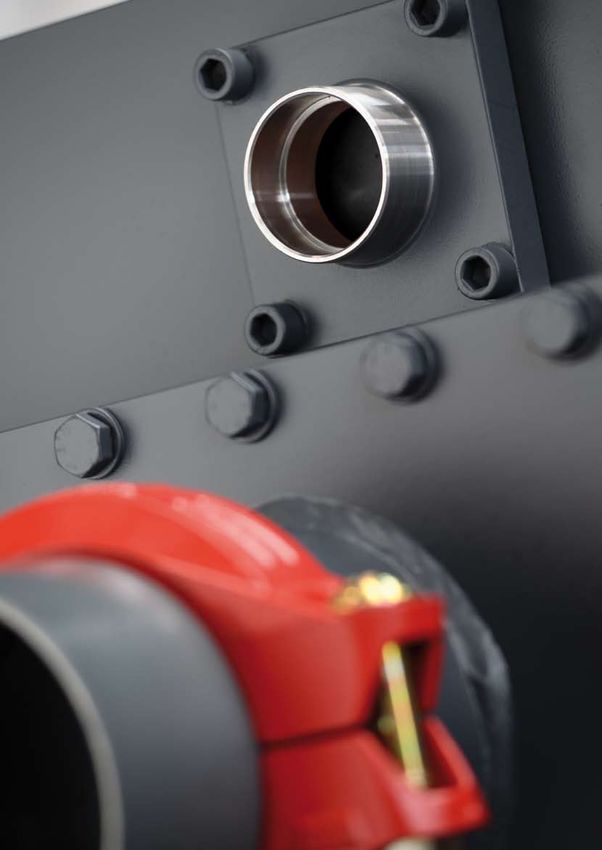
Great performance and efficiency at the highest level
                                     Prestazioni elevate ed efficienza ai massimi livelli

   WTK mission can be described as the determina-                La mission di WTK si riassume nella volontà di co-
   tion to seize the opportunities offered by the lively         gliere le opportunità di un settore vivace nelle ap-
   business field of air-conditioning and refrigera-             plicazioni del condizionamento e della refrigera-
   tion applications by focusing all efforts and atten-          zione, focalizzando sforzi e attenzione sui temi più
   tion on the subjects of great topical interest, the           attuali in primis quello del risparmio energetico.
   main one being energy saving.

   With its team of professionals prepared to answer eve-        Grazie ad una squadra di professionisti preparata per
   ry request of a rapidly evolving market, WTK is proud to      soddisfare ogni esigenza di un mercato in continua evo-
   present its latest range of highly efficient evaporators:     luzione, WTK è orgogliosa di presentare le ultime serie
   PE direct expansion evaporators                               nate di evaporatori ad alta efficienza denominate:
   FME flooded evaporators                                       PE espansione diretta
                                                                 FME tipo allagato

   These components, which are of crucial importance for
   every cooling system such as air-conditioning chillers,
   are the outcome of a Company which has always belie-
   ved in the importance of constant investments in state-
   of-the-art equipment by which it is possible to devise
   and manufacture innovative products according to the
   customers’ specific needs.

                                                                 Questi componenti fondamentali per ogni macchina fri-
                                                                 gorifera tipo chiller da condizionamento, nascono oggi
                                                                 grazie ad un’azienda che da sempre crede nell’impor-
                                                                 tanza di effettuare costanti investimenti in attrezzature
                                                                 all’avanguardia che consentono di studiare  e realizza-
                                                                 re prodotti innovativi dedicati alle specifiche esigenze
                                                                 di ogni cliente.

                                                                                                                             3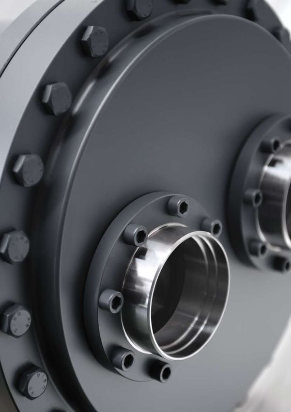
PE series: counter-flow evaporators
                                        Serie PE evaporatori in perfetta controcorrente

       PE range is revolutionary and innovative from the            La serie PE rappresenta una rivoluzione tecnologi-
       point of view of technology and construction as              ca e costruttiva che rompe gli schemi nell’evolu-
       it represents an evolution of the traditional direct         zione di una famiglia di prodotti quali gli evapora-
       expansion evaporators.                                       tori ad espansione diretta di tipo tradizionale.

                                                                    Si tratta infatti nuovi evaporatori definiti “monopasso”
                                                                    o in perfetta controcorrente che sono realizzati sfrut-
                                                                    tando schemi costruttivi e componenti di ultima gene-
                                                                    razione.

                                                                    Ottimizzati per applicazioni con gas refrigerante R134a,
                                                                    garantisco altissime performance della macchina frigori-
                                                                    fera grazie ad approcci tra la temperatura di evaporazio-
                                                                    ne e l’uscita del fluido freddo dimezzati rispetto a quanto
                                                                    e’ possibile ottenere con scambiatori di tipo forcinato.
       This kind of evaporators are called “single-pass” or
       counter-flow evaporators and are manufactured with
       the latest construction designs and components avail-
       able in the market.

       They can achieve excellent results with refrigerator
       type R134a and guarantee top performances of the
       cooling system thanks to reduced approaches between
       evaporation temperature and outlet fluid temperature,
       cut down to half as compared to those achieved by hair-
       pin evaporators.
                                                                    Il team di ricerca e sviluppo ha progettato la gamma di
       The R&D team has developed the various models of             evaporatori PE sviluppando i modelli in un ampio range di
       the PE evaporators with a wide capacity range reach-         potenza che supera i 2000 kW con un unico scambiatore
       ing over 2000 kW, by using a single heat exchanger           diviso da 1 a 3 circuiti differenti a seconda delle esigenze.
       separated by 1 to 3 independent circuits, according to
       the various needs. By means of a fully equipped test-        Grazie ad un efficiente laboratorio di prova WTK è inol-
       ing laboratory WTK can verify the actual functioning of      tre in grado di verificare il funzionamento di ogni pro-
       previously simulated products, and can assure its cus-       dotto precedentemente studiato e simulato, offrendo ai
       tomers top performances by using a software which can        propri clienti massime garanzie di resa e un software in
       reproduce and anticipate the real functioning data in dif-   grado di ripetere ed anticipare i dati di funzionamento
       ferent working conditions.                                   reali anche nelle differenti condizioni di lavoro.

4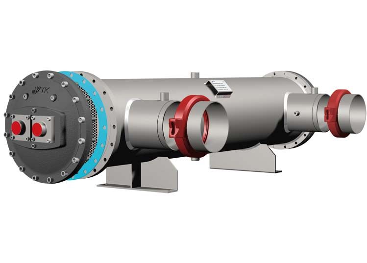
SERIE PE SERIES
main features - caratteristiche

Patented technology                                                Tecnologia brevettata
The special refrigerant distribution system which was devel-       Lo studio approfondito del sistema di distribuzione del refrige-
oped by WTK R&D team by using the latest thermodynamic             rante ad opera del team di ricerca e sviluppo di WTK che lavora
and fluid-dynamic simulation software.                             adoperando   software di ultima generazione per simulazioni
The efficiency of the distribution system is protected by a pat-   termodinamiche e fluidodinamiche accurate.
ent guaranteeing the originality and authenticity of the injec-    L’efficienza della distribuzione è per questo protetta da un
tion system of the refrigerant mixture in the gas and liquid       brevetto che garantisce l’assoluta autenticità ed unicità del
state and allowing, at the same time, the perfect suction by       sistema di iniezione della miscela di fluido allo stato gassoso e
the compressor of the refrigerant gas, without leaving any im-     liquido, permettendo nel contempo la perfetta espulsione dello
portant oil trace inside the heat exchanger.                       stesso fluido allo stato gassoso senza lasciare alcuna traccia
                                                                   importante di olio all’interno dello scambiatore.

Unattained performances                                            Performance mai raggiunte
The standard models of the PE range can reach 2300kW and           Nella serie i modelli standard raggiungono i 2300 kW   con
have a very compact size as opposed to the traditional evapo-      ingombri di spazio assai ridotti rispetto ai fasci costruiti con
rators.                                                            tecnologia tradizionale.

Respect for the environment                                        Rispetto dell’ambiente
In the same power and performance conditions, the refriger-        Le cariche di refrigerante a parità di performance e potenza
ant charges are sensibly reduced as a consequence of a more        sono assai ridotte grazie all’efficienza di scambio termico ga-
efficient heat transfer achieved by this technology.               rantite da questa nuova tecnologia.

Flexibility                                                        Flessibilità
Every model in the catalogue can be manufactured with 4 dif-       Ogni modello a catalogo può essere realizzato con 4 diverse
ferent distances between the baffles.                              distanze di setti al proprio interno. Alle tre distanze tradizio-
On top of the three traditional lengths (a standard one and        nali: standard e due ravvicinate e’ stata aggiunta una distanza
two reduced ones), a fourth and longer one was added, in           allargata, garantendo dunque sempre un ottimo compromes-
order to obtain the best compromise between water flow rate        so tra portata dell’acqua e perdite di carico.
and pressure drop.
                                                                   Facilità di installazione
Easy installation                                                  Tutti i modelli possono essere realizzati con le connessioni ac-
All models can be available with water connections in 3 dif-       qua rivolte in tre differenti posizioni.
ferent positions.
                                                                   Studio dei dettagli
Detailed study of all the components                               Sono stati progettati nei minimi particolari che possano facili-
They have been designed very carefully in order to make as-        tarne il montaggio. Sfiati a scarichi ricavati sul mantello in po-
sembly easy. Air-vents and drains are positioned in the center     sizione centrale facile da raggiungere, prese di pressione gas
of the shell to be easily reached, gas pressure connections        realizzate direttamente sulla testata, connessioni di servizio
are positioned on the front head and service connections are       applicate sui tronchetti acqua, sono solo alcuni esempi.
applied on the water pipes, to name a few examples.
                                                                   Ampia gamma di accessori
Wide range of accessories                                          Disponibili per tutti i modelli connessioni acqua con giunto fles-
Water connections with Victaulic flexible joint or, on request,    sibile victaulic o su richiesta con flangie piane, staffe di suppor-
with flat flanges, standard or reinforced support feet for the     to standard o di tipo rinforzato per l’appoggio di componenti
placement of heavy parts, such as compressors, insulation          pesanti come compressori ed altro, coibentazione realizzata
with insulating material in two different thickness (10 or 20      con materiale isolante di due spessori differenti 10 o 20mm,
mm) and sky jacket are available for all models.                   rifinito con copertina in sky.

                                                                                                                                          5
Thermal socket
                                                                                                                                              Connessione
                                                                                                                                        sonda temperatura

                                                                            Air-vents socket
                                  Head gasket                       Connessione scarico aria                                      Refrigerant outlet
                                  Guarnizione testata                                                                                   connections
         Refrigerant pressure                                                                                                    Connessioni uscita
         connections                                                                                                                    refrigerante
         Presa di pressione
         refrigerante

                                                                                                                                                            Water inlet connection
                                                                                                                                                            Connessione ingresso acqua
                                                                                               Water drain socket
                                                                                               Connessione scarico acqua
    Refrigerant inlet
    connections
                                                               Water outlet connection
    Connessioni ingresso
    refrigerante                                              Connessione uscita acqua

Quality of the materials and the processes
                                                                           Qualità dei materiali e dei processi

               Research in the design of these components was                                         La ricerca nella progettazione di questi componenti è
               aimed to guarantee high performances as well as top                                    stata indirizzata per garantire oltre alle performance
               mechanical resistance to vibrations and corrosions.                                    anche i più alti livelli di resistenza meccanica contro le
                                                                                                      vibrazioni e fenomeni di tipo corrosivo.
               For this reason the choice of the materials used is the re-
               sult of the strict quality tests carried out in compliance with                        Per questo motivo tutti i materiali utilizzati sono subordianti ai
               PED (Dir. 97/23/CE) and the European norms regulating the                              più rigidi controlli effettuati in base alla PED (Dur. 97/23/CE) e
               construction of pressure vessels.                                                      normative europee che regolano e sovrintendono alla costru-
               The typical materials of constructions are:                                            zione dei recipienti a pressione.
                                                                                                      I componenti standard sono:

               Carbon steel                                                                           Acciaio al carbonio
               header, tube sheets, shell, refrigerant and water connections                          testate, piastra tubiera, mantello e connessioni

               Pure copper                                                                            Rame puro
               tubes with a helical rifled internal surface in order to guaran-                       fasciame interno al mantello di tubi aventi una rigatura con
               tee increased surface and efficient heat exchange.                                     profilo elicoidale ottimizzato  per l’incremento di superficie
                                                                                                      ed efficienza di scambio termico.

               Intermediate baffles                                                                   Setti intermedi
               in plastic material with increased thickness, Nylon or PVC                             materiale plastico a spessore maggiorato, Nylon o PVC

               Asbestos-free gaskets                                                                  Guarnizioni
               suitable for HCFC and HFC refrigerants                                                 esenti da amianto idonee all’impiego con refrigeranti HCFC e HFC

               Alloyed steel bolts                                                                    Bulloni in acciaio legato
               fit for the temperatures generated during us                                           acciaio legato conformi alle temperature di impiego
6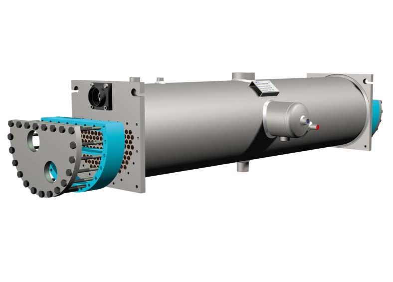
Quality system certified
                       Azienda con Sistema di Gestione Qualità certificato

   The quality of WTK heat exchangers is guaranteed                                            La qualità degli scambiatori realizzati da WTK è garantita
   throughout the whole design and production process as                                       dall’intero processo di progettazione e produttivo realizza-
   it complies with the ISO 9001 norms and is certified (as                                    to in accordo alle norme dettate dalla ISO9001 che è certi-
   is also PED) by the prestigious organization TÜV SUD.                                       ficata così come la PED dal prestigioso ente TUV SUD.

                                                                                               Tutti gli evaporatori costruiti vengono sottoposti ad un test
                                                                                               finale di collaudo per la tenuta a pressione:
   All manufactured evaporators undergo a final pressure test:                                 - Prova in pressione del lato acqua e del lato refrigerante
   - Pressure test of both water and refrigerant side                                          - Prova di pressione differenziata di ogni singolo circuito re-
   - Pressure test for each single refrigerant circuit                                           frigerante
   - Hydrostatic test with the use of a helium leakage finder                                  - Prova di tenuta con cercafughe ad elio

   After the final tests the refrigerant circuits are dried and pro-                           Al termine dei test, i circuiti refrigeranti vengono asciugati e
   tected with humidity absorbers before shipment.                                             protetti con degli assorbitori di umidità prima di essere spediti.

                                                                                         WORKING LIMITS / LIMITI D’APPLICAZIONE

                                               PED (CE)                              *L                            ASME                               GOST
                   min                             -10                               -40                              -10                               -10
   DT         °C
                   max                              90                               50                               90                                90

   Pr              Bar                             16,5                             16,5                             16,5                              16,5

   Prp             Bar                             18,2                             18,2                             18,2                              18,2

   Pw              Bar                              10                               10                               10                                10

   Pwp             Bar                              11                               11                               11                                11

   *L = Low temperature models - modelli per bassa temperatura                             Prp = Test pressure, refrigerant circuit - Pressione di prova, lato refrigerante
   DT = Design temperature - temperatura di progetto                                       Pw   = Design pressure, water circuit - Pressione di progetto lato acqua
   Pr = Design pressure, refrigerant circuit - Pressione di progetto lato refrigerante     Pwp = Test pressure, water circuit - Pressione di prova, lato acqua

                                                                                                                                                                              7
Suggestions                                                          Suggerimenti per una corretta
    for a correct application                                            selezione ed applicazione

    When choosing a shell and tube evaporator it is                      Negli evaporatori a fascio tubiero, depositi di sostanze
    necessary to account for possible deposits of sub-                   all’esterno dei tubi tra i setti sono un effetto di cui si
    stances on the outside surface of the tubes, between                 deve necessariamente tenere conto in fase di selezione
    the baffles.                                                         del prodotto.

    The fouling factor (f.f.) is therefore important in the determina-   Il fattore di sporcamento (f.f.) è quindi elemento fondamentale
    tion of the correct size of the evaporator; the right value should   per il dimensionamento corretto di un evaporatore, si suggeri-
    therefore be chosen based on the following parameters:               sce la scelta del giusto valore in base ai seguenti parametri:
    standard sweet water in closed circuit                               acqua dolce normale in circuito chiuso
    f.f. = 0.000043 m2K/W                                                f.f. = 0.000043 m2K/W
    water in open circuit                                                acqua di circuito aperto
    f.f. = 0.000086 m2K/W                                                f.f. = 0.000086 m2K/W
    solutions containing glycol < 40%                                    soluzioni contenenti glicole < 40%
    f.f. = 0.000086 m2K/W                                                f.f. = 0.000086 m2K/W
    solutions containing glycol > 40%                                    soluzioni contenenti glicole > 40%
    f.f. = 0.000172 m2K/W                                                f.f. = 0.000172 m2K/W

    A series of simple precautions must be followed to guaran-           Per una corretta applicazione degli evaporatori WTK è
    tee the proper functioning of shell and tube evaporators:            necessario rispettare alcune semplici precauzioni:

    - Avoid exceeding the maximum flow rates “Mm” which can              - Non superare le portate max “Mm” riportate a catalogo, o
      be found in the catalogue, or in the selection software, as          nel programma di calcolo, causa di eccessive vibrazioni e
      this may cause excessive vibrations and breaking of the              possibili rotture dei tubi all’interno dello scambiatore.
      tubes inside the heat exchanger.                                   - Montare l’evaporatore in posizione orizzontale in fase di
    - Install the evaporator in horizontal position .                      riempimento del circuito idrico.
    - While the water circuit is being filled, the operator must         - Fare attenzione a scaricare completamente l’aria dal circui-
      verify that absolutely no air is present in the circuit and in-      to e dall’evaporatore.
      side the evaporator.                                               - Verificare l’esistenza di un’adeguata contropressione al-
    - Make sure there is a sufficient counter pressure in the wa-          l’uscita acqua dell’evaporatore in modo da non lasciare lo
      ter outlet of the evaporator in order to avoid unloading and         scarico libero e creare quindi all’interno dell’evaporatore
      create inside pressure drop in the shell at least equivalent         stesso una perdita di carico almeno uguale a quella di ca-
      the values indicated in the catalogue or resulting from cal-         talogo o calcolo (se a circuito aperto installare all’uscita
      culations (in case of open water circuit, install a regulation       acqua una valvola di regolazione e taratura).
      valve in the water outlet) .                                       - Lasciare l’evaporatore completamente pieno d’acqua o to-
    - In case of long stops, leave the evaporator either entirely          talmente vuoto in caso di lunghe fermate, in caso di svuo-
      full or empty. Should the shell be emptied, all water must be        tamento verificare che tutto il fluido sia completamente
      completely drained. In this case absolutely no water must            drenato.
      be left in the shell.                                              - Non lasciare mai l’evaporatore parzialmente pieno evitare,
    - When using the evaporator in open circuit, do not let all            a circuito aperto, che durante la fermata della pompa l’eva-
      water flow out when the pump stops.                                  poratore si svuoti.
8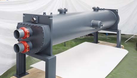
- Use only water mixed with glycol when operating with wa-                      - Evitare di operare con temperature dell’acqua prossime a 0
                        ter temperatures close to 0 °C .                                                °C, se non miscelata con glicole.
                      - Use water or inhibited brine solutions compatible with the                    - Impiegare sempre acque o soluzioni incongelabili inibite e
                        materials used, check them on a regular base and, if operat-                    compatibili con i materiali dell’evaporatore, verificarle nel
                        ing with temperatures close to the freezing point, increase                     tempo e non operare con temperature vicine al punto di
                        the brine percentages. The following table provides the re-                     congelamento, altrimenti aumentare la percentuale di an-
                        quired percentages of the main brine solutions in relation to                   ticongelante. Nella tabella sottostante troverete, in funzio-
                        the freezing point.                                                             ne del punto di congelamento, la percentuale in peso delle
                      - Analyze the water checking the compatibility with the mate-                     principali miscele anticongelanti.
                        rials of the evaporator before use.                                           - Analizzare le acque verificandone la compatibilità con i ma-
                      - Avoid the use of the evaporator with water containing chlo-                     teriali dello scambiatore prima dell’utilizzo.
                        rine (max = 3 p.p.m.)                                                         - Evitare l’uso con acque contenenti cloro (max = 3 p.p.m.).
                      - Do not reverse the water inlet and outlet in order not to                     - Non invertire l’ingresso con l’uscita dell’acqua per non pe-
                        decrease the evaporator performance or cause excessive                          nalizzare la resa o introdurre il rischio di vibrazioni eccessi-
                        vibrations inside the shell.                                                    ve del fascio interno.
                      - Do not expose the evaporator to excessive external vi-                        - Non sottoporre l’evaporatore ad eccessive vibrazioni esterne.
                        brations.                                                                     - Evitare l’ingresso di corpi estranei nel circuito idraulico.
                      - Avoid foreign particles entering the water circuit.                           - Evitare la cavitazione della pompa e la presenza di gas nel
                      - Avoid the cavitation of the pump and the presence of gas in                     circuito idraulico evitare di superare la velocità dell’acqua
                        the water circuit.                                                              consigliata (vedi programma di selezione)
                      - Do not unload the capacity (refrigerant side) more than                       - Non prevedere parzializzazioni (lato refrigerante) che scen-
                        60% of the compressor total capacity. In case of need,                          dano al di sotto del 60% della potenza totale del compres-
                        contact WTK.                                                                    sore, eventualmente contattare WTK.

                                    FREEZING POINT                                 ETHYLENE GLYCOLE                                   PROPYLENE GLYCOLE
                                PUNTO DI CONGELAMENTO                              GLICOLE ETILENICO                                  GLICOLE PROPILENE

                                            °C                                               %                                                  %
                                            -10                                             24                                                  27
                                            -20                                             36                                                  39
                                            -30                                             46                                                  49
                                            -40                                             53                                                  55

                      Order codes / Codice di ordinazione

MODEL                   NOMINAL CAPACITY           APPROVAL           BAFFLES      DESIGN TEMPERATURE          WATER CONNECTIONS           SUPPORT          ON REQUEST
MODELLO                 POTENZA NOMINALE           APPROVAZIONE       SETTI        TEMPERATURA PROGETTO        CONNESSIONI ACQUA           STAFFE           SU RICHIESTA

D       P         E      930                       C                   I           L                            D                           A               /F
                                                  _ =   without
                                                  		    senza                      _ = standard
                                                  C =   PED                                                                                                 _ =   without
                        kW                                                         L = low temperature                                                      		    senza
                        230
SHELL AND TUBE EVAPORATORS PE SERIES - CAPACITY 230 / 860 kW
FASCI TUBIERI EVAPORATORI SERIE PE - POTENZA 230 / 860 kW
SPE SPE SPE SPE SPE SPE SPE SPE SPE SPE SPE SPE
MODEL / MODELLO DPE DPE DPE DPE DPE DPE DPE DPE DPE DPE DPE DPE
230 260 300 350 370 440 490 560 630 700 800 860
NOMINAL DATA Qn kW 230 260 300 350 370 440 490 560 630 700 800 860
DATI NOMINALI
R134A Qn US Ton 65,4 73,9 85,3 99,5 105,2 125,1 139,4 159,3 179,2 199,1 227,5 244,6
T In (Brine) = 12°C
T Out (Brine) = 7°C Mn m3/h 39,7 44,9 51,8 60,4 63,9 76,0 84,6 96,7 108,8 120,9 138,2 148,5
Tev = 3°C
Tcond. = 40°C Dpn kPa 47 43 37 49 38 51 39 53 40 49 63 71
DTsh=4K - DTsb=5K
ff=0,000043m2W/K Mm m3/h 49,6 56,1 64,8 75,6 79,9 95,0 105,8 120,9 136,0 151,1 172,7 185,6
SPE II II II II II II II III III III III III
PED CATEGORY
DPE II II II II II II II II II II II II
CATEGORIA PED *
TPE / / / / / / / / / / / /
VOLUME Vr dm 3
33 38 42 44 52 58 62 73 79 87 95 100
VOLUME Vw dm3 115 109 106 103 159 153 148 261 255 247 240 234
WEIGHT / PESO kg 224 232 238 244 314 324 334 492 501 522 533 543
* PED category according to EU directive 97/23-CE. The category refers to the use of group 2 fluids at the PS value of standard temperature version
A mm 2400 2400 2350
B mm 2900 2920 2940
C mm 273 324 406
D mm 250 260 295
DIMENSIONS E mm 100 200 200
DIMENSIONI F mm 340 390 480
R mm 1800 1800 1800
S mm 50 56 56
T mm 220 240 320
U mm 100 100 100
SPE / DPE
F F D A±5 D E U
M K
d1
d3
d2
ØC
S±2
T = R =
B±15
DIAMETER F mm 340 390 480
HEAD CIRCUITS N° SPE DPE SPE DPE SPE DPE
TESTATA K mm 72 72 / 104 131 131
DIMENSIONS
DIMENSIONI M mm / 102 / 122 / 150
d1 DN 125 125 150 150 200 200
CONNECTIONS
d2 ODS 54 35 64 42 80 54
CONNESSIONI
d3 ODS 80 64 105 80 105 105
LEGENDA
Qn = Nominal capacity - Potenza nominale Mm = Maximim water flow rate - Portata acqua massima ff = Fouling factor - Fattore di sporcamento
Mn = Nominal water flow rate - Portata acqua nominale DTsh = Superheating value - Gradi di surriscaldamento Vr = Volume of refrigerant circuit - Volume lato refrigerante
Dpn = Nominal pressura drop - Perdite di carico nominali DTsb = Subcooling value - Gradi di sottoraffreddamento Vw = Volume of water circuit - Volume lato acqua
10SHELL AND TUBE EVAPORATORS PE SERIES - CAPACITY 930 / 2290 kW
FASCI TUBIERI EVAPORATORI SERIE PE - POTENZA 930 / 2290 kW
DPE DPE DPE DPE DPE DPE DPE DPE DPE DPE DPE DPE
MODEL / MODELLO TPE TPE TPE TPE TPE TPE TPE TPE TPE TPE TPE TPE
930 1000 1100 1200 1300 1400 1500 1600 1760 1960 2110 2290
NOMINAL DATA Qn kW 930 1000 1100 1200 1290 1380 1490 1610 1760 1960 2110 2290
DATI NOMINALI
R134A Qn US Ton 264,5 284,4 312,9 341,3 366,9 392,5 423,8 457,9 500,6 557,5 600,1 651,3
T In (Brine) = 12°C
T Out (Brine) = 7°C Mn m3/h 160,6 172,7 190,0 207,2 222,8 238,3 257,3 278,0 303,9 338,5 364,4 395,5
Tev = 3°C
Tcond. = 40°C Dpn kPa 39 44 53 64 50 58 67 77 58 72 83 97
DTsh=4K - DTsb=5K
ff=0,000043m2W/K Mm m3/h 201 216 237 259 278 298 322 348 380 423 455 494
SPE / / / / / / / / / / / /
PED CATEGORY
DPE II II II III III III III III III III III III
CATEGORIA PED *
TPE II II II II II II II II III III III III
Vr dm 3
116 123 131 143 152 161 172 187 213 226 241 253
VOLUME
VOLUME
Vw dm3 412 405 397 385 542 533 522 507 764 751 735 724
WEIGHT - PESO kg 734 744 756 768 864 877 893 908 1236 1256 1279 1298
* PED category according to EU directive 97/23-CE. The category refers to the use of group 2 fluids at the PS value of standard temperature version
A mm 2350 3200 3150
B mm 2950 3800 3790
C mm 508 508 610
D mm 300 300 320
DIMENSIONS E mm 200 200 200
DIMENSIONI F mm 580 580 680
R mm 1800 2500 2500
S mm 56 56 56
T mm 410 410 410
U mm 100 DPE / TPE 100 100
F F D A±5 D E U E U
M M M K K K
d1
d3
d2
ØC
S±2
T = R =
B±15
DIAMETER F mm 580 580 680
HEAD CIRCUITS N° DPE TPE DPE TPE DPE TPE
TESTATA K mm 150 132 150 132 200 175
DIMENSIONS
DIMENSIONI M mm 188 132 188 132 200 175
d1 DN 200 200 200 200 250 250
CONNECTIONS
d2 ODS 64 54 64 54 80 64
CONNESSIONI
d3 ODS 105 89 105 89 105 105
LEGENDA
Qn = Nominal capacity - Potenza nominale Mm = Maximim water flow rate - Portata acqua massima ff = Fouling factor - Fattore di sporcamento
Mn = Nominal water flow rate - Portata acqua nominale DTsh = Superheating value - Gradi di surriscaldamento Vr = Volume of refrigerant circuit - Volume lato refrigerante
Dpn = Nominal pressura drop - Perdite di carico nominali DTsb = Subcooling value - Gradi di sottoraffreddamento Vw = Volume of water circuit - Volume lato acqua
11Auxiliary connections / Connessioni ausiliarie
Water connections / Connessioni acqua
THREADED CONNECTIONS / CONNESSIONI FILETTATE
d [in] A (mm) B (mm) C (mm)
d
1” 1/2 30 25 60
B
C
A
2” 30 25 60
2” 1/2 30 35 60
3” 30 35 60
FLEXIBLE JOINT / GIUNTO FLESSIBILE
B C OD
DN OD A B C D E F G H d
(mm) (mm) (mm) (mm) (mm) (mm) (mm) (mm) (mm)
D
E F
A
100 (4”) 114.3 149.2 212.8 50.8 100 15.9 9.5 110.1 4 M12
G
d H
125 (5”) 139.7 177.8 250.8 50.8 100 15.9 9.5 135.5 4 M16
B C OD
150 (6”) 168.3 203.2 285.8 50.8 100 15.9 9.5 163.9 4 M16
D
E F
A
200 (8”) 219.1 263.5 349.3 60.3 100 19 11.1 214.4 4 M20
G
H
250 (10”) 273.0 330.2 438.8 64.3 100 19 14 268 4 M22
12Refrigerant connections / Connessioni refrigerante
ROTALOCK CONNECTIONS / ATTACCHI ROTALOCK
RT A (mm) B (mm) C (mm) ID (mm) ODS (mm)
1” - 14UNF 80 20 30 16.2 16
RT
ID
1” 1/4 - 12UNF 80 20 36 22.5 22
B
1” 3/4 - 12UNF 80 20 50 28.2 28
C A
1” 3/4 - 12UNF 80 20 50 35.3 35
WELDING CONNECTIONS / ATTACCHI A SALDARE
ODS (mm) A (mm) B (mm) ID (mm) OD (mm)
22 60 20 22.4 26.9
35 60 20 35.4 42.4
42 60 20 42.4 48.3
OD
ID
54 60 20 54.4 60.3
B
64 60 20 64.4 76.1
A
66.7 60 20 67.1 76.1
76 60 20 76.5 88.9
80 60 20 80.4 88.9
FLANGE CONNECTIONS / ATTACCHI A FLANGIA
ODS A B C D ID OD
(mm) (mm) (mm) (mm) (mm) (mm) (mm)
42 50 20 60 80 42.4 48
54 50 20 70 90 54.4 60
D
54 50 20 90 110 54.4 60
OD
ID
B 64 50 15 90 110 64.4 76
d
C
80 50 15 90 110 80.4 88.9
A
105 50 13 Ø 150 Ø 170 105.8 115
141 50 13 130 160 142 -
1314
FME series: flooded mono-body evaporators
                               Serie FME evaporatori allagati monocorpo

      Energy efficiency and unattained performances               Efficienza energetica e performance di scam-
      in the heat exchange during evaporation are the             bio termico in evaporazione mai raggiunte sono
      aims pursued in the development and realization             l’obiettivo conquistato nello sviluppo e compi-
      of this ambitious project.                                  mento di questo ambizioso progetto.

                                                                  WTK con una mirata progettazione sia di tipo tecnica
                                                                  che produttiva, è riuscita a rendere facile, flessibile e
                                                                  competitiva in ogni aspetto una tecnologia come quella
                                                                  degli evaporatori allagati, assecondando in questo modo
                                                                  le esigenze del mercato attuale e di tutti i costruttori di
                                                                  macchine frigorifere.

                                                                  L’evaporatore allagato FME e’ stato studiato principal-
                                                                  mente per il condizionamento con fluidi frigorigeni non
                                                                  azeotropi; grazie alla ricerca e sviluppo di speciali tubi
      WTK, by means of a careful technical and production
                                                                  alettati realizzati negli stabilimenti di WTK, nascono nu-
      planning, succeeded in making a technology such as
                                                                  merosi modelli che coprono un ampio range di potenze
      that of the flooded evaporators easy, flexible and com-
                                                                  in grado di assecondare ogni richiesta.
      petitive in every aspect and, in so doing, WTK has ful-
      filled the needs of today’s market and of all the cooling
      system manufacturers.

      FME flooded evaporators were devised mainly for air-
      conditioning with non-azeotropic refrigerants; following
      the research and development of special finned tubes
      manufactured in WTK workshop, many models have
      been produced with a wide power range in order to an-
      swer all needs.

      On request, it is possible to assemble IRS (Integrated
                                                                  E’ possibile montare, solo su richiesta, l’IRS (integra-
      Recovery System), a device for energy recovery inte-
                                                                  ded recovery system) ovvero un sistema di recupero
      grated in the flooded evaporator body.
                                                                  energetico integrato nel corpo stesso dell’evaporatore
                                                                  allagato.

                                                                                                                                15
SERIE FME SERIES
main features - caratteristiche
Patented technology Tecnologia brevettata
IRS is the name of the energy recovery system integrated in IRS è il nome dato al sistema di recupero energetico integra-
the heat exchanger body which, by exploiting the interaction to nel corpo dell scambiatore che sfruttando l’interazione tra
between vaporized fluid in gas state and in the liquid state fluido in fase gassosa evaporato e in fase liquida prima della
before the level control valve, guarantees the double effect of valvola di regolazione di livello, garantisce il doppio effetto
sub-cooling the condensed liquid and super-heating the gas utile di sottoraffreddamento del liquido condensato e surri-
before reaching the compressor (with a mutual isentropic scaldamento del gas prima del compressore (con un mutuo
and adiabatic heat transfer). scambio di calore isoentropico ed adiabatico).
Top performance and COP levels Performance e COP inarrivabili
thanks to the special profile of the tubes manufactured by Grazie al profilo specifico dei tubi realizzati in WTK è possibile
WTK it is possible to obtain very reduced approaches (up to ottenere approcci ridottissimi, fino a 1 / 1,5 K tra temperatu-
1/1,5K) between evaporation temperature and outlet fluid ra di evaporazione ed uscita fluido da raffreddare. In questo
temperature. As a consequence, the highest C.O.P. levels and modo si garantiscono i più alti livelli di C.O.P. ed efficienza
energy efficiency are achieved in every working condition. energetica in ogni condizione di lavoro.
Flexibility of application Flessibilità applicativa
these evaporators can be used for applications with every Evaporatori idonei ad applicazioni con qualsiasi tipo di com-
type of compressor both oil-free and screw compressors; in pressore sia oil free che a vite, nell’eventualità di compresso-
case of compressors using very viscous oils which cannot mix ri con oli particolarmente viscosi non miscibili al refrigerante,
with the refrigerant, it is advisable to mount a secondary oil consigliamo l’installazione di separatori d’olio secondari tipo
separator type RS-E which is also manufactured by WTK. RS-E sviluppati da WTK.
Flessibilità costruttiva
Flexibility of construction
Tutti gli evaporatori della serie FME con 6 diversi diametri
all FME evaporators with 6 different diameters up to 710 mm
fino a 710 mm e lunghezza tubi di 1800mm possono essere
and tube length up to 1800 mm can be manufactured with
realizzati con una lunghezza variabile a seconda delle specifi-
various lengths according to the different application needs
che esigenze applicative (+600mm, +1200mm, +1800mm).
(+600mm, +1200mm, +1800mm), in order to obtain the
Il rapporto tra le dimensioni di ingombro e condizioni di lavo-
best possible relationship between overall size and working
ro risulta quindi sempre ottimale.
conditions.
Facilità di installazione e controllo di potenza
Easy installation and capacity control Tutti i modelli sono dotati di un sistema dedicato all’alloggia-
all models can be equipped with a system for positioning the mento della sonda (non fornita) per il controllo puntuale del
level control probe (not supplied) for checking the liquid level livello di liquido e quindi della superficie di scambio utilizzata
and consequently the heat exchange surface or thermal ex- o potenza di scambio termico.
change capacity.
Studio dei dettagli
Detailed study of all the components Gli evaporatori allagati FME sono stati progettati nei minimi
FME flooded evaporators have been designed very carefully particolari che possano facilitarne il montaggio. Piastre tu-
in order to make assembly easy: square tube sheets to fix biere di forma quadrata per lo staffaggio su telai portanti di
them on supporting frames of various sizes, side service con- diversa progettazione. Connessioni di servizio laterali poste
nections on various levels to eliminate the fluid when it has a su più livelli per espulsione della miscela sempre nel punto in
higher oil content, and many others. cui è più ricca di olio. Ed altro ancora.
Wide range of special materials and customizations Ampia gamma materiali speciali e personalizzazioni
to answer special needs, it is possible to manufacture the Per le esigenze più particolari è possibile realizzare su ri-
models of this range with tubes made of Copper and Nickel chiesta i modelli di questa gamma con tubi in lega di rame e
alloys or, alternatively, of stainless steel. Other parts, such nickel o in alternativa di acciaio inox. Anche altri componenti
as headers and tube sheets, can be also made of stainless come le testate e piastre tubiere possono essere realizzati
steel. For all models it is possible to have standard or rein- in acciaio inox. Disponibili inoltre per tutti i modelli, staffe di
forced support feet for the placement of heavy parts, such as supporto standard o di tipo rinforzato per l’appoggio di com-
compressors or others. ponenti pesanti come compressori ed altro.
16Safety valve
connections
Connessioni Refrigerant outlet
valvola di sicurezza connection
Connessione uscita
IRS system refrigerante
sistema IRS
Level probe connection
Connessione sonda livello
Gasket Refrigerant inlet
connection
Guarnizione Connessione entrata
refrigerante
2/4 passes head
Testata 2/4 passaggi
WORKING LIMITS / LIMITI D’APPLICAZIONE
PED (CE) GOST
min -10 -10
DT °C
max 90 90
Pr Bar 16,5 16,5
Prp Bar 18,2 18,2
Pw Bar 10* 10*
Pwp Bar 11** 11**
Pr = Design pressure, refrigerant circuit - Pressione di progetto lato refrigerante Pw = Design pressure, water circuit - Pressione di progetto lato acqua
Prp = Test pressure, refrigerant circuit - Pressione di prova, lato refrigerante Pwp =Test pressure, water circuit - Pressione di prova, lato acqua
*16 Bar = on request - su richiesta **17,6 Bar = on request - su richiesta
Auxiliary connections / Connessioni ausiliarie
IRS system 1"NPT
(on request su richiesta) Sight glass
1/2"NPT Spia visiva
1" 16UN 2A 2 x ODS22
2 x Ø 13
17SHELL AND TUBE FLOODED EVAPORATORS FME SERIES - CAPACITY 110 / 1100 kW
EVAPORATORI ALLAGATI MONOCORPO A FASCIO TUBIERO SERIE FME - POTENZA 110 / 1100 kW
FME FME FME FME FME FME FME FME FME FME FME FME FME FME FME
MODEL / MODELLO 110 140 180 225 270 320 385 440 535 640 750 830 930 1040 1100
NOMINAL DATA Qn kW 107 139 181 224 267 320 384 437 533 640 746 831 927 1034 1109
DATI NOMINALI
R134A Qn US Ton 30 40 51 64 76 91 109 124 152 182 213 236 264 295 315
4 passi
T In (Brine) = 12°C
T Out (Brine) = 6°C Mn m3/h 15,2 19,8 25,9 32,0 38,1 45,7 54,9 62,5 76,2 91,4 106,7 118,8 132,5 147,8 158,4
Tev = 4,5°C
Tcond. = 40°C Dpn kPa 47 50 56 50 53 58 54 58 50 54 58 62 53 55 57
DTsh=1K - DTsb=5K
ff=0,000043m2W/K Mm m3/h 18 24 31 38 46 55 66 75 91 110 128 142 159 177 186
PED CATEGORY
III III III III III III IV IV IV IV IV IV IV IV IV
CATEGORIA PED *
Vr dm3 116 111 103 173 165 155 200 190 309 290 349 334 489 469 459
VOLUME
Vr cal dm3 31,5 35,7 26,6 40,0 44,7 33,4 47,0 51,2 93,3 89,7 112,6 115,2 198,0 199,2 183,4
VOLUME
Vw dm 3
16 21 27 33 40 48 57 65 79 95 111 123 138 154 162
WEIGHT - PESO kg 181 193 211 323 339 358 475 495 712 752 916 946 1144 1183 1201
* PED category according to EU directive 97/23-CE. The category refers to the use of group 2 fluids at the PS value of standard temperature version
A mm 1940 1940 1940 1950 2020 2030
C mm 324 406 457 558 610 710
D mm 230 290 380 480 510 590
H mm 350 440 500 620 670 770
DIMENSIONS
L mm 520 610 660 770 820 920
DIMENSIONI
M mm 30 30 30 40 40 40
N mm 30 30 30 40 40 40
P mm 1800 1800 1800 1800 1800 1800
X mm 350 440 500 620 670 770
2P 4P
P L
170 150
d2 50
12
DN>80
N
168
C
H
D
24
M
d1 24
d3 2x Ø13 d4
A±15 X
d1 ODS 35 42 42 54 64 80
1” NPT
IRS system sight glass
(on request d2 1/2” NPT
OD 76 spia visiva 89 114 141 2x114 2x141
su richiesta)
CONNECTIONS
CONNESSIONI d3
Gas-DN 2.1/2” 3” 100 125 125 150
(2p)
V
d4
Gas-DN 2” 2.1/2” 80 100 100 150
V
(4p)
1” 16UN 2A 2x ODS22
LEGENDA ff = Fouling factor - Fattore di sporcamento
2x Ø13
Qn = Nominal capacity - Potenza nominale Mm = Maximim water flow rate - Portata acqua massima Vr = Volume of refrigerant circuit - Volume lato refrigerante
Mn = Nominal water flow rate - Portata acqua nominale DTsh = Superheating value - Gradi di surriscaldamento Vr cal = Real volume of refrigerant charge calculated
Dpn = Nominal pressura drop - Perdite di carico nominali DTsb = Subcooling value - Gradi di sottoraffreddamento Volume calcolato di carica refrigerante reale
Vw = Volume of water circuit - Volume lato acqua
1819
WTK s.r.l. via Marconi 20 - 36045 Lonigo (VI) Italy - tel. +39 0444 727400 - fax +39 0444 727450 - www.wtk.it
                     highly efficient evaporators - release 01 - 06/2009 WTK reserves the right to modify the products contents in this catalogue without previous notice - WTK si riserva il diritto di apportare modifiche e migliorie ai prodotti a catalogo in qualsiasi momento e senza preavviso.
Puoi anche leggere