Globe Entry Urban street PV Lamp - IT EN - Western CO.
←
→
Trascrizione del contenuto della pagina
Se il tuo browser non visualizza correttamente la pagina, ti preghiamo di leggere il contenuto della pagina quaggiù

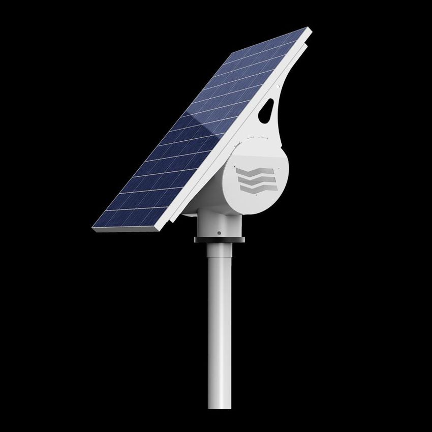
Globe Entry
Urban street PV Lamp

                  Manuale utente     IT
                       User manual   EN
GLOBE ENTRY
                                                   Manuale utente                                                IT
                                                   GLOBE ENTRY
                      LAMPIONE LED PER ARREDO URBANO A ENERGIA SOLARE

                                                                                  • LED di potenza ad alta efficienza

                                                                                   luminosa

                                                                                  • Ottica simmetrica piana o asimmetrica

                                                                                   ciclabile

                                                                                  • Apparecchio LED orientabile

                                                                                   azimutalmente

                                                                                  • LED driver a corrente costante

                                                                                  • Algoritmo di ricarica solare MPPT

                                                                                  • Modulo FV in silicio policristallino

                                                                                  • Azimut e tilt del modulo FV regolabili
GLOBE è un lampione da arredo urbano fotovoltaico stand-alone
completamente disconnesso dalla rete elettrica. Sorgente luminosa LED ad alta
                                                                              • Sistema di accumulo al Piombo
efficienza alimentata a corrente costante.
                                                                                  • Classe di isolamento elettrico III
Emissione luminosa ottimizzata per percorsi ciclopedonali ed aree verdi.
Disponibile in versione con ottica simmetrica piana o asimmetrica ciclabile. • Vano testa-palo cilindrico ispezionabile
Modulo fotovoltaico in silicio policristallino. Sistema di accumulo al Piombo a
12V.                                                                            per interventi di manutenzione

Algoritmo di ricarica MPPT del sistema di accumulo da fonte solare. Riduzione • Protezione sovraccarico,
del flusso luminoso funzione dello stato di carica della batteria. Lampione
realizzato totalmente in classe di isolamento elettrico III (SELV - sotto la soglia sovratemperatura, low-battery
della bassissima tensione).
                                                                                  • Controllo wireless opzionale

                                                                                  • Garanzia 5 anni (esclusa batteria)

                                                           1
                                                                                                            REV 1.6 17-06-2019
GLOBE ENTRY
                                                     Manuale utente                                              IT
Funzionamento
GLOBE è un lampione fotovoltaico stand-alone a LED per illuminazione urbana.
L’elettronica di controllo GLOBE-TRONIC presente all’interno del lampione svolge le funzioni di regolatore di carica
fotovoltaico e di LED driver per l’alimentazione a corrente costante dell’apparecchio di illuminazione.
Durante le ore diurne l’elettronica di controllo GLOBE -TRONIC ricarica la batteria in funzione della radiazione solare
disponibile sfruttando l’algoritmo interno MPPT.
GLOBE -TRONIC è dotato di un sistema di protezione contro l’eccessiva scarica della batteria, per salvaguardare la vita di
quest’ultima. Quando la batteria raggiunge questa soglia di scarica, il lampione entra in uno stato di Low-Battery e non
può accendersi finchè non esce da questo stato, ovvero finchè la batteria non si ricarica completamente.

GLOBE-TRONIC gestisce automaticamente l’accensione e lo spegnimento dell’apparecchio di illuminazione; al crepuscolo
(si rivela il crepuscolo quando la tensione del modulo fotovoltaico scende sotto una determinata soglia) il lampione si
accende e all’alba (si rivela il dì quando la tensione del vetro fotovoltaico sale sopra una determinata soglia) il lampione
si spegne.
Il lampione può rimanere acceso per un valore massimo di 12 ore a notte (quindi quando la durata della notte è superiore
a questo limite il lampione si spegnerà prima dell’alba).

Il lampione lavora a flusso pieno o ridotto in funzione dello stato di carica della batteria.

Tramite un pulsante è inoltre possibile selezionare, in fase di installazione, la tipologia di emissione luminosa del lampione
che può essere: simmetrica piana o asimmetrica ciclo-pedonale.

Installazione

PASSO 1 – Montaggio lampada su struttura testa-palo

Infilare il cavo della lampada all’interno del cilindro (1). Inserire la lampada nel raccordo testa-palo a battuta con il tubo
circolare di diametro superiore ed effettuare il suo bloccaggio serrando le 3 viti M4 nascoste all’interno del corpo lampada
(2).

                                                                                 TABELLA VITERIA E BULLONERIA
                                                                          Q.tà   Descrizione
                                                                           3     VITE UNI 7687 DIN 7985 M4X20 INOX

                            1

                        2
                                                         2

                            2

                                                               2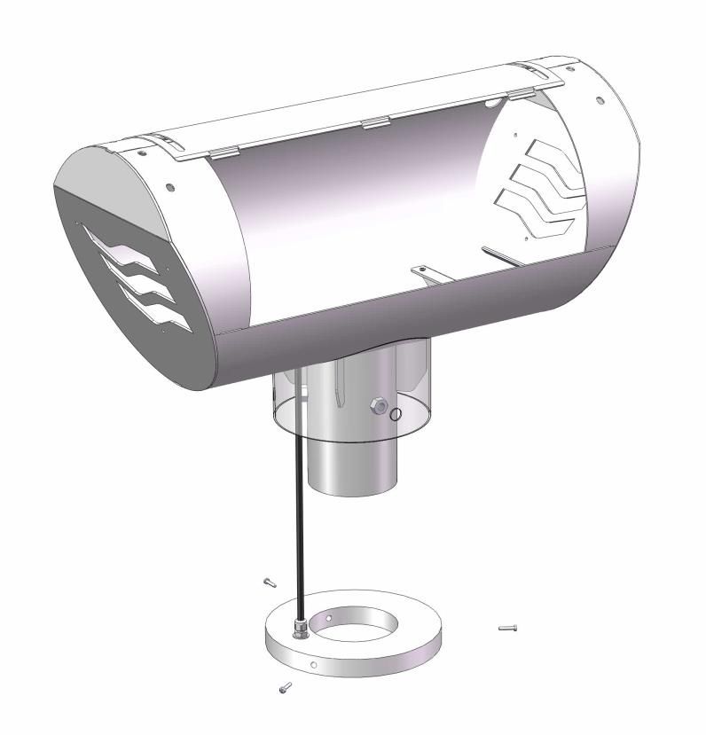
GLOBE ENTRY
                                                     Manuale utente                                              IT
PASSO 2 - Montaggio staffe di fissaggio del modulo FV

Montare le staffe di fissaggio del modulo FV al vano cilindrico. In base a tale montaggio si definisce l’inclinazione del
modulo FV. Gli angoli di inclinazione impostabili sono: 25° e 50°. Per installazioni in Italia ed in Europa impostare tilt del
modulo a 50°. Per tutte le altre località di installazione contattare l’azienda per conoscere il tilt adeguato.

                           TILT 25°                                                       TILT 50°

                                               TABELLA VITERIA E BULLONERIA
                             Q.tà     Descrizione
                               6      VITE TEIF UNI 5739 M8X20 INOX A2
                              12      RONDELLA LARGA UNI 6593 M8 INOX A2
                               6      DADO UNI 5588 M8 INOX A2

                                                              3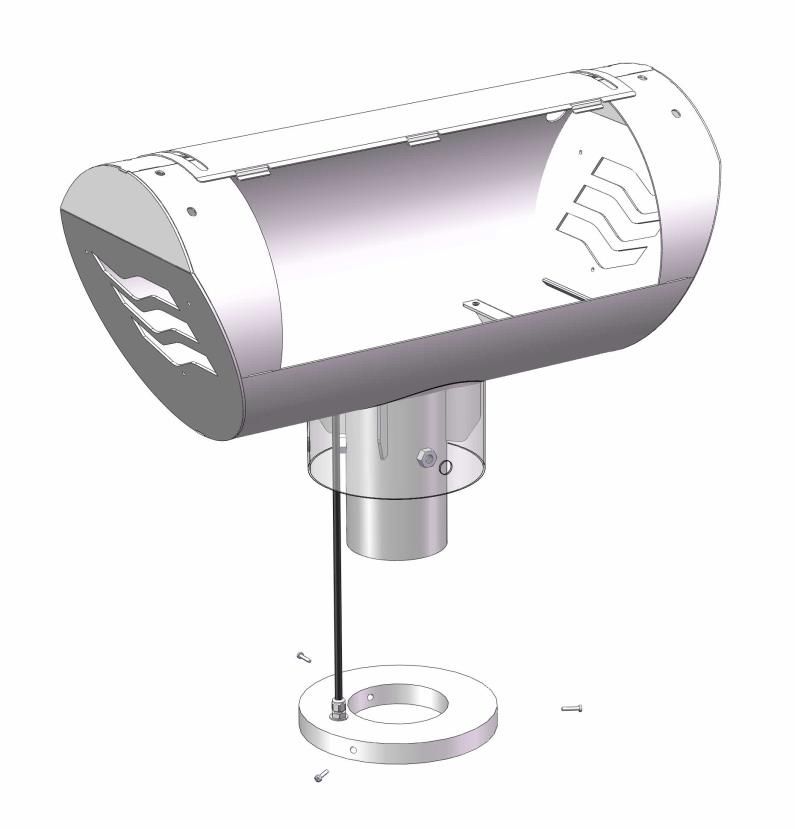
GLOBE ENTRY
                                                     Manuale utente                                                IT
PASSO 3 – Montaggio modulo FV

Montare il modulo FV alle staffe tramite apposita viteria e bulloneria avendo cura di individuare i 4 fori corretti presenti
sulle staffe in base al modulo FV ed ai suoi fori riportati sulla cornice, in modo che lo stesso rimanga centrato con le staffe.

                                                TABELLA VITERIA E BULLONERIA
                             Q.tà    Descrizione
                              4      VITE TEIF UNI 5739 M6X20 INOX A2
                              8      RONDELLA LARGA UNI 6593 M6 INOX A2
                              4      DADO AUTOBL. UNI 7473 M6 INOX A2

                                                               4
GLOBE ENTRY
                                                    Manuale utente                                             IT
PASSO 4 – Montaggio su palo

Infilare la struttura assemblata in testa al palo (1) che deve avere un diametro di testa di 102mm. Ruotare ed orientare la
struttura azimutalmente in modo che il modulo FV sia rivolto verso SUD (in caso di installazione in località dell’emisfero
NORD) o verso NORD (in caso di installazione in località dell’emisfero SUD) (2). Bloccare la struttura al palo serrando i 3
grani presenti sulla parte di raccordo testa-palo (3).

                                                                                                2
                                                                           3
                                          3
                                                                               3

                                                1

                                               TABELLA VITERIA E BULLONERIA
                            Q.tà   Descrizione
                             3     GRANO E.I.E.P. UNI 5923 M12X25 INOX A2

                                                            5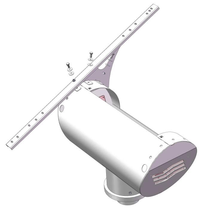
GLOBE ENTRY
                                                   Manuale utente                                            IT

PASSO 5 – Orientamento apparecchio di illuminazione

Orientare in maniera opportuna l’apparecchio di illuminazione, in funzione della tipologia di installazione e di ambiente
da illuminare.
Allentare le 3 viti M4 nascoste all’interno del corpo lampada (1), effettuare la regolazione semplicemente ruotando il
corpo (2) e infine serrare le 3 viti (3).

                                                                                              1
                                               3
                                   1                                               3

                                                        3
                                              1

                                                                              2

                                               TABELLA VITERIA E BULLONERIA
                           Q.tà    Descrizione
                            3      VITE UNI 7687 DIN 7985 M4X20 INOX

                                                            6
GLOBE ENTRY
                                                     Manuale utente                                                IT
PASSO 6 – Montaggio ripiano porta-cablaggio

Montare sul ripiano porta-cablaggio il GLOBE TRONIC a incastro tra due pieghe con il lato della scatola con i passacavo in
verticale ed il lato con il pulsante verso l’alto.
Montare il ripiano porta-cablaggio assemblato all’interno del cilindro tramite 4 viti svasate M5 in appoggio alle 2 costole
presenti sul fondo del vano cilindrico. Prima di avvitare il ripiano avere cura del passaggio del cavo lampada sotto lo stesso
e portare lo stesso cavo sopra il ripiano in prossimità del GLOBE TRONIC. Effettuare cablaggio elettrico secondo lo schema
riportato a pag. 14. Per il cablaggio del modulo FV uscire con il cavo dal vano cilindrico sfruttando il foro evidenziato in
azzurro al Passo 2 (pag. 4), salire con il cavo nascondendolo sotto la staffa reggi-modulo FV e fissandolo alla stessa tramite
fascette. Arrivare fino al culmine della staffa e curvare il cavo verso la junction box del modulo FV ed effettuare il cablaggio
al suo interno rispettando le polarità (rosso => polo positivo, nero => polo negativo).

                                                                                   GLOBE
                                                                                   TRONIC

                                                               7
GLOBE ENTRY
                                                     Manuale utente                                              IT
PASSO 7 – Montaggio batteria

Inserire la batteria all’interno del vano cilindrico ed effettuare il cablaggio con i due cavi presenti (rosso e nero) uscenti
dal GLOBE-TRONIC e dotati di capicorda ad occhiello rispettando le polarità (rosso => polo positivo, nero => polo negativo)
e serrando opportunamente le viti. Tenere lo sportello aperto.

                                                              8
GLOBE ENTRY
Manuale utente IT
PASSO 8 – Configurazione emissione luminosa
Su una delle pareti della scatola del GLOBE-TRONIC c’è installato un pulsante da pannello.
E’ possibile impostare l’ottica del lampione, agendo direttamente sull’accensione/spegnimento di uno dei due moduli LED
presenti all’interno della lampada LED.
Pulsante ON (premuto) => OTTICA SIMMETRICA PIANA 360° (tutti i LED sono accesi)
Pulsante OFF (rilasciato) => OTTICA ASIMMETRICA CICLABILE 180°(metà dei LED sono accesi)
9GLOBE ENTRY
Manuale utente IT
PASSO 9 – Collaudo e chiusura
Procedere al collaudo di giorno seguendo in ordine i seguenti passi:
1) Con il modulo fotovoltaico esposto al sole, verificare che GLOBE-TRONIC ricarichi la batteria osservando il suo LED
Verde che indica l’intensità di corrente di ricarica della batteria (IBATT) (vedi paragrafo Visualizzazioni e
protezioni) e che il lampione rimanga spento.
2) Simulare la notte scollegando temporaneamente uno dei cavi del modulo FV.
3) Verificare l’accensione del lampione e del LED Giallo su GLOBE-TRONIC (vedi paragrafo Visualizzazioni e
protezioni).
4) Testare la funzionalità del pulsante per la configurazione dell’emissione luminosa del lampione. Se il pulsante è in
posizione ON verificare l’accensione di tutti i LED presenti all’interno dell’apparecchio di illuminazione. Se è in
posizione OFF verificare l’accensione della metà dei LED.
5) Ricollegare il polo del modulo FV che era stato scollegato ed attendere lo spegnimento del lampione.
6) Verificare lo stato del LED Rosso del GLOBE-TRONIC (vedi paragrafo Visualizzazioni e protezioni). Se non ci sono
anomalie e se il banco di accumulo non è scarico, il LED Rosso deve rimanere spento.
7) Se si verifica qualche malfunzionamento contattare l’assistenza tecnica di Western CO, altrimenti richiudere lo
sportello e serrare le due viti per completare l’installazione.
TABELLA VITERIA E BULLONERIA
Q.tà Descrizione
2 VITE TBEI ISO 7380 M8X10 INOX A2
2 RONDELLA UNI 6592 M8 INOX A2
10GLOBE ENTRY
Manuale utente IT
Visualizzazioni e protezioni
Aprendo il cilindro è possibile controllare lo stato di funzionamento del lampione attraverso i LED di segnalazione del
GLOBE-TRONIC.
La seguente tabella spiega il significato dei lampeggi e delle accensioni di tali LED.
Led VERDE Funzionalità Il numero di lampeggi effettuati indica l’intensità di
corrente di ricarica della batteria – IBATT [A]
1 flash con pausa di 4,3 sec.: 0,5A < PV current < 1,5°
2 flash con pausa di 4,3 sec.: 1,5A < PV current < 2,5°
e cosi via…
.
. …valori intermedi…
.
13 flash con pausa di 4,3 sec.: 12,5A < PV current <
13,5A
Led ROSSO Funzionalità Indica lo stato del sistema
11GLOBE ENTRY
Manuale utente IT
1 flash ogni 2,2 secondi: protezione di Low-Battery
attiva; carico disattivato; occorre attendere che il
modulo PV ricarichi la batteria dopodiché la
protezione si disattiva. (condizione di normale
funzionamento)
2 flash ogni 2,2 secondi: protezione di sovraccarico
attiva; carico disattivato; dopo circa due minuti si
autoripristina esegue tre tentativi in sequenza
dopodiché aspetterà la notte successiva per
riprovare.
3 flash ogni 2,2 secondi: protezione di
sovratemperatura; carico disattivo e circuito di
ricarica disattivato; occorre attendere che la
temperatura interna al contenitore diminuisca
dopodiché la protezione si disattiva.
4 flash ogni 2,2 secondi: protezione di sovratensione;
circuito di ricarica disattivato; la protezione si
disattiverà quando la tensione di batteria rientra nel
range operativo.
Led GIALLO Funzionalità Indica lo stato del carico
CARICO SPENTO
LED giallo spento
CARICO ACCESO A FLUSSO LUMINOSO PIENO
LED giallo acceso
CARICO ACCESO A FLUSSO LUMINOSO RIDOTTO
LED giallo lampeggiante
12GLOBE ENTRY
Manuale utente IT
Schema cablaggio interno
Aprendo il cilindro è possibile controllare e verificare il cablaggio elettrico interno del lampione tra l’elettronica GLOBE-
TRONIC (elemento centrale del sistema) e tutti i componenti del lampione. Segue un’immagine rappresentativa di tale
cablaggio.
Dimensioni
13GLOBE ENTRY
Manuale utente IT
Garanzia di legge
Western CO. Srl garantisce la buona qualità e la buona costruzione dei Prodotti obbligandosi, durante il periodo di garanzia
di 5 (cinque) anni, a riparare o sostituire a sua sola discrezione, gratuitamente, quelle parti che, per cattiva qualità del
materiale o per difetto di lavorazione si dimostrassero difettose.
Il prodotto difettoso dovrà essere rispedito alla Western CO. Srl o a società delegata dalla Western CO. Srl a fare assistenza
sul prodotto, a spese del cliente, assieme ad una copia della fattura di vendita, sia per la riparazione che la sostituzione
garantita. I costi di re-installazione del materiale saranno a carico del cliente.
La Western CO. Srl sosterrà le spese di re spedizione del prodotto riparato o sostituito.
La garanzia non copre i Prodotti che, in base a nostra discrezione, risultino difettosi a causa di naturale logoramento, che
presentino guasti causati da imperizia o negligenza del cliente, da imperfetta installazione, da manomissioni o interventi
diversi dalle istruzioni da noi fornite.
La garanzia decade altresì in caso di danni derivanti da:
-trasporto e/o cattiva conservazione del prodotto.
-causa di forza maggiore o eventi catastrofici (gelo, incendio, inondazioni, fulmini, atti vandalici, ecc.).
Tutte le sopraccitate garanzie sono il solo ed esclusivo accordo che soprassiede ogni altra proposta o accordo verbale o
scritto e ogni altra comunicazione fatta tra il produttore e l’acquirente in rispetto a quanto sopra.
Per qualsiasi controversia il Foro competente è Ascoli Piceno.
Per maggiori informazioni visitare il sito: https://www.western.it/garanzia/
Smaltimento dei rifiuti
La Western CO. in qualità di produttore del dispositivo elettrico descritto nel presente manuale,
ed in conformità al D.L 25/07/05 n 151, informa l’acquirente che questo prodotto, una volta
dismesso, deve essere consegnato ad un centro di raccolta autorizzato oppure, in caso di acquisto
di apparecchiatura equivalente può essere riconsegnato a titolo gratuito al distributore della
apparecchiatura nuova. Le sanzioni per chi abusivamente si libera di un rifiuto elettronico saranno
applicate dalle singole amministrazioni comunali.
WESTERN CO. Srl
Via Pasubio, 1
63074 San Benedetto del Tronto (AP)
tel: (+39) 0735 751248 fax: (+39) 0735 751254
e-mail: info@western.it
web: www.western.it
14GLOBE ENTRY
Manuale utente EN
GLOBE ENTRY
PV LED STREETLAMP FOR STREET FURNITURE
• High efficiency power LEDs
• High efficiency power LEDs
• Asymmetrical or flat symmetrical optic
• Adjustable LED luminaire according to
azimuth
• Constant current LED driver
• MPPT charge regulator
• Poly-cristalline Silicon PV module
• Adjustable azimuth and tilt angle of PV
module
GLOBE is a PV streetlamp for street furniture stand-alone type so fully
• AGM lead battery
disconnected from the electricity grid. The LED light source has high efficiency
supplied at CC. • Electrical insulation class III
The light output is optimized for pedestrian paths and green areas. Globe is • Cylindrical top-pole box that can be
available in two versions with flat symmetrical or cycle asymmetrical optic.
Polycrystalline silicon PV module and lead AGM battery at 12V. opened for maintenance
The PV kit uses the MPPT charging algorithm of the battery from solar source. • Overload, over-temperature, low-
There is also the possibility of reduction of the luminous flux according to the
charge status of the battery. battery protection
The streetlamp is made entirely in electrical insulation class III (SELV - below the
• Optional wireless control
threshold of very low voltage).
• 5-year warranty (battery excluded)
1
REV 1.6 17-06-2019GLOBE ENTRY
User manual EN
Working principles
GLOBE is a stand-alone PV LED streetlight for urban lighting.
The GLOBE-TRONIC control electronics inside the streetlamp performs the functions of the PV charge controller and LED
driver for the constant current supply of the lighting luminaire.
During daytime the GLOBE -TRONIC control electronics recharges the battery according to the solar radiation available
and exploiting the internal MPPT algorithm.
GLOBE -TRONIC is equipped with a protection system against excessive discharge of the battery to protect its working life.
When the battery reaches this threshold low, the streetlamp is into a state of Low-Battery and does not turn on when is
in this state, that is until the battery is fully recharged.
GLOBE-TRONIC manages automatically the switching on and off of the luminaire: at sunset (it turns sunset when the
generator voltage drops below a certain threshold) the PV streetlight is on and at dawn (it turns the day when the voltage
of the PV glass rises above a certain threshold) the PV streetlight is off.
The streetlight can remain powered on for at least 12h at night (this means that when the night lasts for a longer period,
the streetlight switch off before dawn).
The streetlight works at full or reduced flux according to the charge status of the battery
Moreover, is possible to select during installation the luminous emission of the streetlight that can be flat symmetrical or
cycle-pedestrian asymmetrical.
Installation
STEP 1 – Luminaire assembly on top-of-pole structure
Insert the cable of the luminaire inside the cylinder (1). Then insert the luminaire in the connection until it snugs with the
circular tube with larger diameter and fasten it clamping no.3 M4 screws hidden inside the luminaire holder.
SCREWS AND BOLTS TABLE
Q.ty Description
3 INOX SCREW UNI 7687 DIN 7985 M4X20
1
2
2
2
2GLOBE ENTRY
User manual EN
STEP 2 – Assembly of PV module fixing brackets
Assemble the PV module fixing brackets on the cylindrical box. According to this assembly is defined the tilt of the PV
module.
Settable tilt angles are 25° and 50°. For installations in Italy and Europe set the tilt module at 50°. For all the other
Countries please contact the manufacturer to have the most appropriate tilt.
TILT 25° TILT 50°
SCREWS AND BOLTS TABLE
Q.ty Description
6 SCREW TEIF UNI 5739 M8X20 INOX A2
12 WIDE WASHER UNI 6593 M8 INOX A2
6 NUT UNI 5588 M8 INOX A2
3GLOBE ENTRY
User manual EN
STEP 3 – PV module assembly
Assemble the PV module on brackets through adequate screws and bolts being sure to identify the 4 proper holes on
brackets according to the PV module and its holes on the frame. In this way the PV module have to be centered on
brackets.
SCREWS AND BOLTS TABLE
Q.ty Description
4 SCREW TEIF UNI 5739 M6X20 INOX A2
8 WIDE WASHER UNI 6593 M6 INOX A2
4 SELF-LOCKING NUT UNI 7473 M6 INOX A2
4GLOBE ENTRY
User manual EN
STEP 4 – Assembly of the head pole structure
Insert the head pole structure with the already assembled PV in the head-pole (1) that must have a diameter of 102mm.
Once inserted, rotate the structure and turn it for the correct Azimuth configuration so that the PV module is South facing
(in case of installation in a location in the northern hemisphere or toward North (when installed in a location in the
southern hemisphere) (2). Block the structure to the pole by tightening the 3 grains on the pole head fitting (3).
2
3
3
3
1
SCREWS AND BOLTS TABLE
Q.ty Description
3 GRAIN E.I.E.P. UNI 5923 M12X25 INOX A2
5GLOBE ENTRY
User manual EN
STEP 5 – Lighting fixture orientation
Orient appropriately the luminaire, depending on the type of installation and to the environment to be lighted up.
Loosen the 3 M4 screws hidden inside the lamp (1), make the adjustment simply rotating the luminaire (2) and tighten
the three screws (3).
1
3
1 3
3
1
2
SCREWS AND BOLTS TABLE
Q.ty Description
3 SCREW UNI 7687 DIN 7985 M4X20 INOX
6GLOBE ENTRY
User manual EN
STEP 6 – Assembly of the cable holder plate
Assemble on the cable holder plate the GLOBE TRONIC fitted between two folds with the box side with vertical cable
glands and the side with the botton facing upwards.
Assemble the pre-mounted cable holder plate inside the cylinder using 4 M5 countersunk screws lying flat to the 2 clamps
at the bottom of the cylindrical box. Before tightening the plate pay attention on the proper position of the cables under
it and then keep them on the plate in proximity of the GLOBE TRONIC. Carry out electrical wiring according to the scheme
reported at page 14. For the wiring of the PV module use the cable from the cylindrical box through the hole highlighted
in blue at Step 2 (page 19), keep the cable up and hide it under the PV module support kit and then tighten to it through
clamps.
Reach the far end of the support and bend the cable toward the PV module junction box and then carry out the wiring
within complying with polarity (red → positive pole, black → negative pole).
GLOBE
TRONIC
7GLOBE ENTRY
User manual EN
STEP 7 – Battery assembly
Insert the battery and install it on the side on which there are the terminals facing upwards. Make the wiring of the battery
with the two cables included (red and black) coming out from the GLOBE-TRONIC and with eyelet terminals following the
exact polarity (red => positive pole, black => negative pole) and tighten the screws properly. Keep the door open.
8GLOBE ENTRY
User manual EN
STEP 8 – Setting of the light emission
On one side of the GLOBE-TRONIC box there is installed a switch connected to the module.
It is possible to set the optic of the streetlight operating directly on the switch on and off of one of the two LED modules
inside the LED luminaires.
Switch ON (pressed down) → FLAT SYMMETRICAL OPTIC 360° (all LED switched on)
Switch OFF (pushed upwards) → ASYMMETRICAL OPTIC 180° (half of LED switched on)
9GLOBE ENTRY
User manual EN
STEP 9 – Test and closing procedure
Proceed during the day with test following these steps:
1) With the PV module exposed to the sun, verify that the GLOBE-TRONIC recharges the battery keeping an eye on
the Green LED that indicates the intensity of the battery recharge current (IBATT) (see paragraph Displays and
protections) and tat the streetlamp is turned off.
2) Simulate the night disconnecting one of the wire of the PV module.
3) Verify the correctness of the turning on of the load and of the Yellow LED on the GLOBE-TRONIC (see paragraph
Displays and protections).
4) Test the functionality of the button for the settings LED luminaire. If the button is in ON position, verify that all
the LEDs inside the luminaire holder are turned on. If in OFF position, verify the lighting up of the half of the LEDs.
5) Reconnect the pole of the PV module that was disconnected and wait for the switch off of the streetlight.
6) Verify the status of Red LED of the GLOBE-TRONIC (see paragraph Displays and protections). If there aren’t
technical faults and if the battery isn’t discharged, the Red LED should remain off.
7) In case of malfunction we recommend to contact Western CO. Service dept. if everything is OK, close the cover
so to complete installation.
SCREWS AND BOLTS TABLE
Q.ty Description
2 SCREW TBEI ISO 7380 M8X10 INOX A2
2 WASHER UNI 6592 M8 INOX A2
10GLOBE ENTRY
User manual EN
Displays and protections
If you open the cylindrical top-of-pole, you can easily check the working principles of the streetlight through the warning
LEDs of the GLOBE-TRONIC.
In the following table there are the meanings of the flashings and lightings of those LEDs.
GREEN Led Functionalities The number of flashings indicate the current intensity of the
battery recharge – IBATT [A]
1 flash with 4.3 sec. pause: 0,5A < PV current < 1,5°
2 flashes with 4.3 sec. pause: 1,5A < PV current < 2,5°
and so on…
.
. …intermediate values…
.
13 flashes with 4.3 sec. pause: 12,5A < PV current <
13,5A
RED Led Functionalities Indicate the status of the system
11GLOBE ENTRY
User manual EN
1 flash every 2.2 sec.: Low-Battery protection
activated; load deactivated; it is necessary to wait for
the PV module to recharge the battery and then the
protection is deactivated. (standard working
condition)
2 flashes every 2.2 sec.: overload protection
activated; load deactivated; after about 2 min. it
restart itself and runs three attempts in sequence and
then you have to wait the next nighttime to try again.
3 flashes every 2.2 sec.: over temperature protection;
load deactivated and recharge circuit deactivated; it
is necessary to wait for the decrease of the inner
temperature of the box and then the protection will
be deactivated.
4 flashes every 2.2 sec: overvoltage protection;
recharge circuit deactivated; protection will be
deactivated when the battery tension return in its
working range.
YELLOW Led Functionalities Indicates the status of the load
LOAD OFF
Yellow LED off
LOAD ON AT FULL LUMINOUS FLUX
Yellow LED on
LOAD ON AT REDUCED LUMINOUS FLUX
Flashing Yellow LED
12GLOBE ENTRY
User manual EN
Inner wiring scheme
If you open the cylindrical top-of-pole, you can easily check the inner electric wirings of the streetlight between the
GLOBE-TRONIC control unit (the core of the system) and all the other components of the streetlamp. In the following
picture there is the representation of such wirings.
Dimensions
13GLOBE ENTRY
User manual EN
Warranty
Western CO. Srl guarantees the good quality and good design of its own Products obliging itself, during the warranty
period of 5 (five) years, to repair or replace at its sole discretion, for free, those defective parts owing to poor quality of
material or defect in workmanship. The defective product must be returned to Western CO. Srl or to the company
delegated by Western CO. to make product support, at customer’s expenses, together with a copy of the invoice both for
repairing and warranty replacement. The costs of re-installation of the equipment will be borne by the customer. Western
CO. Srl will bear the transport expenses of the repaired or replaced product. The warranty does not cover Products that,
according to our discretion, are defective due to natural wear, showing damages caused by incompetence or negligence
of the customer, imperfect installation, by tampering or other interventions different by the instructions supplied by us.
The warranty is not valid also in case of damages coming from: - transport and/or incorrect storage of the product. - force
majeure or catastrophic events (frost, fire, flood, lightning, vandalism, and so on). All of the abovementioned guarantees
are the sole and exclusive agreement which supersedes any proposal or agreement, oral or written, and any other
communication made between the manufacturer and the purchaser in respect of the above. For any dispute the
jurisdiction is Ascoli Piceno.
For more information visit: https://www.western.it/en/warranty/
Waste disposal
Western CO. as manufacturer of the electrical device herein described and in accordance with DL
07/25/2005 n 151, informs the consumer that this product, once abandoned, must be delivered to
an authorized collection centre or, in case of purchase of an equivalent equipment, it can be
returned free of charge to the distributor of the new equipment. The penalties will be applied by
individual Municipalities.
WESTERN CO. Srl
Via Pasubio, 1
63074 San Benedetto del Tronto (AP) - Italy
phone: (+39) 0735 751248 fax: (+ 39) 0735 751254
e-mail: info@western.it
web: www.western.it
14Questo documento è di proprietà di WESTERN CO. Srl - Tutti i diritti sono riservati - La
riproduzione e l'uso delle informazioni contenute nel presente documento sono vietati senza il
consenso scritto di WESTERN CO. Srl.
This document is the property of WESTERN CO. Srl - All rights are reserved - Reproduction and
use of information contained within this document is forbidden without the written consent of
WESTERN CO. Srl.
Copyright © 2018 - Western CO. SrlPuoi anche leggere