Leonardo Off-Grid - IT EN - Western CO.
←
→
Trascrizione del contenuto della pagina
Se il tuo browser non visualizza correttamente la pagina, ti preghiamo di leggere il contenuto della pagina quaggiù
Leonardo Off-Grid
4kW-3000-48 GE

                 Manuale utente   IT
                   User manual    EN
Leonardo Off-Grid 4kW/3000/48 GE
                                                    Manuale utente                                              IT

                              LEONARDO OFF-GRID 4kW/3000/48 GE

                                                                                • Sistema di produzione e stoccaggio da
                                                                                 fotovoltaico
                                                                                • Ricarica MPPT tramite regolatore di
                                                                                 carica con n.4 ingressi indipendenti
                                                                                • Max Potenza FV 4kWp@48V
                                                                                • Ingresso AC per bypass Gruppo
                                                                                 Elettrogeno
                                                                                • Inverter DC/AC ad onda sinusoidale
                                                                                 pura
                                                                                • Potenza continua 3000 VA
                                                                                • Tensione di Output: 230V 50Hz
                                                                                • Efficienza inverter 95%
                                                                                • Efficienza regolatore di carica FV
                                                                                 97,2%
Il Leonardo Off-Grid 4kW/3000/48 GE è stato concepito e appositamente
sviluppato per la produzione e lo stoccaggio di energia domestico; abbinato     • Contatto per accensione automatica
a moduli fotovoltaici e a batterie di accumulo provvede all’alimentazione        del Gruppo Elettrogeno
della abitazione fino al suo completo auto-sostentamento.
                                                                                • Interruttore di sezionamento batteria
Il Leonardo Off-Grid 4kW/3000/48 GE rende facile ed immediato l’utilizzo
di energia prodotta da moduli fotovoltaici, per l’alimentazione di utenze       • Tensione di batteria 48Vdc
domestiche, con la possibilità di utilizzo di un gruppo elettrogeno (back-up)   • Batterie Piombo per uso ciclico OPzS,
in caso di ridotta energia rinnovabile.
Il sistema prevede quattro ingressi MPPT indipendenti tramite regolatore di      OPzV
carica dedicato: tale tecnologia implementa un circuito di ricerca della        • Protezione batteria scarica
massima potenza in funzione dalla tensione e della corrente del modulo FV,
                                                                                • Sensore di temperatura batteria
massimizzando sempre l’energia erogata.
Collegando un gruppo elettrogeno all’ingresso AC input, il sistema              • Protezione cortocircuito e
garantisce la continuità di esercizio delle utenze senza percettibili            sovraccarico AC
discontinuità in caso di batteria scarica a causa della ridotta energia
rinnovabile disponibile. Infatti, il gruppo elettrogeno gestisce                • Protezione sovra-temperatura
simultaneamente l'alimentazione dei carichi e la carica del banco batterie.     • Contenitore IP20
                                                                                • Semplicità di cablaggio

                                                                                • Box Batteria opzionale

                                                            1
REV 6.3 28-06-2019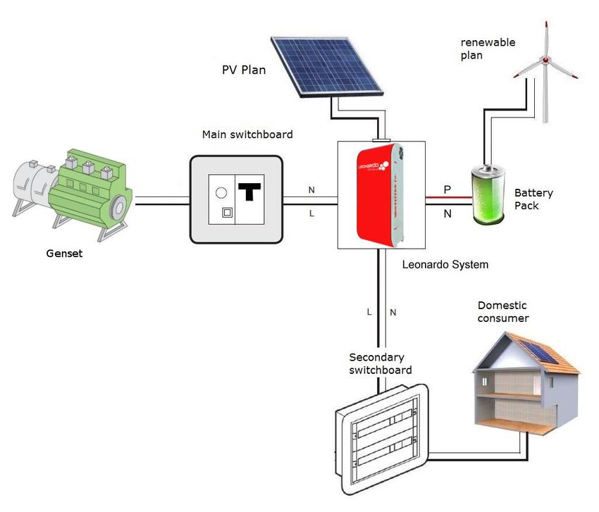
Leonardo Off-Grid 4kW/3000/48 GE
                                                    Manuale utente                                              IT
Istruzioni di sicurezza
            Pericolo di esplosione a causa di scintille
            Pericolo di folgorazione
            ATTENZIONE: non sollevare oggetti pesanti senza assistenza
Generale
•   Si consiglia di leggere attentamente questo manuale prima di installare e utilizzare il prodotto.
•   L’installazione e la manutenzione del prodotto deve essere svolta solo da personale qualificato.
•   Questo prodotto è progettato e testato in conformità agli standard internazionali. L'apparecchiatura deve essere
    utilizzata solo per l'applicazione per cui è stata progettata.
•   Il prodotto è utilizzato in combinazione con una fonte di energia permanente (batteria). Anche se l'apparecchiatura
    è spenta, può verificarsi una tensione elettrica pericolosa ai terminali di ingresso e / o uscita. Spegnere sempre
    l’eventuale alimentazione AC, le stringhe fotovoltaiche e scollegare la batteria prima di eseguire la manutenzione.
•   Il prodotto non contiene parti interne riparabili dall'utente. Non rimuovere il pannello frontale e non mettere in
    funzione il prodotto se non sono montati tutti i pannelli.
•   Non utilizzare mai il prodotto in luoghi in cui potrebbero verificarsi esplosioni di gas o polvere.
•   Fare riferimento alle specifiche fornite dal produttore della batteria per assicurarsi che sia idonea all'uso con
    questo prodotto. Le istruzioni di sicurezza del produttore della batteria devono essere sempre osservate.

Installazione e manutenzione
•   Questo prodotto è un dispositivo di sicurezza di I classe (fornito con un terminale di terra per motivi di sicurezza). I
    suoi terminali di ingresso e / o uscita AC devono essere dotati di messa a terra ininterrotta per motivi di sicurezza.
    Un ulteriore punto di messa a terra si trova all'esterno del prodotto. Se si può presumere che la protezione di
    messa a terra sia danneggiata, il prodotto dovrebbe essere messo fuori servizio impedendo che possa entrare in
    funzione accidentalmente; contattare personale di manutenzione qualificato.
•   Assicurarsi che i cavi di collegamento siano dotati di fusibili e interruttori automatici. Non sostituire mai un
    dispositivo di protezione con un componente di un tipo diverso.
•   Controllare prima di accendere il dispositivo se la sorgente di tensione disponibile è conforme alle impostazioni di
    configurazione del prodotto come descritto nel manuale.
•   Installare il prodotto in un ambiente che garantisce il range operativo di temperatura. Assicurarsi che non ci siano
    sostanze chimiche, parti in plastica, tende o altri tessuti che possono infiammarsi nelle immediate vicinanze
    dell'apparecchiatura. Non utilizzarlo mai in un ambiente umido.
•   Assicurarsi che ci sia sempre sufficiente spazio libero intorno al prodotto per la ventilazione e che le aperture di
    ventilazione non siano bloccate.
•   Proteggere i moduli solari dalla luce incidente durante l'installazione.
•   Non toccare mai le estremità del cavo non isolate. Utilizzare solo strumenti isolati.
•   I collegamenti devono sempre essere eseguiti nella sequenza descritta in questo manuale.
•   L'installatore del prodotto deve fornire un mezzo (es. fermacavi) per impedire che la trazione dei cavi si trasmetta
    alle connessioni rovinandole.
•   Oltre a questo manuale, le operazioni di installazione del sistema devono includere un manuale di manutenzione
    della batteria applicabile al tipo di batterie utilizzate.

Trasporto e stoccaggio
•   Durante lo stoccaggio o il trasporto del prodotto, assicurarsi che l'alimentazione di rete e i cavi della batteria siano
    scollegati.
•   Nessuna responsabilità può essere accettata per danni in transito se l'attrezzatura non viene trasportata nella sua
    confezione originale.
•   Conservare il prodotto in un ambiente asciutto; vedere il range operativo di temperatura per evitare di danneggiare
    il prodotto.
•   Fare riferimento al manuale del produttore della batteria per informazioni su trasporto, conservazione, carica,
    ricarica e smaltimento della batteria.

Le indicazioni riportate nel manuale non sostituiscono le norme di sicurezza vigenti nel paese di installazione e le regole
dettate dal comune buonsenso.

                                                            2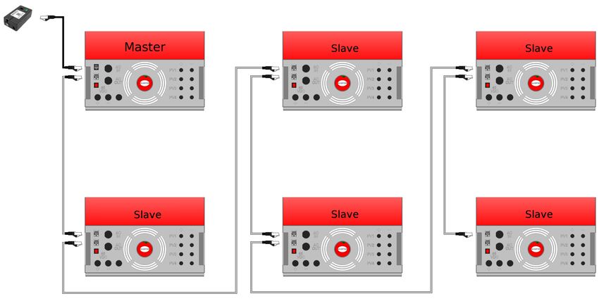
Leonardo Off-Grid 4kW/3000/48 GE
                                                     Manuale utente                                              IT
FUNZIONAMENTO DEL LEONARDO OFF-GRID 4kW/3000/48 GE

                               1.   Il Leonardo Off-Grid 4kW/3000/48 GE è progettato per ottenere un risparmio
                                    energetico diretto tramite l’utilizzo di energia fotovoltaica ed altre fonti rinnovabili;
                               2.   l'impianto fotovoltaico viene gestito tramite il regolatore di carica con n.4 ingressi
                                    MPPT indipendenti;
                               3.   l’inverter fornisce un risparmio di energia elettrica con produzione diretta dalle fonti
                                    rinnovabili o da energia immagazzinata in batteria;
                               4.   il Leonardo Off-Grid 4kW/3000/48 GE qualora l’energia disponibile da fonte
                                    rinnovabile sia insufficiente, garantisce una continuità di servizio grazie al gruppo
                                    elettrogeno collegato all’ingresso AC-IN;
                               5.   un contatto pulito per l'attivazione automatica permette l’accensione del gruppo
                                    elettrogeno che gestice la simultanea alimentazione di carichi e la ricarica della
                                    batteria;
                               6.   sulla linea delle utenze, AC-OUT, l’energia sarà erogata con la seguente priorità degli
                                    ingressi: autoconsumo diretto dai moduli FV ➔ autoconsumo da accumulo in
                                    batteria ➔ soccorso da gruppo elettrogeno;
                               7.   in caso di avaria del gruppo elettrogeno, tutta l’energia immagazzinata nelle batterie
                                    viene utilizzata per far fronte alla condizione di emergenza fino allo spegnimento
                                    dell’apparecchio che avviene ad una capacità residua del 10-20%.

     Fig.1 Pannello frontale

       POTENZA NOMINALE
       MAGGIORE DI
       3000 VA

                                                   Fig.2 Schema di principio

                                                              3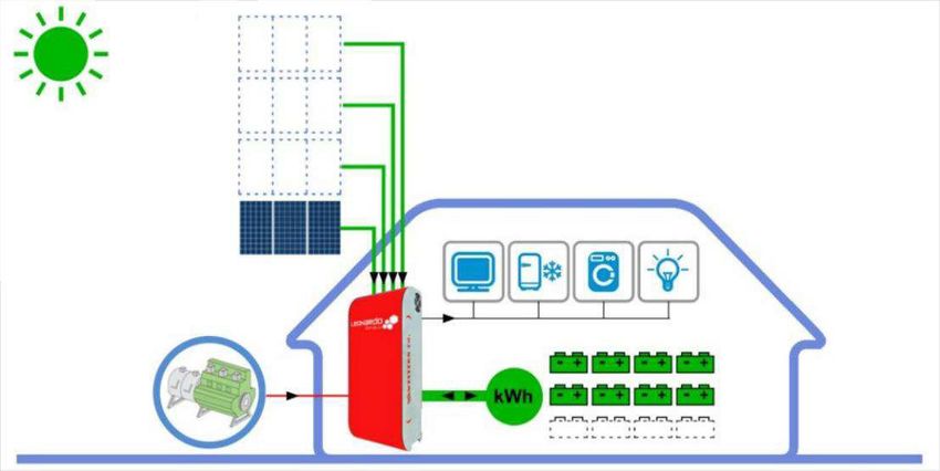
Leonardo Off-Grid 4kW/3000/48 GE
                                                    Manuale utente                                            IT
SCHEMA INTERNO

                                          LEONARDO
                                          DATA-LOGGER

   GRUPPO                                       5
   ELETTROGENO

        CONTATTO
        ACCENSIONE                     ACIN                             ACOUT1
        AUTOMATICA
                              1                            ACin ACout
                                                                                                          IMPIANTO
                            RELE'                                                                         DOMESTICO
                            APERTURA                                                                      PRILEGIATO
                            INGRESSO
                                                                              INVERTER
                                                          AC                  OFF-GRID
230Vac                        ENERGY                                           ISOLATO            230Vac
                              MANAGER
                                                                   DC
                                  2                                              4

                                                                                                           CAMPO FV
                                                                            DC
BATTERIA                              IBATT                            3             DC
                                                                           REGOLATORE
                                                                                                             6
    7
                            LEONARDO OFF-GRID                              MPPT 4-INPUT

                                                    Fig.3 Schema interno

Il Leonardo Off-Grid prevede uno schema interno come quello riportato nella figura superiore, tale configurazione
prevede che l'apparecchio abbia un collegamento ingresso AC-IN dal gruppo elettrogeno, se disponibile per l'abitazione,
con potenza nominale pari ad almeno 3000VA.
Il Leonardo Off-Grid possiede l'uscita AC-OUT dedicata alla connessione delle utenze domestiche, alimentate anche in
caso di avaria o assenza del gruppo elettrogeno.
L' Energy Manager, interno al Leonardo Off-Grid provvede al controllo ed alla gestione del sistema, inoltre fornisce una
visualizzazione rapida dello stato di funzionamento del sistema.
Il Leonardo Data-Logger, esterno all'apparecchio ed acquistabile separatamente, è un sistema di monitoraggio delle
informazioni sui flussi di potenza istantanei dell'apparecchio oltre che alla memorizzazione dei dati storici dell'energia
prodotta, accumulata, prelevata e complessivamente consumata.

                                                             4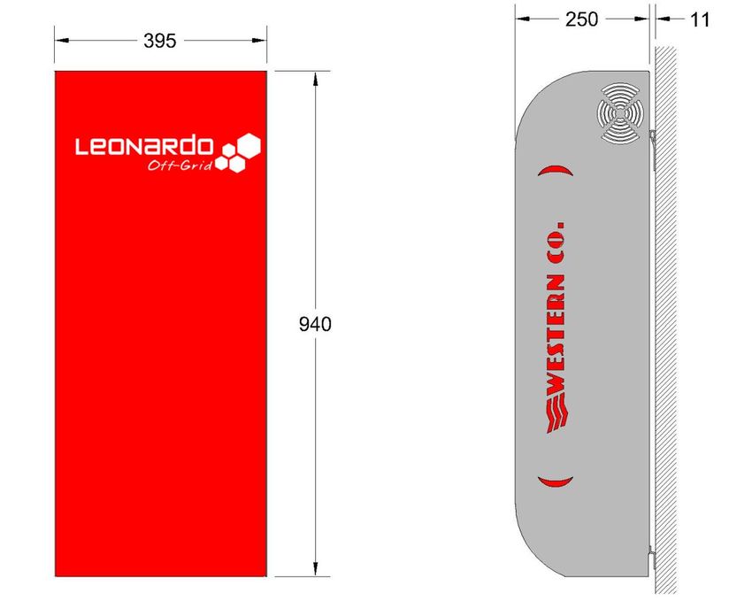
Leonardo Off-Grid 4kW/3000/48 GE
                                                Manuale utente                                   IT
SCHEMA DI COLLEGAMENTO                INVERTER DC/AC
                                      - Potenza continua 3000 VA
                                      - Potenza di sovraccarico 2500W
                                      - Ingresso AC
                                      - Batteria 48Vdc

DATA LOGGER OPZIONALE
- Energia prodotta
- Energia prelevata
- Indice di indipendenza energetica                                          CAMPO FV
                                                                             - 4 ingressi MPPT indipendenti
                                                                             - Potenza 4 kWp
                                                                             - Potenza singolo ingresso 1 kW

                                                                             BANCO BATTERIE
                                                                             - Tensione di sistema 48Vdc
                                                                             - Capacità consigliata
                                                                               impianto FV da 3kWp:
                                                                               200Ah - 9,6kWh
                                                                             - Capacità consigliata
                                                                               impianto FV da 4kWp:
                                                                               300Ah - 14,4kWh

   CONTATTO PER ACCENSIONE
   AUTOMATICA GRUPPO ELETTROGENO
   - contatto pulito COM-NC-NO
   - 4A @ 230VAC                              Fig.4 Schema di collegamento
   - 1A @ 60VDC
                                                            5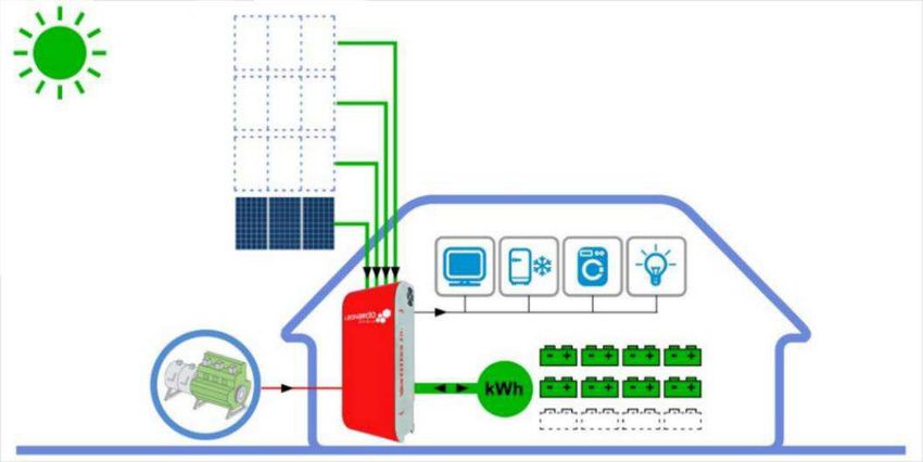
Leonardo Off-Grid 4kW/3000/48 GE
                                                       Manuale utente                                                  IT
PROTEZIONI ESTERNE
Protezioni lato Corrente Alternata
Il Leonardo Off-Grid 4kW/3000/48 GE è dotato di una linea di uscita in corrente alternata AC-OUT ed una linea di
ingresso in corrente alternata AC-IN.
Essendo l'apparecchio dotato di collegamento a terra del conduttore NEUTRO - sistema TT, la linea di uscita in corrente
alternata AC-OUT può essere protetta con un interruttore magnetotermico-differenziale di tipo AC, con corrente
nominale In=16A e corrente differenziale Id=0,03A (questo interruttore di solito è già presente nel quadro di
distribuzione dell'abitazione come protezione dai contatti indiretti, con corrente differenziale 30mA).
La linea di ingresso in corrente alternata AC-IN può essere protetta con un interruttore magnetotermico-differenziale di
tipo AC, con corrente nominale In=16A e corrente differenziale Id=0,3A, questo interruttore può essere inserito in un
quadro generale aggiuntivo o, se possibile, nel quadro di distribuzione esistente nell'abitazione.

Protezioni lato Corrente Continua
Il collegamento del banco batterie è effettuato tramite fusibile di protezione sul polo positivo, inoltre l'interruttore di
sezionamento del polo positivo provvede all'attivazione dell'inverter in completa sicurezza.

ATTENZIONE: gli accessori di montaggio del fusibile batteria sono pensati per batterie che hanno morsetti di fissaggio
con bulloni M8, nel caso di diverso diametro del bullone di fissaggio non sarà possibile utilizzare gli accessori a
corredo. In caso di utilizzo di un diverso tipo di fusibile esso deve essere dimensionato correttamente, altrimenti si
potrebbe compromettere il funzionamento del sistema.

        Dado plastico

        Occhiello d.10mm

        Fusibile 300A
                                                                                                         cavo INVERTER
        Dado M8 rondellato

        Occhiello d.8mm                                                                                cavo PARALLELO
                                                                                                             BATTERIA

        Grano M8 x 60mm

                                                   Fig.5 Fusibile di Protezione

INTERRUTTORE DI SEZIONAMENTO INVERTER
L'attivazione dell'interruttore di sezionamento del polo positivo di batteria realizza l'accensione dell'inverter in completa
sicurezza.

                    ATTENZIONE: nella sequenza di ACCENSIONE dell'apparecchio
                    l'interruttore di sezionamento batteria deve essere attivato ON
                    per PRIMO, rispetto ai collegamenti FV e corrente alternata
                    AC-IN e AC-OUT.
                     Nella     sequenza      di  SPEGNIMENTO       dell'apparecchio
                     l'interruttore di sezionamento batteria deve essere disattivato
                     OFF per ULTIMO, rispetto ai collegamenti FV e corrente
                     alternata AC-IN e AC-OUT.

                                                                                        Fig.6 Interruttore di sezionamento inverter

                                                                6
Leonardo Off-Grid 4kW/3000/48 GE
                                                      Manuale utente                                             IT
SEZIONE REGOLATORI DI CARICA FOTOVOLTAICA
Il Leonardo Off-Grid 4kW/3000/48 GE è dotato di regolatore di carica FV con 4 ingressi MPPT indipendenti: è un
regolatore di carica da moduli fotovoltaici per batterie elettrochimiche al piombo di tipo OPzV o OPzS.
Per il corretto riconoscimento della tensione di batteria eseguito all’accensione, di conseguenza imposta i parametri di
ricarica appropriati come descritto in Tab.1.

                         Tensione di batteria misurata all’avvio
                                40.0V < Vbatt < 64.0V                                 Batteria a 48V
                                             Tab. 1 Rilevamento Tensione di Sistema

Scelta del modulo fotovoltaico
Nella scelta della configurazione della stringa di moduli da impiegare nel sistema è necessario attenersi strettamente a
quanto indicato nella seguente tabella.
Grazie alla presenza del regolatore di carica con circuito di ricarica con MPPT, è possibile collegare i moduli a quattro
ingressi indipendenti garantendo così lo sfruttamento ottimale di tutta la potenza.

      Tensione nominale batteria            Caratteristiche moduli PV
      Batteria a 48V di tipo ermetico,      Moduli con 60 celle Si mono-cristallino / poli-cristallino per una
      tensione di carica in fase di         potenza tipica di 280 – 350 Wp.
      tensione costante (ABSORPTION)        Potenza per canale 1000 W (max 1150 Wp).
      Vch=57,6V alla temperatura di         Corrente di corto circuito massima: 13A per ogni ingresso.
      25°C                                  Tensione a circuito aperto massima: 200V per ogni ingresso.
                                              Tab.2 Scelta del Modulo Fotovoltaico

                                                             TAbs.

               Vch

               Vfloat
                                                     ABSORPTION
                                                                                      FLOAT
                                    BULK

                NOTTE                                                                                   NOTTE

                                                      Fig.7 Curva di carica

I livelli di tensione che il regolatore impone alla batteria Vch , Vfloat sono sempre riferiti alla temperatura nominale
di 25°C. Al variare della temperatura anche le tensioni imposte dal regolatore variano, secondo quanto consigliato
dai costruttori di batterie; diminuisce di -96mV/°C per ogni aumento di un grado di temperatura. I parametri di carica
riportati in Fig.7, con valore di fabbrica per batterie OPzV OPzS e tensione nominale di 48V, pari a Vch=57,6V e
Vfloat=55,2V.

                                                               7
Leonardo Off-Grid 4kW/3000/48 GE
                                                       Manuale utente                                               IT
SEGNALAZIONI ESTERNE
Sul lato laterale del Leonardo Off-Grid 4kW/3000/48 GE sono presenti le segnalazioni di funzionamento
dell’inverter: Inverter Mode e Bypass Mode, lo stato di carica della batteria, la potenza assorbita dal carico, lo stato
del carica da fotovoltaico e la presenza della rete AC dal gruppo elettrogeno.

                                                Fig.8 Segnalazione Inverter Mode

Nel caso in Fig.8 è possibile notare lo stato di funzionamento dell’inverter in modalità Inverter Mode: il carico viene
alimentato dalle fonti rinnovabili, la batteria presenta uno stato di carica con almeno il 75% di carica residua, il carico
assorbe una potenza compresa tra 200W e 1000W, il carica batteria da fotovoltaico è attivo, il gruppo elettrogeno
collegato all'ingresso AC-IN è spento.
Nel caso di mancanza di fonte rinnovabile la batteria raggiunge lo stato di carica residua del 40%, quindi si passa alla
modalità di funzionamento Bypass Mode:

                                                 Fig.9 Segnalazione Bypass Mode

Nel caso in Fig.9 infatti è possibile notare lo stato di funzionamento dell’inverter in modalità Bypass Mode: il carico
viene alimentato dal gruppo elettrogeno, la batteria presenta uno stato di carica con almeno il 25% di carica residua,
il carico assorbe una potenza compresa tra 1000W e 2200W, il carica batteria da fotovoltaico è attivo, la tensione di
uscita AC dal gruppo elettrogeno è presente all'ingresso AC-IN e viene utilizzata per alimentazione del carico e carica
del banco batterie.

Protezione da sovraccarico
Quando si verifica un sovraccarico di potenza sul carico d’uscita (se la potenza supera il limite di 3000 VA ) l'inverter
si spegne per protezione da sovraccarico, per ripristinare il normale funzionamento, agire sull'apposito tasto di
RESET, dopo aver rimosso la causa del sovraccarico.

            ATTENZIONE: il gruppo elettrogeno viene utilizzato per alimentazione delle utenze domestiche e per la
            carica delle batterie al fine di ottimizzare il consumo di carburante. E' assolutamente necessario
            utilizzare un gruppo elettrogeno di potenza maggiore o uguale a 3000VA.

                                                               8
Leonardo Off-Grid 4kW/3000/48 GE
Manuale utente IT
LOGICA DI FUNZIONAMENTO
Home Consumption
PV Production
Genset Power
Battery Power
Fig.10 Logica di funzionamento
Tabella Stato di carica e potenza di uscita
Stato di carica SOC livello 4, l'energia
effettivamente stoccata in batteria si Potenza di uscita LOAD livello 4, la
trova in un intervallo compreso tra potenza elettrica delle utenze in uscita è
85% - 100% della propria capacità superiore al livello di 4000W.
nominale (Tensione maggiore di 54,4V).
Stato di carica SOC livello 3, l'energia
Potenza di uscita LOAD livello 3, la
effettivamente stoccata in batteria si
potenza elettrica delle utenze in uscita è
trova in un intervallo compreso tra
compresa in un intervallo di
60% - 85% della propria capacità nominale
2200W - 4000W.
(tensione maggiore di 48V).
Stato di carica SOC livello 2, l'energia
Potenza di uscita LOAD livello 2, la
effettivamente stoccata in batteria si
potenza elettrica delle utenze in uscita è
trova in un intervallo compreso tra
compresa in un intervallo di
40% - 60% della propria capacità nominale
1000W - 2200W.
(tensione maggiore di 46V).
Stato di carica SOC livello 1, l'energia
Potenza di uscita LOAD livello 1, la
effettivamente stoccata in batteria si
potenza elettrica delle utenze in uscita è
trova in un intervallo compreso tra
compresa in un intervallo di
30% - 40% della propria capacità nominale
200W - 1000W.
(tensione maggiore di 42V).
Tab.3 Stato di Carica e Potenza di Uscita
9Leonardo Off-Grid 4kW/3000/48 GE
Manuale utente IT
Tabella segnalazione LED STATUS
LED STATUS
Led VERDE: normale stato di funzionamento attivo ON.
LED STATUS
Led ROSSO n.1 lampeggio ogni 10 Secondi: stato di allarme SOVRA-TEMPERATURA.
LED STATUS
Led ROSSO n.2 lampeggi ogni 10 Secondi: stato di allarme LOW-BATTERY.
LED STATUS
Led ROSSO n.3 lampeggi ogni 10 Secondi: stato di allarme OVER-LOAD.
Tab.4 Segnalazione LED STATUS
ATTENZIONE: in caso di BLOCCO dell'inverter, nessuna tensione di alimentazione sull'uscita AC-OUT,
causa una delle tre condizioni di anomalia indicate in Tab.4, è necessario un RIAVVIO dell'apparecchio,
attraverso la pressione del tasto di RESET presente alla base dell'apparecchio (Fig. 12).
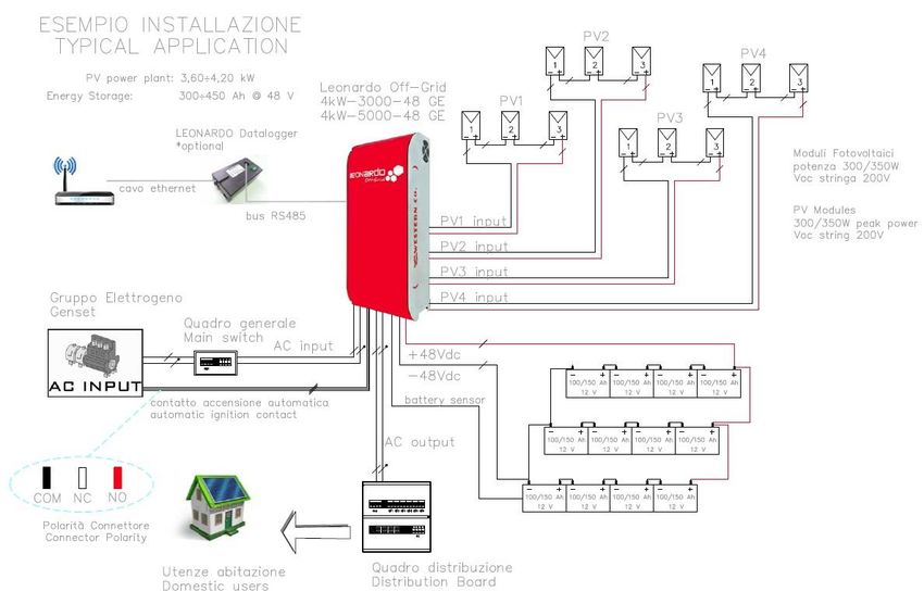
INSTALLAZIONE E CABLAGGIO
a) Installare il Leonardo Off-Grid 4kW/3000/48 GE in un luogo asciutto ed adeguatamente arieggiato, fissato su di
una superficie non infiammabile e posizionato in modo da lasciare uno spazio privo di ostacoli di almeno 10cm
nell’intorno del dispositivo che ne permette il raffreddamento per convezione forzata dell’aria.
b) Fissare a muro la staffa di supporto (fornita in dotazione) tramite i tasselli e le viti fornite in dotazione;
successivamente agganciare l’inverter tramite la piastra ad uncino posta nella parte superiore dell’apparecchio.
Infine fissare l’inverter alla parete utilizzando i fori predisposti nella parte inferiore dell’apparecchio. Il tutto come
indicato in Fig.11.
PIASTRA AD
UNCINO parte
superiore dell’inverter
STAFFA DI
SUPPORTO
PIASTRA parte
inferiore dell’inverter
Fig.11 Montaggio a parete
c) Collegare nell’ordine:
1. cavo batteria positivo (vedi collegamento nella sezione Protezioni Lato Corrente Continua);
2. cavo batteria negativo;
3. attivare l'interruttore di sezionamento batteria - posizione ON;
4. collegare i moduli fotovoltaici PV1-PV2-PV3-PV4 (verificando la polarità di ciascuna coppia di cavi che
dovrà essere collegata in ingresso all’inverter);
10Leonardo Off-Grid 4kW/3000/48 GE
Manuale utente IT
5. collegare ingresso AC-IN su connessione AC Input tramite connettori AC plug and play tipo RST (se presente
il gruppo elettrogeno);
6. collegare uscita AC-OUT su connessione AC Output tramite connettori AC plug and play tipo RST
7. posizionare infine l’apposito cavo al sensore di temperatura delle batterie in prossimità della stessa, al fine
di un corretto rilevamento.
L’apparecchio viene dotato di cavo per collegamento batteria di lunghezza 1,5m quindi è assolutamente raccomandato
installare il banco batteria ad una distanza tale da mantenere il cavo originale per il collegamento.
Aumentare la distanza con il banco batterie comporta un aumento della caduta di tensione sul cavo in fase di
funzionamento quindi una errata lettura della tensione di batteria.
La sezione dei cavi batteria è di 25 mm2.
Utilizzare il cavo in dotazione per effettuare il collegamento ai morsetti principali di batteria e nel caso di un banco
batteria costituito da più elementi in serie o in parallelo utilizzare un cavo di sezione minima 50 mm 2 per il cablaggio di
ciascun elemento in serie o in parallelo.
In caso di installazione di sistemi trifase o più macchine in parallelo o di banco batterie costituito da molti elementi è
assolutamente consigliata l’installazione di una barra di rame per il cablaggio delle batterie.
Si raccomanda l’installazione dell’apparecchio su parete solida in posizione verticale, al fine di assicurare un adeguato
ricircolo di aria, dovuta alla ventilazione forzata dell’apparecchio. Per tale motivo è inoltre da evitare l’installazione in
luoghi ricchi di polvere e sporco.
11Leonardo Off-Grid 4kW/3000/48 GE
Manuale utente IT
CABLAGGIO - CONTATTO DI ACCENSIONE AUTOMATICA GRUPPO ELETTROGENO
I prodotti della serie Leonardo Off-Grid GE, modelli 1kW/1500/24, 4kW/3000/48, 4kW/5000/48 e 8kW/8000/48, hanno
la gestione di un contatto ausiliario pulito, per il collegamento di un gruppo elettrogeno di emergenza con dispositivo di
accensione automatica, collegato all'ingresso AC INPUT.
AC OUTPUT AC INPUT - GENERATORE PV INPUT + PV INPUT -
Cablaggio tramite connettori plug Cablaggio tramite connettori plug Numero 4 ingressi positivi Numero 4 ingressi negativi
and play a 3 poli - 6mm^2 and play a 3 poli tipo in figura Cablaggio plug and play Cablaggio plug and play
4-6mm^2 4-6mm^2
(in fig. controparte maschio) (in fig. controparte femmina)
Uscita PLUG NERO
DATALOGGER
Uscita PLUG
BIANCO SYNC
TASTO RESET
INVERTER
Uscita Cavi DC
Batteria
Lunghezza cavo 1,5m
Sezione 25 mm^2
CONTATTO GENERATORE -
Numero 3 Poli del contatto
NC - COM - NO
(in fig. connettore)
Ingresso sensore di
temperatura
Lunghezza cavo 1,5 m
POLARITA’ DELLA CONNESSIONE
COM-NERO NC-BIANCO NO-ROSSO
Fig.12 Cablaggio
L’apparecchio gestisce il contatto pulito ausiliario con la seguente programmazione:
1. contatto attivo per una tensione inferiore ai 45V (o 22,5V per 1kW/1500/24), entro 10 secondi;
2. il dispositivo Leonardo Off-Grid accetta all'ingresso AC INPUT la connessione di uscita 230Vac dal gruppo
elettrogeno con corrente potenza di ricarica massima pari a: 0,75kW e corrente di carica 30A@24V per il
modello 1kW/1500/24 GE - 1,5kWp e corrente di carica 30A@48V per il modello 4kW/3000/48 GE -
2,5kWp e corrente massima 50A@48V per il modello 4kW/5000/48 GE - 4kW e corrente massima
80A@48V per il modello 8kW/8000/48 GE;
3. il dispositivo Leonardo Off-Grid contemporaneamente carica la batteria ed alimenta le utenze, al fine di
ridurre al minimo i tempi di accensione del gruppo elettrogeno;
4. quando la fase di carica BULK (corrente costante) della batteria è stata completata, dopo 10 minuti, il
Leonardo Off-Grid torna ad alimentare le utenze;
5. entro 2 minuti il contatto viene disattivato per lo spegnimento del gruppo elettrogeno.
12Leonardo Off-Grid 4kW/3000/48 GE-SL
Manuale utente IT
AVVIAMENTO E COLLAUDO DELL’IMPIANTO
Appena realizzati i collegamenti come in Fig.12 è necessario procedere avviamento e collaudo del sistema:
1) verificare l’accensione del Leonardo Off-Grid 4kW/3000/48 GE al termine del collegamento dei cavi sui morsetti
della batteria ed attivazione dell'interruttore di sezionamento batteria;
2) verificare la corretta carica di batteria, in caso contrario verificare la corretta installazione del banco batterie;
3) verificare l’attivazione della linea di uscita AC-OUT, se presente un carico l’inverter eroga potenza e lo stato è
disponibile dalle indicazioni luminose del carico LOAD;
4) in base alle condizioni di carica della batteria, della presenza del gruppo elettrogeno di ingresso, si può osservare
il corretto funzionamento della logica di funzionamento dell’inverter, come da Fig. 10.
EVENTUALI PROBLEMATICHE E SOLUZIONI
• Led AC IN spento → Verificare la tensione in uscita dal gruppo elettrogeno e il cablaggio del connettore AC-IN.
• Assenza tensione in uscita AC-OUT → Verificare il cablaggio del connettore AC-OUT. Verificare se l’Energy
Manager presenta entrambi i led BYPASS e INVERTER spenti.
• Entrambi i Led “Bypass” e “Inverter” spenti → Provvedere a resettare l’inverter eseguendo la procedura come
da manuale. Ad inverter spento girare solo il sezionatore DC delle batterie e verificare l’accensione del Led
BATTERY e del Led INVERTER. Verificare l’integrità di eventuali fusibili DC di protezione. Se il problema permane
si consiglia di contattare l’assistenza tecnica Western CO.
• Led PV CHARGE sempre spento → Verificare il cablaggio delle stringhe fotovoltaiche.
• Led STATUS spento. Effettuare reset inverter come da manuale.
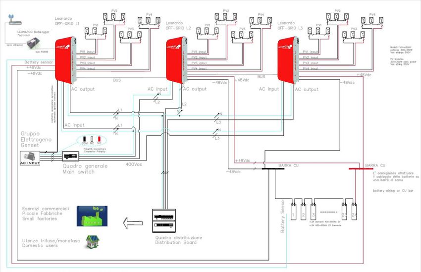
APPLICAZIONI TRIFASE O PARALLELO CON VERSIONE SLAVE SL
Leonardo Off-Grid 4kW/3000/48 GE, versione Master per applicazioni con ingresso da rete, ha la possibilità di
installazione in impianti di tipo TRIFASE o PARALLELO attraverso l'utilizzo del codice Leonardo Off-Grid 4kW/3000/48
SL, versione SLAVE.
Ogni installazione prevede n.1 inverter di tipo Master e N inverter di tipo Slave a seconda della configurazione.
Ad esempio:
Impianto Trifase tot. 9kW:
Fase L1 n.1 Master - Fase L2 n.1 Slave - Fase L3 n.1 Slave
INVERTER MASTER L1 INVERTER SLAVE L2 INVERTER SLAVE L3
A - Plug Datalogger A - Plug Sincronismo A - Plug Sincronismo
B - Plug Sincronismo B - Plug Sincronismo B - non connesso
CAVO
CAVO SYNC CAVO SYNC
DATALOGGER
Cavo Patch 8 poli Cavo Patch 8 poli
Cavo Patch
8 poli
Fig.13 Schema di collegamento BUS di controllo Sync dell’impianto trifase 9 kW
13Leonardo Off-Grid 4kW/3000/48 SL
Manuale utente IT
Schema Unifilare dell'impianto trifase 9kW.
Fig.14 Schema Unifilare dell'impianto trifase 9Kw
14Leonardo Off-Grid 4kW/3000/48 SL
Manuale utente IT
Impianto Trifase tot. 18kW:
Fase L1 n.1 Master + n.1 Slave - Fase L2 n.2 Slave - Fase L3 n.2 Slave
INVERTER MASTER L1 INVERTER SLAVE L2 INVERTER SLAVE L3
A - Plug Datalogger A - Plug Sincronismo A - Plug Sincronismo
B - Plug Sincronismo B - Plug Sincronismo B - Plug Sincronismo
CAVO
DATALOGGER
Cavo Patch
8 poli
CAVO SYNC CAVO SYNC CAVO SYNC
Cavo Patch 8 poli Cavo Patch 8 poli Cavo Patch 8 poli
INVERTER SLAVE L1 INVERTER SLAVE L2 INVERTER SLAVE L3
A - Plug Sincronismo A - Plug Sincronismo A - Plug Sincronismo
B - Plug Sincronismo B - Plug Sincronismo B – non connesso
CAVO SYNC CAVO SYNC
Cavo Patch 8 poli Cavo Patch 8 poli
Fig.15 Schema di collegamento BUS di controllo Sync dell’impianto trifase 18 kW
Impianto Parallelo tot. 6kW:
Fase L1 n.1 Master + n.1 Slave
INVERTER MASTER L1
A - Plug Datalogger
B - Plug Sincronismo
CAVO
DATALOGGER
Cavo Patch 8 poli
CAVO SYNC
Cavo Patch 8 poli
INVERTER SLAVE L1
A - Plug Sincronismo
B - non connesso
Fig.16 Schema di collegamento BUS di controllo Sync dell’impianto parallelo 6 kW
15Leonardo Off-Grid 4kW/3000/48
Manuale utente IT
CARATTERISTICHE MECCANICHE E PESO
Leonardo Off-Grid 4kW/3000/48 GE = 25 kg
Fig.17 Caratteristiche meccaniche
16Leonardo Off-Grid 4kW/3000/48
Manuale utente IT
CARATTERISTICHE ELETTRICHE
Leonardo Off-Grid Leonardo Off-Grid Leonardo Off-Grid Leonardo Off-Grid
1kW / 1500 / 24 GE 4kW / 3000 / 48 GE 4kW / 5000 / 48 GE 8kW / 8000 / 48 GE
Min Tip Max Min Tip Max Min Tip Max Min Tip Max
Potenza di uscita Pout - 1.500VA 3.000W - 3.000VA 6.000W - 5.000VA 10.000W - 8.000VA 16.000W
Tensione di batteria Vbatt 20,0V 24V 33V 40,0V 48V 66V 40,0V 48V 66V 40,0V 48V 66V
Tensione di uscita Vac - 230V - - 230V - - 230V - - 230V -
50Hz 50Hz 50Hz 50Hz
Frequenza di uscita Fac - - - - - - - -
±0,1% ±0,1% ±0,1% ±0,1%
Tempo di trasferimento
Tsw - 10mS - - 10mS - - 10mS - - 10mS -
Inverter Bypass
Soglia di sovraccarico Poc - 85% - - 85% - - 85% - - 85% -
INVERTER
Efficienza Eff - 94% - - 95% - - 95% - - 95% -
Assorbimento in bypass Pbp -Leonardo Off-Grid 4kW/3000/48
Manuale utente IT
GARANZIA DI LEGGE
Western CO. srl garantisce la buona qualità e la buona costruzione dei Prodotti obbligandosi, durante il periodo di
garanzia di 5 (cinque) anni, a riparare o sostituire a sua sola discrezione, gratuitamente, quelle parti che, per cattiva
qualità del materiale o per difetto di lavorazione si dimostrassero difettose.
Il prodotto difettoso dovrà essere rispedito alla Western CO. srl o a società delegata dalla Western CO. srl a fare
assistenza sul prodotto, a spese del cliente, assieme ad una copia della fattura di vendita, sia per la riparazione che la
sostituzione garantita. I costi di re-installazione del materiale saranno a carico del cliente.
La Western CO. srl sosterrà le spese di re spedizione del prodotto riparato o sostituito.
La garanzia non copre i Prodotti che, in base a nostra discrezione, risultino difettosi a causa di naturale logoramento,
che presentino guasti causati da imperizia o negligenza del cliente, da imperfetta installazione, da manomissioni o
interventi diversi dalle istruzioni da noi fornite.
La garanzia decade altresì in caso di danni derivanti da:
-trasporto e/o cattiva conservazione del prodotto.
-causa di forza maggiore o eventi catastrofici (gelo per temperature inferiori a -20°C, incendio, inondazioni, fulmini, atti
vandalici, ecc …).
Tutte le sopraccitate garanzie sono il solo ed esclusivo accordo che soprassiede ogni altra proposta o accordo verbale o
scritto e ogni altra comunicazione fatta tra il produttore e l’acquirente in rispetto a quanto sopra.
Per qualsiasi controversia il Foro competente è Ascoli Piceno. Per ulteriori informazioni, consultare il documento
“Garanzia Leonardo” al seguente link: https://www.western.it/garanzia/
SMALTIMENTO DEI RIFIUTI
La Western CO. in qualità di produttore del dispositivo elettrico descritto nel presente
manuale, ed in conformità al D.L 25/07/05 n 151, informa l’acquirente che questo prodotto,
una volta dismesso, deve essere consegnato ad un centro di raccolta autorizzato oppure, in
caso di acquisto di apparecchiatura equivalente può essere riconsegnato a titolo gratuito al
distributore della apparecchiatura nuova.
Le sanzioni per chi abusivamente si libera di un rifiuto elettronico saranno applicate dalle
singole amministrazioni comunali.
WESTERN CO. Srl
Via Pasubio, 1
63074 San Benedetto del Tronto (AP)
tel: (+39) 0735 751248 fax: (+39) 0735 751254
e-mail: info@western.it
web: www.western.it
18Leonardo Off-Grid 4kW/3000/48 GE
User Manual EN
LEONARDO OFF-GRID 4kW/3000/48 GE
• Photovoltaic production and storage
system
• MPPT recharge through charge
controllers with 4 independent inputs
• Max PV power 4kWp @ 48V
• AC input for Genset bypass
• Pure sine wave DC / AC Inverter
• Continuous Power 3000 VA
• Output voltage: 230V 50Hz
• Inverter efficiency 95%
• PV charge controller efficiency 97.2%
• Contact for automatic ignition of the
Genset
• Battery cut-off switch
Leonardo Off-Grid 4kW/3000/48 GE has been conceived and specially
developed for the production and storage of domestic energy; combined • Battery voltage 48Vdc
with photovoltaic modules and storage batteries, it provides power to the • Lead Batteries for cyclic use OPzS,
house until it is fully self-sustaining.
Leonardo Off-Grid 4kW/3000/48 GE makes it easy and immediate the use OPzV
of energy produced by photovoltaic modules, for the supply of domestic • Low battery protection
consumptions, with the possibility of using a genset (back-up) in case of
• Battery temperature sensor
reduced renewable energy.
The system provides four independent MPPT inputs through a dedicated • Short circuit and AC overload
charge controller: this technology implements a search circuit of maximum protection
power depending on the voltage and current of the PV module, always
• Over-Temperature protection
maximizing the energy delivered.
By connecting a genset to the input AC input, the system ensures continuity • IP20 housing
of operation of the users without perceptible discontinuity in case of low • Easy wiring
battery due to the reduced availability of renewable energy. In fact, the
genset simultaneously manages the power supply of the loads and the • Optional Battery Box
charge of the battery bank.
1
REV 6.3 28-06-2019Leonardo Off-Grid 4kW/3000/48 GE
User Manual EN
Safety instructions
Danger of explosion from sparking
Danger of electric shock
WARNING: do not lift heavy objects unassisted.
In general
• Read the installation instructions before commencing installation activities.
• The product installation and maintenance must be performed only by qualified personnel.
• This product is designed and tested in accordance with international standards. The equipment should be used for
the designed application only.
• The product is used in combination with a permanent energy source (battery). Even if the equipment is switched
off, a dangerous electrical voltage can occur at the input and/or output terminals. Always switch the AC power off,
Photovoltaic strings and disconnect the battery before performing maintenance.
• The product contains no internal user-serviceable parts. Do not remove the frontal panel and do not put the
product into operation unless all panels are fitted.
• Never use the product at sites where gas or dust explosions could occur.
• Refer to the specifications provided by the manufacturer of the battery to ensure that it is suitable for use with this
product. The battery manufacturer’s safety instructions should always be observed.
Installation and maintenance
• This product is safety class I device (supplied with a ground terminal for safety purposes). Its AC input and/or
output terminals must be provided with uninterruptible grounding for safety purposes. An additional grounding
point is located in the outside of the product. If it can be assumed that the grounding protection is damage, the
product should be taken out of operation and prevented from accidentally being put into operation again; contact
qualified maintenance personnel.
• Ensure that the connection cables are provided with fuses and circuit breakers. Never replace a protective device
by a component of a different type.
• Check before switching the device on whether the available voltage source conforms to the configuration settings
of the product as described in the manual.
• Install the product in an environment that guarantees the operating temperature range. Ensure that there are no
chemicals, plastic parts, curtains or other fabrics that can ignite in the immediate vicinity.
• Ensure that there is always sufficient free space around the product for ventilation, and that ventilations openings
are not blocked.
• Protect the solar modules from incident light during installation.
• Use only insulated tools. Never touch uninsulated cable ends.
• Connections must always be made in the sequence described in this manual.
• The installer of the product must provide a means for cable stain relief to prevent the transmission of stress to the
connections.
• In addition to this manual, the system operations or service manual must include a battery maintenance manual
applicable to the type of batteries used.
Transport and storage
• On storage or transport of the product, ensure that the mains supply and battery leads are disconnected.
• No liability can be accepted for damage in transit if the equipment is not transported in its original packaging.
• Store that product in a dry environment; see the operating temperature range to avoid damaging the product.
• Refer to the battery manufacturer’s manual for information on transport, storage, charging, recharging and
disposal of the battery.
Recommendations given in this manual do not replace the safety regulations of the country of installation and the rules
dictated by common sense.
2Leonardo Off-Grid 4kW/3000/48 GE
User Manual EN
LEONARDO OFF-GRID 4kW / 3000/48 GE WORKING PRINCIPLES
1. Leonardo Off-Grid 4kW/3000/48 GE is designed to achieve direct energy savings
through the use of photovoltaic energy and other renewable sources;
2. the photovoltaic system is managed by the charge controller with 4 independent
MPPT inputs;
3. the inverter provides electricity savings with direct production from renewable
sources or from energy stored in the battery;
4. the Leonardo Off-Grid 4kW/3000/48 GE if the energy available from renewable
sources is insufficient, it guarantees a continuity of service thanks to the genset
connected to the AC-IN input;
5. a clean contact for automatic activation allows the switching on of the genset that
manages the simultaneous feeding of loads and the recharging of the battery;
6. on the user line, AC-OUT, the energy will be delivered with the following priority of
the inputs: self-consumption directed by PV modules ➔ self-consumption by
accumulation in the battery ➔ emergency from a genset;
7. in case of failure of the genset, all the energy stored in the batteries is used to cope
with the emergency condition until the device is switched off, which takes place at a
residual capacity of 10-20%.
Pic.1 Front panel
NOMINAL POWER
GREATER THAN
3000 VA
Pic.2 Principle diagram
3Leonardo Off-Grid 4kW/3000/48 GE
User Manual EN
INTERNAL DIAGRAM
LEONARDO
DATA-LOGGER
GRUPPO 5
ELETTROGENO
CONTATTO
ACCENSIONE ACIN ACOUT1
AUTOMATICA
1 ACin ACout
IMPIANTO
RELE' DOMESTICO
APERTURA PRILEGIATO
INGRESSO
INVERTER
AC OFF-GRID
230Vac ENERGY ISOLATO 230Vac
MANAGER
DC
2 4
CAMPO FV
DC
BATTERIA IBATT 3 DC
REGOLATORE
6
7
LEONARDO OFF-GRID MPPT 4-INPUT
Pic.3 Internal diagram
The Leonardo Off-Grid provides an internal diagram such as that shown in the upper picture, this configuration provides
that the device has an AC-IN input connection from the genset, if available for housing, with a nominal power of at least
3000VA.
The Leonardo Off-Grid has the AC-OUT output dedicated to the connection of domestic consumptions, also powered in
case of failure or absence of the genset.
The Energy Manager, inside the Leonardo Off-Grid, provides for the control and management of the system and also
provides a quick view of the operating status of the system.
Leonardo Data-Logger, optional from the device and sold separately, provides information about instantaneous power
flow of the device as well as the archiving of the historical data of the energy produced, stored, picked and consumed as
a whole.
4Leonardo Off-Grid 4kW/3000/48 GE
User manual EN
CONNECTION DIAGRAM
DC / AC INVERTER
- Continuous Power 3000 VA
- 2500W overload power
- AC input
- 48Vdc Battery
OPTIONAL DATA LOGGER
- Produced energy
- Drawn energy
- Index of Energy independence PV FIELD
- 4 independent MPPT inputs
- Power 4 kWp
- Single input power 1 kW
BATTERY BENCH
- 48Vdc system voltage
- Recommended capacity
3kWp PV system:
CONTACT FOR AUTOMATIC 200Ah - 9.6kWh
IGNITION POWER GENSET - Recommended capacity
- clean contact COM-NC-NO 4kWp PV system:
- 4A @ 230VAC Pic.4 Connection diagram 300Ah - 14.4kWh
- 1A @ 60VDC
5Leonardo Off-Grid 4kW/3000/48 GE
User Manual EN
EXTERNAL PROTECTION
Protections for Alternating Current side
Leonardo Off-Grid 4kW/3000/48 GE is equipped with an AC-OUT alternating current output line and an AC-IN
alternating current input line.
Since the device has a conductor connected to the NEUTRAL - TT system, the AC output line AC-OUT can be protected
with a thermal-magnetic circuit breaker AC type, with nominal current In = 16A and differential current Id = 0.03 (usually
this switch is already in the house switchboard as protection against indirect contact, with 30mA of differential current).
The input line into alternating current AC-IN can be protected with a thermal-magnetic circuit breaker AC type, with
nominal current In = 16A and differential current Id = 0.3A, this switch can be put in an additional general switchboard
or, if possible, in the existing switchboard of the house.
Protections Direct Current side
The battery bank is connected through a protective fuse to the positive pole, and the positive pole disconnection switch
ensures that the inverter is activated in complete safety.
ATTENTION: the battery fuse mounting accessories are designed for batteries that have fixing clamps with M8 bolts,
in the case of different diameter of the fixing bolt it will not be possible to use the accessories supplied. If a different
type of fuse is used, it must be sized correctly, otherwise the system may be impaired.
Plastic nut
Eyelet d.10mm
300A fuse
INVERTER cable
M8 round nut
Eyelet d. 8mm PARALLEL
BATTERY cable
Grain M8 x 60mm
Pic.5 Protection Fuse
INVERTER CIRCUIT BREAKER
The activation of the positive pole of the cutting switch provides the power of the inverter in complete safety.
ATTENTION: in the device ON sequence the circuit breaker
must be activated ON for FIRST, with respect to the PV
connections and AC-IN and AC-OUT alternating current.
In the device OFF sequence of the device, the circuit breaker
must be deactivated on OFF for LAST, compared to the PV
connections and AC-IN and AC-OUT alternating current.
Pic.6 Inverter circuit breaker
6Leonardo Off-Grid 4kW/3000/48 GE
User Manual EN
PHOTOVOLTAIC CHARGE CONTROLLER SECTION
Leonardo Off-Grid 4kW / 3000/48 GE is equipped with PV charge controller with 4 independent MPPT inputs: is a
charge controller for photovoltaic modules for lead electrochemical batteries of the OPzV or OPzS type.
For the correct recognition of the battery voltage performed at power up, it accordingly sets the appropriate charging
parameters as described in Tab.1.
Battery voltage measured at start-up
40.0VLeonardo Off-Grid 4kW/3000/48 GE
User Manual EN
EXTERNAL SIGNALS
On the lateral side of Leonardo Off-Grid 4kW/3000/48 GE there are the working reports of the inverter: Inverter
Mode - By-pass Mode, the status of the battery charge, the power absorption of the load, the status of the
photovoltaic charge and the presence of the AC grid in input.
Pic.8 Inverter Mode signal
In the case in Pic.8 it is possible to note the operating status of the inverter in mode Inverter Mode: the load is
powered by renewable sources, the battery has a state of charge with at least 75% of residual charge, the load
absorbs a power between 200W and 1000W, the photovoltaic battery charger is active, the genset connected to the
AC-IN input is off.
If there is no renewable source, the battery reaches the remaining charge level of 40%, then it switches to the
operating mode Bypass Mode:
Pic.9 Bypass Mode signaling
In the case in Pic.9 in fact it is possible to note the operating status of the inverter in mode Bypass Mode: the load is
powered by the genset, the battery has a state of charge with at least 25% of residual charge, the load absorbs a
power between 1000W and 2200W, the photovoltaic battery charger is active, the AC output voltage from the
genset is present at the AC-IN input and is used for power supply and battery bank charge.
Overload protection
When there is a power overload on the output load (if the power exceeds the limit of 3000 VA) the inverter switches
off due to overload protection, to restore normal operation, act on the appropriate RESET key, after removing the
cause of the overload.
ATTENTION: the genset is used to power domestic consumptions and to charge the batteries in order to
optimize fuel consumption. It is absolutely necessary to use a genset with power greater than or equal
to 3000VA.
8Leonardo Off-Grid 4kW/3000/48 GE
User Manual EN
OPERATING LOGIC
Home Consumption
PV Production
Genset Power
Battery Power
Pic.10 Operating logic
Charge status and output power table
SOC charge status level 4, the actually
stored energy in the battery is in an Output power LOAD level 4, the output
interval of between 85% - 100% of its electric power of the consumptions is
nominal capacity. (Voltage higher than higher than the level of 4000W.
54,4V).
SOC charge status level 3, the actually
stored energy in the battery is in an Output Power LOAD level 3, the output
interval of between 60% - 85% of its electric power of the consumptions is in a
nominal capacity. (Voltage higher than range of 2200W - 4000W.
48V).
SOC charge status level 2, the actually
Output Power LOAD level 2, the output
stored energy in the battery is in an
electric power of the consumptions is in a
interval of between 40% - 60% of its rated
range of 1000W - 2200W.
capacity. (Voltage higher than 46V).
SOC charge status level 1, the actually
stored energy in the battery is in an Output power LOAD level 1, the electric
interval of between 30% - 40% of its power of the consumptions is included in
nominal capacity. (Voltage higher than a range of 200W - 1000W.
42V).
Tab.3 Charge status and Output Power
9Leonardo Off-Grid 4kW/3000/48 GE
User Manual EN
LED STATUS warning table
LED STATUS
GREEN LED: normal working status activated ON.
LED STATUS
no.1 flash of RED Led every 10 seconds: OVER-TEMPERATURE alarm status.
LED STATUS
No.2 RED LED flashes every 10 seconds: LOW-BATTERY alarm status.
LED STATUS
No.3 RED led flashes every 10 seconds: OVER-LOAD alarm status.
Tab.4 STATUS LED signalling
WARNING: in case of BLOCKED inverter, there is no supply voltage at the output AC-OUT, because
occurred one of the three fault conditions specified in the Tab.4, a RESTART of the device is necessary, by
pressing the RESET button on the base of the device (Pic. 12).
INSTALLATION AND WIRING
a) Install Leonardo Off-Grid 4kW/3000/48 GE in a dry and adequately ventilated place, fixed on a non-combustible
surface and positioned in order to have a space free of obstacles of at least 10 cm around the device so to have
the cooling by forced air convection.
b) Fix the wall mounting bracket (supplied) using the provided plugs and screws; then fasten the inverter through
the hooked plate on the upper part of the device. Finally secure the inverter to the wall using the holes at the
bottom of the unit. As shown in Pic. 11.
HOOCKED PLATE
top of the inverter
MOUNTING
BRACKET
PLATE bottom part
of the inverter
Pic. 11 Wall Mounting
c) Connect in the following order:
1. positive battery cable (See connection in the section Direct Current Side Protection);
2. negative battery cable;
3. activate battery cut-off switch - ON position;
4. connect PV modules PV1-PV2-PV3-PV4 (verifying the polarity of each pair of cables that have to be
connected on the input inverter);
10Leonardo Off-Grid 4kW/3000/48 GE
User Manual EN
5. connect input AC-IN on AC Input connection through plug and play type RST AC connectors (if the genset is
present);
6. connect AC-OUT output on AC Output connection via plug and play type RST AC connectors
7. finally place the dedicated cable on the temperature sensor of the batteries in the vicinity of the same, for
a correct detection.
Since the device is equipped with a 1.5m length cable for battery connection it is absolutely recommended to install the
battery bank at a distance such as to maintain the original cable for the connection.
Increasing the distance with the battery bank causes an increase in the voltage drop on the cable during operation and
therefore an incorrect reading of the battery voltage.
The battery cable section is 25 mm².
Use the supplied cable to make the connection to the main battery terminals and in the case of a battery bank
consisting of several elements in series or in parallel use a cable with a minimum section of 50 mm² for wiring each
element in series or in parallel.
In case of installation of three-phase systems or several machines in parallel or of a battery bank made up of many
elements, it is absolutely recommended to install a copper bar for wiring the batteries.
It is recommended to install the device on a solid wall in a vertical position, in order to ensure adequate air circulation,
due to the forced ventilation of the device. For this reason it is to avoid also installation in dusty and dirty places.
11Leonardo Off-Grid 4kW/3000/48 GE
User Manual EN
WIRING - GENSET AUTOMATIC IGNITION CONTACT
The products of the Leonardo Off-Grid GE series, models 1kW/1500/24, 4kW/3000/48, 4kW/5000/48 and
8kW/8000/48, have the management of a clean auxiliary contact, for the connection of a genset with automatic
ignition device connected to the AC INPUT input.
AC OUTPUT AC INPUT - GENSET PV INPUT + PV INPUT -
Wiring through three-pole plug Wiring via 3-pin plug and play No. 4 positive inputs No. 4 negative inputs
and play connectors in the type connectors as in the figure Wiring through plug and Wiring through plug and
picture play connectors play connectors
(in Pic. male counterpart) (In Pic. female counterparts)
DATA-LOGGER
BLACK PLUG
WHITE PLUG
SYNC
RESET
BUTTON
DC Battery input
Cable Length 1.5 m
Section 25 - 35 mmq
GENSET CONTACT -
No. 3 pins of the contact
NC - COM - NO
(in pic. connector)
Temperature sensor
input
Cable Length 1.5 m
POLARITY OF THE CONNECTION
COM-BLACK NC-WHITE NO-RED
Pic.12 Wiring
The device manages the auxiliary clean contact with the following programming:
1. active contact for a voltage lower than 45V (or 22.5V for 1kW / 1500/24), within 10 seconds;
2. the Leonardo Off-Grid device accepts at the AC INPUT input the 230Vac output connection from the
generating set with current maximum charging power equal to: 0.75kW and charging current 30A @
24V for the 1kW/1500/24 GE model - 1.5kWp and charging current 30A @ 48V for model 4kW/3000/48
GE - 2.5kWp and maximum current 50A @ 48V for model 4kW/5000/48 GE - 4kW and maximum current
80A @ 48V for model 8kW/8000/48 GE;
3. the Leonardo Off-Grid device simultaneously charges the battery and supplies the consumptions, in
order to reduce the genset set-up times to a minimum;
4. when the charging phase BULK (constant current) of the battery has been completed, after 10 minutes,
the Leonardo Off-Grid returns to power the consumptions;
5. within 2 minutes the contact is deactivated to switch off the genset.
12Leonardo Off-Grid 4kW/3000/48 GE-SL
User Manual EN
START UP AND TESTING THE SYSTEM
As soon as the connections are made as in Pic.12 it is necessary to start and test the system:
1) check the switching on of the Leonardo Off-Grid 4kW/3000/48 GE at the end of the cable connection on the
battery terminals and activation of the battery isolation switch;
2) check the correct battery charge, otherwise check the correct installation of the battery bank;
3) check the activation of the AC-OUT output line; if a load is present, the inverter delivers power and the status is
available from the LOAD light indications;
4) according to the battery charge conditions, the presence of the input genset, the correct operation of the
inverter operating logic can be observed, as in Pic. 10.
POSSIBLE PROBLEMS AND SOLUTIONS
• Led AC IN off → Check the output voltage of the genset set and the wiring of the AC-IN connector.
• Absence of voltage in the AC-OUT output → Check the wiring of the AC-OUT connector. Check whether the
Energy Manager has both BYPASS and INVERTER led off.
• Both "bypass" and "inverter" Led are off → Provide to reset the inverter performing the procedure in the
manual. When the inverter is turned off, turn the DC switch of the batteries and check the starting of the
BATTERY and INVERTER Led. Verify the integrity of any DC protection fuses. If the problem persists, is
recommended to contact Western CO technical support.
• Led PV CHARGE always off → Check the wiring of photovoltaic strings.
• STATUS Led OFF. Perform the reset of the inverter as in the manual.
THREE-PHASE OR PARALLEL APPLICATIONS WITH SLAVE SL VERSION
Leonardo Off-Grid 4kW/3000/48 GE, Master version for applications with network input, can be installed in a THREE-
PHASE or PARALLEL-type installation through the use of the code Leonardo Off-Grid 4kW/3000/48 SL, SLAVE version.
Each installation includes 1 Master inverter and N type Slave inverters depending on the configuration.
For example:
Three Phase System tot. 9kW:
Phase L1 1 Master - Phase L2 n.1 Slave - Phase L3 n.1 Slave
INVERTER MASTER L1 INVERTER SLAVE L2 INVERTER SLAVE L3
A - Datalogger Plug A - Synchronous Plug A - Synchronous Plug
B - Synchronous Plug B - Synchronous Plug B - not connected
CABLE
SYNC CABLE SYNC CABLE
DATALOGGER
8-pin Patch cable 8-pin Patch cable
Patch cable
= 8 poles
Pic. 13 Control BUS connection diagram of the 9 kW three-phase system
13Leonardo Off-Grid 4kW/3000/48 SL
User manual EN
Single-phase diagram of the 9kW three-phase system.
Pic.14 Single line diagram of the 9Kw three-phase system
14Leonardo Off-Grid 4kW/3000/48 SL User Manual
Three Phase System tot. 18kW:
Phase L1 n.1 Master + n.1 Slave - Phase L2 No. 2 Slave - Phase L3 No. 2 Slave
INVERTER MASTER L1 INVERTER SLAVE L2 INVERTER SLAVE L3
A - Datalogger Plug A - Synchronous Plug A - Synchronous Plug
B - Synchronous Plug B - Synchronous Plug B - Synchronous Plug
CABLE
DATALOGGER
Patch cable
= 8 poles
SYNC CABLE SYNC CABLE SYNC CABLE
8-pin Patch cable 8-pin Patch cable 8-pin Patch cable
INVERTER SLAVE L1 INVERTER SLAVE L2 INVERTER SLAVE L3
A - Synchronous Plug A - Synchronous Plug A - Synchronous Plug
B - Synchronous Plug B - Synchronous Plug B - not connected
SYNC CABLE SYNC CABLE
8-pin Patch cable 8-pin Patch cable
Pic.15 Connection diagram Sync control BUS of the three-phase 18 kW system
Parallel system tot. 6kW:
Phase L1 n.1 Master + n.1 Slave
INVERTER MASTER L1
A - Datalogger Plug
B - Synchronous Plug
CABLE
DATALOGGER
8-pin Patch cable
SYNC CABLE
8-pin Patch cable
INVERTER SLAVE L1
A - Synchronous Plug
B - not connected
Pic.16 Connection diagram Sync control BUS of the parallel 6 kW system
15Leonardo Off-Grid 4kW/3000/48 GE
User Manual EN
MECHANICAL FEATURES AND WEIGHT
Leonardo Off-Grid 4kW / 3000/48 GE = 25 kg
Pic.17 Mechanical features
16Leonardo Off-Grid 4kW/3000/48 GE
User Manual EN
ELECTRICAL FEATURES
Leonardo Off-Grid Leonardo Off-Grid Leonardo Off-Grid Leonardo Off-Grid
1kW / 1500/24 GE 4kW / 3000/48 GE 4kW / 5000/48 GE 8kW / 8000/48 GE
Min Typ Max Min Typ Max Min Typ Max Min Typ Max
Output power Pout - 1,500VA 3,000W - 3,000VA 6,000W - 5,000VA 10,000W - 8,000VA 16,000W
Battery Voltage Vbatt 20.0V 24V 33V 40.0V 48V 66V 40.0V 48V 66V 40.0V 48V 66V
Output voltage Vac - 230V - - 230V - - 230V - - 230V -
50Hz 50Hz 50Hz 50Hz
Output frequency Fac - - - - - - - -
± 0.1% ± 0.1% ± 0.1% ± 0.1%
Transfer time Inverter
Tsw - 10mS - - 10mS - - 10mS - - 10mS -
Bypass
Overload threshold Poc - 85% - - 85% - - 85% - - 85% -
INVERTER
Efficiency Eff - 94% - - 95% - - 95% - - 95% -
Absorption in bypass Pbp -Leonardo Off-Grid 4kW/3000/48 GE
User Manual EN
WARRANTY
Western CO. srl guarantees the good quality and the good construction of the Products forcing, during the warranty
period of 5 (five) years, to repair or replace in its sole discretion, free of charge, those parts that, due to poor quality of
the material or defect processing proved to be faulty.
The defective product must be returned to Western CO. srl or to a company delegated by Western CO. srl to provide
assistance on the product, at the expense of the customer, together with a copy of the sales invoice, both for repair and
guaranteed replacement. The costs of re-installation of the material will be charged to the customer.
Western CO. srl will bear the costs of re-shipping the repaired or replaced product.
The warranty does not cover the Products that, according to our discretion, are defective due to natural wear and
tear, which present faults caused by the customer's inexperience or negligence, by imperfect installation, tampering
or interventions other than the instructions provided by us.
The guarantee also lapses in the case of damages deriving from:
- transport and / or bad preservation of the product.
- cause of force majeure or catastrophic events (freezing for temperatures below -20 ° C, fire, floods, lightning,
vandalism, etc ...).
All the aforementioned guarantees are the sole and exclusive agreement that supersedes any other proposal or verbal
or written agreement and any other communication between the manufacturer and the buyer in relation to the
above.
For any controversy the competent court is Ascoli Piceno. For more information, consult the "Leonardo’s Warranty "
document at the following link: https://www.western.it/en/warranty/
WASTE DISPOSAL
Western CO. as the manufacturer of the electrical device described in this manual, and in
accordance with Decree 25/07/05 n 151, informs the purchaser that this product, once
discarded, must be delivered to an authorized collection center or , in case of purchase of
equivalent equipment can be returned free of charge to the distributor of the new equipment.
The penalties for those who illegally get rid of an electronic waste will be applied by the
individual municipal administrations.
WESTERN CO. S.r.l.
Via Pasubio, 1
63074 San Benedetto del Tronto (AP)
tel. (+39) 0735 751248 fax. (+39) 0735 751254
e-mail: info@western.it
web: www.western.it
18Puoi anche leggere