Art. FG100F - Comelit Group
←
→
Trascrizione del contenuto della pagina
Se il tuo browser non visualizza correttamente la pagina, ti preghiamo di leggere il contenuto della pagina quaggiù

IT        EN               FR
      MANUALE   TECHNICAL       MANUEL
      TECNICO    MANUAL        TECHNIQUE

Art. FG100F                 Passion.Technology. Design.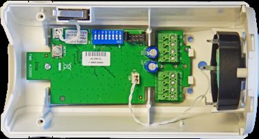
Indice
IT

     Generalità.......................................................................................................... 2
       Funzione del manuale.................................................................................................. 2
     Introduzione...................................................................................................... 3
         Funzionamento............................................................................................................. 3
     Caratteristiche tecniche.................................................................................. 4
     Descrizione dei componenti............................................................................ 5
         Generatore di fumo...................................................................................................... 5
         Circuito elettronico e contenitore fumogeno................................................................ 5
             Switch di programmazione.......................................................................................................6

             Morsettiera...............................................................................................................................6
     Programmazione del dispositivo.................................................................... 7
       Funzione di avvio della sirena...................................................................................... 9
       Programmazione durata del suono sirena................................................................. 11
       Funzione AND degli ingressi...................................................................................... 11
       Tamper antiapertura e antistrappo............................................................................. 11
       Significato del LED..................................................................................................... 11
       Stato delle uscite a morsettiera................................................................................. 13
       Stato di TEST e MANUTENZIONE............................................................................. 13
     Procedura di montaggio e rimozione........................................................... 14
         Preparazione del generatore di fumo......................................................................... 14
         Assemblaggio............................................................................................................ 14
         Rimozione.................................................................................................................. 14

      Generalità

     Si invita prima di tutto a leggere attentamente le Informazioni sulla Sicurezza che sono state fornite
     in formato cartaceo a corredo del prodotto al momento della vendita.
     Comelit Group S.p.A. declina ogni responsabilità in caso di non osservanza delle Informazioni sulla
     Sicurezza presenti sul prodotto.

     Funzione del manuale
     Il prodotto ed il presente manuale devono essere esaminati prima di effettuare qualsiasi operazione.
     Le informazioni contenute in questo manuale sostituiscono quanto precedentemente pubblicato.
     Comelit Group S.p.A. si riserva il diritto di modificare e di effettuare miglioramenti sul prodotto in
     qualsiasi momento e senza alcun preavviso.
     Nessuna parte di questo documento può essere riprodotta in alcuna forma senza permesso scritto
     di Comelit Group S.p.A.

     2
Introduzione
Il fumogeno Comelit è un accessorio per sistemi di allarme da utilizzare in sistemi di allarme filari

                                                                                                            IT
generici. Lo scopo principale è quello di costituire un sistema di dissuasione durante gli eventi furto
o rapina attivando sia una sirena piezoelettrica ad alto potenziale, sia un fumogeno in grado di
riempire un ambiente fino ad un massimo di 100 metri cubi in circa 30 secondi.

        • Non installare l’apparato in ambienti adibiti a produzione, deposito e/o
          somministrazione di alimenti.
        • Non installare l’apparato in ambienti adibiti a produzione e/o deposito di materiali
          per cui la contaminazione da polveri, anche lieve, non è ammissibile.
        • Non installare l’apparato in locali dove possano essere presenti persone e/o
          animali che siano impossibilitati all’evacuazione in caso di erogazione del fumo.
        • Non installare l’apparato in posizione tale da rendere difficoltoso e/o pericoloso
          l’abbandono dei locali in caso di erogazione del fumo.
        • Una volta attivato il generatore di fumo non è possibile interrompere l’erogazione
          che perdura fino all’esaurimento del contenuto.
        • In caso di attivazione arieggiare i locali entro 1 ora dall’erogazione del fumo.
        Comelit Group S.p.A. declina ogni responsabilità in caso di non osservanza delle
        indicazioni riportate in questo manuale e nelle Informazioni sulla Sicurezza.

Funzionamento
Il dispositivo può essere connesso ad una centrale di allarme tramite collegamenti elettrici filari che
possono arrivare ad una distanza massima di 200 m.
Il fumogeno è costituito da un robusto contenitore plastico dove al suo interno sono alloggiati il
circuito elettronico di controllo, la sirena piezoelettrica e il Generatore di fumo corredato dal proprio
circuito di attivazione. Il circuito elettronico è fornito di morsettiera estraibile a 8 poli dove sono
presenti i seguenti collegamenti:

• VCC			                             alimentazione (polo positivo)
• Ingresso Avvio Fumogeno            modalità di avvio programmabile
• Ingresso Avvio Sirena              modalità di avvio programmabile
• Uscita Tamper / Antistrappo        contatto NC riferito a GND in condizioni
  			                                di contenitore chiuso.
• Uscita generatore di fumo esaurito contatto NC riferito a GND con
          			generatore di fumo integro
• Uscita Errore     		contatto NC riferito a GND con
          			funzionamento regolare
• GND 			alimentazione (polo negativo) e
          			iferimento di tensione per ingressi

Il dispositivo consente una facile installazione indicando in tempo reale lo stato dell’apparato
mediante l’illuminazione di un LED multicolore.
Onde evitare attivazioni involontarie del generatore di fumo durante l’installazione, l’apparato
riconosce l’apertura del tamper e dopo 15 secondi entra in modalità di “TEST e MANUTENZIONE”.
In questa fase viene disabilitata l’attivazione del Generatore di fumo ed una eventuale attivazione
accidentale viene dirottata sul suono della sirena. Questa funzione può essere utilizzata anche
come test del sistema. L’uscita dallo stato di “TEST e MANUTENZIONE” si ottiene 15 secondi
dopo la chiusura del contenitore con il TAMPER e l’antistrappo (se abilitato) nello stato di riposo.
Un range di alimentazione che può andare da circa 3Vcc a 15 Vcc ed un basso assorbimento di
circa 200 uA a riposo, consentono di utilizzare il dispositivo in qualsiasi sistema di sicurezza

                                                                                                        3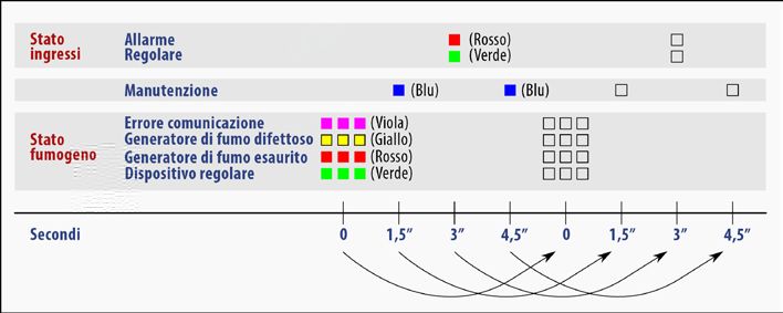
Caratteristiche tecniche
IT

         Tensione di alimentazione:              3,6 Vcc ÷ 15,0 Vcc con protezione da inversione di
                                                 polarità
         Assorbimento                            3,600V÷7,999V: ~180μA
                                                 8,000V÷15,000V: ~220μA
                                                 (con LED disabilitati)
         Assorbimento all’avvio:                 a 12V: max 150mA per 2s
                                                 a 3,6V: max 400mA per 2s
         Range di tensione sugli ingressi:
                                                 0,0 ÷ 15,0 Vcc
         Livello logico “1” sugli ingressi:
                                                 > 3Vcc
         Livello logico “0” sugli ingressi:
                                                 < 2Vcc
         Tempo minimo di attivazione:
                                                 1 s (ingresso fumogeno, ingresso sirena)
         Impedenza ingresso fumogeno e sirena:
                                                 ~4kΩ
         Uscite Generatore di fumo esaurito e    NC (open collector con riferimento a GND corrente
         errore:                                 max. 100 mA.)
         Autonomia:                              Il dispositivo dispone di accumulatori di energia tali
                                                 da mantenerlo in funzione anche se viene a mancare
                                                 l’alimentazione. Tale autonomia garantisce che il
                                                 dispositivo sia regolarmente funzionante fino a 4 ore
                                                 dopo la perdita di alimentazione
         Uscita Tamper e Antistrappo:            NC (contatto riferito a GND) Antistrappo disabilitabile
                                                 tramite SW-5
         Supervisione continua di:               Generatore di fumo valido, Generatore di fumo
                                                 difettoso, Generatore di fumo esaurito, circuito
                                                 attivazione generatore di fumo presente
         Potenza sonora sirena piezoelettrica
                                                 > 95 dB(A) @ 1m
         Durata media erogazione fumo:
                                                 Da 30 a 45 s
         Volume saturabile:
                                                 100 m3
         Altezza consigliata per il montaggio:
                                                 Da 2,10 a 2,30m da terra
         Sostituzione generatore di fumo:
                                                 Consigliato ogni 3 anni
         Led segnalazione:                       Led multicolore indicazione di stato ingressi, stato
                                                 Generatore di fumo e manutenzione
         Temperatura funzionamento:
                                                 0°C ÷ +45°C
         Temperatura di immagazzinamento:
                                                 -20°C ÷ +55°C
         Grado di protezione contenitore:
                                                 IP 30
         Dimensioni e peso:                      175x120x95 mm, 800g Generatore di fumo incluso

     4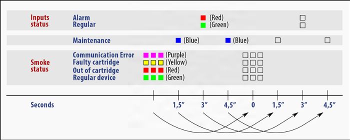
Descrizione dei componenti
Generatore di fumo

                                                                                       IT
                   Circuito di           Connettore
                  attivazione

                 Cartuccia
        generatore di fumo

Circuito elettronico e contenitore fumogeno
    1                                3
                             2                  1     Tamper
                                                2     Connettore di collegamento
                                                      alla cartuccia
                                                3     Sirena Piezoelettrica
                                                4     Pulsante di reset
                                                5     Dip-Switch programmazione
                                                6     Morsettiera cablaggio

              4          5       6

                                              Fori di fissaggio

                                              Passaggio cavo

                                              Fori di fissaggio

                                              LED stato

                                                                                   5
Switch di programmazione
IT

         SW-1 - Attivazione fumogeno      Fare riferimento al paragrafo
                                          “Funzione di avvio del fumogeno”
                                          per la programmazione

         SW-2 - Attivazione sirena        Fare riferimento al paragrafo
                                          “Funzione di avvio della sirena” per
                                          la programmazione

         SW-3 - Polarità ingressi         Fare riferimento ai paragrafi
                                          “Funzione di avvio del fumogeno” e
                                          “Funzione di avvio della sirena” per
                                          la programmazione

         SW-4 - Tempo sirena        ON    Segue input sirena
                                    OFF   60 secondi (Default)

         SW-5 - Antistrappo         ON    Abilitato (Default)
                                    OFF   Disabilitato

         SW-6     -   Funzione ON         Attiva (Default)
         AND
                                    OFF   Disattiva

         SW-7 - Abilitazione ON           Attiva (Default)
         LED
                             OFF          Disattiva

         SW-8 - Non utilizzato

         Morsettiera

         GND           GND
         IN SIR        Ingresso avvio sirena
         GND           GND
         IN FUM        Ingresso avvio fumogeno
         OUT TAMP      Uscita tamper
         OUT END       Uscita generatore di fumo esaurito
         OUT ERR       Uscita errore / guasto
         VCC           Ingresso tensione di alimentazione

     6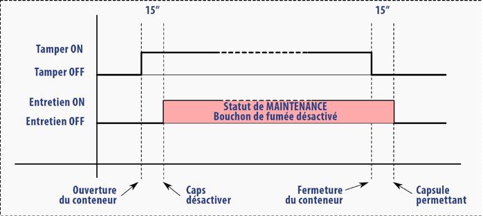
Programmazione del dispositivo
Le funzioni del dispositivo FG100F possono essere configurate tramite il settaggio degli switch

                                                                                                           IT
di programmazione presenti sul circuito. Di seguito sono riportate le descrizioni delle diverse
modalità di funzionamento.

• ATTENZIONE! Il dispositivo è dotato di accumulo di energia di riserva in caso di perdita di
  alimentazione. A seconda della funzione di avvio utilizzata (vedere paragrafo “Funzione di
  avvio del fumogeno” e “Funzione di avvio della sirena”), anche in assenza di alimentazione
  esterna, uno stato di allarme sugli ingressi può portare all’attivazione del fumogeno o
  della sirena.

Funzione di avvio del fumogeno
L’attivazione del fumogeno avviene portando l’ingresso IN FUM nello stato di allarme. Nel caso
sia attiva la funzione AND (SW-6 ad ON) per attivare il fumogeno l’ingresso IN FUM deve essere
portato nello stato di allarme mentre l’ingresso IN SIR si trova già nello stato di allarme. Lo stato di
allarme dell’ingresso IN FUM è programmabile tramite gli switch di programmazione SW-1 e SW-3.

• ATTENZIONE! In qualsiasi modalità di funzionamento, l’installatore deve assicurarsi
  che la mancanza di alimentazione ai dispositivi di controllo (ad es. centrale di allarme o
  sensori di presenza), non provochi variazioni degli ingressi del FG100F tali da innescare
  un’attivazione indesiderata del rilascio del fumo. Particolare attenzione deve essere posta
  con le configurazioni Positivo e Negativo a TOGLIERE.

Di seguito le combinazioni possibili e le corrispondenti modalità di funzionamento:

Positivo a dare - Normalmente aperto verso un positivo

 ON       ON
                        IN FUM

                                             Stato a riposo:
                                             ingresso IN FUM con contatto aperto
SW-1 SW-3                  +Vhi
                      (3÷15Vcc)

                        IN FUM
                                             Stato allarmato:
                                             ingresso IN FUM in stato logico “1” (contatto chiuso a
                                             tensione superiore alla tensione minima di stato logico
                           +Vhi              “1”)
                      (3÷15Vcc)

                                                                                                       7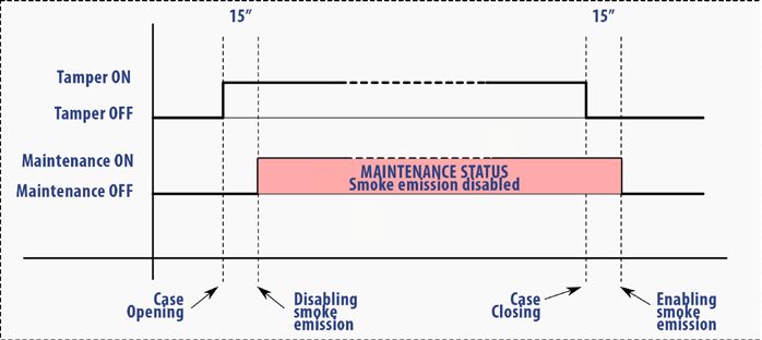
Negativo a dare - Normalmente aperto verso un negativo
IT

         ON     ON       IN FUM

                                             Stato a riposo:
                                             ingresso IN FUM con contatto aperto
         SW-1 SW-3         GND

                         IN FUM
                                             Stato allarmato:
                                             ingresso IN FUM in stato logico “0” (contatto chiuso
                                             a tensione inferiore alla tensione massima di stato
                           GND               logico “0”)

     Positivo a togliere - Normalmente chiuso verso un positivo

         ON     ON         IN FUM
                                             Stato a riposo:
                                             ingresso IN FUM in stato logico “1” (contatto chiuso
                                             a tensione superiore alla tensione minima di stato
         SW-1 SW-3            +Vhi           logico “1”)
                         (3÷15Vcc)

                           IN FUM

                                             Stato allarmato:
                                             ingresso IN FUM con contatto aperto
                              +Vhi
                         (3÷15Vcc)

     Negativo a togliere - Normalmente chiuso verso un negativo

         ON     ON        IN FUM
                                             Stato a riposo:
                                             ingresso IN FUM in stato logico “0” (contatto chiuso
                                             a tensione inferiore alla tensione massima di stato
                                             logico “0”)
         SW-1 SW-3          GND

                         IN FUM

                                             Stato allarmato:
                                             ingresso IN FUM con contatto aperto
                           GND

     8
Funzione di avvio della sirena
L’attivazione della sirena avviene allarmando l’ingresso IN SIR. Lo stato di allarme dell’ingresso IN
IT
SIR è programmabile tramite gli switch di programmazione SW-2 e SW-3.
• ATTENZIONE! In qualsiasi modalità di funzionamento, l’installatore deve assicurarsi
che la mancanza di alimentazione ai dispositivi di controllo (ad es. centrale di allarme o
sensori di presenza), non provochi variazioni degli ingressi del FG100F tali da innescare
un’attivazione indesiderata del rilascio del fumo. Particolare attenzione deve essere posta
con le configurazioni Positivo e Negativo a TOGLIERE.
Queste sono le possibili combinazioni e le corrispondenti modalità di funzionamento:
Positivo a dare - Normalmente aperto verso un positivo
ON ON IN SIR
Stato a riposo: ingresso IN SIR con contatto aperto
SW-2 SW-3 +Vhi
(3÷15Vcc)
IN SIR
Stato allarmato: ingresso IN SIR in stato logico “1”
(contatto chiuso a tensione superiore alla tensione
+Vhi
minima di stato logico “1”)
(3÷15Vcc)
Negativo a dare - Normalmente aperto verso un negativo
ON ON IN SIR
Stato a riposo: ingresso IN SIR con contatto aperto
SW-2 SW-3 GND
IN SIR
Stato allarmato: ingresso IN SIR in stato logico “0”
(contatto chiuso a tensione inferiore alla tensione
massima di stato logico “0”)
GND
9Positivo a togliere - Normalmente chiuso verso un positivo
IT
ON ON IN SIR
Stato a riposo: ingresso IN SIR in stato logico “1”
(contatto chiuso a tensione superiore alla tensione
minima di stato logico “1”)
SW-2 SW-3 +Vhi
(3÷15Vcc)
IN SIR
Stato allarmato: ingresso IN SIR con contatto aperto
+Vhi
(3÷15Vcc)
Negativo a togliere - Normalmente chiuso verso un negativo
ON ON IN SIR
Stato a riposo: ingresso IN SIR in stato logico “0”
(contatto chiuso a tensione inferiore alla tensione
massima di stato logico “0”)
SW-2 SW-3 GND
IN SIR
Stato allarmato: ingresso IN SIR con contatto aperto
GND
10Programmazione durata del suono sirena
Il tempo di suono della sirena piezoelettrica può essere programmato tramite lo switch SW4 del
IT
Tempo Sirena secondo la seguente tabella:
Segue lo stato dell’ingresso Avvio Sirena
ON
SW-4 (tempo di suono max. 15 minuti)
OFF 60 secondi
Funzione AND degli ingressi
Tramite lo switch SW6 è possibile scegliere il modo di attivazione del fumogeno secondo la
seguente tabella:
Il generatore di fumo viene attivato solo se l’ingresso IN FUM viene allarmato
ON
mentre l’ingresso IN SIR è già allarmato
SW-6
Il generatore di fumo viene attivato immediatamente quando l’ingresso IN
OFF
FUM viene allarmato
Tamper antiapertura e antistrappo
Il tamper antiapertura e antistrappo fanno riferimento ad una unica uscita OUT TAMP con
riferimento a massa nella posizione di contenitore chiuso.
Il controllo antistrappo può essere abilitato/disabilitato tramite lo switch SW5 come da tabella:
ON Abilitato
SW-5
OFF Disabilitato
Significato del LED
L’attività e lo stato del dispositivo, e lo stato delle uscite “GENERATORE DI FUMO ESAURITO”
e “ERRORE”, vengono evidenziate tramite un LED multicolore presente nella parte inferiore della
scocca. Come illustrato dal seguente schema, le informazioni vengono presentate con lampeggi di
vari colori, organizzati in un ciclo che ha durata di 6 secondi (4 fasi con intervallo di 1,5 s tra l’una
e l’altra).
11Passo n.1 (t = 0 s): 3 lampeggi
IT
Verde Generatore di fumo regolarmente funzionante
Rosso Generatore di fumo esaurito (cartuccia già usata)
Giallo Generatore di fumo difettoso
Errore di comunicazione con il circuito di attivazione del generatore di fumo
Viola (probabile mancanza di collegamento elettrico o assenza del Generatore di
fumo)
Passo n.2 (t = 1.5 s): singolo lampeggio (o nessun lampeggio)
Blu Il dispositivo è in modalità “TEST e MANUTENZIONE”.
Nessun Il dispositivo non è in modalità “TEST e MANUTENZIONE”. Il dispositivo è
lampeggio pronto all’attivazione.
Passo n.3 (t = 3 s): singolo lampeggio
Entrambi gli ingressi (Fumogeno e Sirena) sono in stato di riposo (nessun
Verde
allarme).
Rosso Almeno uno dei due ingressi è attivato (allarme).
Passo n.4 (t = 4.5 s): singolo lampeggio (o nessun lampeggio)
Blu Il dispositivo è in modalità “TEST e MANUTENZIONE”.
Nessun Il dispositivo non è in modalità “TEST e MANUTENZIONE”. Il dispositivo è
lampeggio pronto all’attivazione.
Il LED può essere disabilitato impostando lo switch SW-7 su OFF riducendo ulteriormente il
consumo di energia.
Ulteriori funzioni del LED sono:
• Lampeggio continuo di colore bianco durante il suono della sirena.
• Lampeggio continuo di colore rosso se il dispositivo è in modalità “TEST e MANUTENZIONE”
e viene attivato il fumogeno.
12Stato delle uscite a morsettiera
Tipo di segnalazione Uscita Generatore di fumo Uscita errore
IT
esaurito (OUT END) (OUT ERR)
Dispositivo regolare GND GND
Errore di comunicazione GND OPEN
Generatore di fumo difettoso OPEN OPEN
Generatore di fumo esaurito OPEN GND
Errore generico GND OPEN
Stato di TEST e MANUTENZIONE
Questo stato viene attivato automaticamente alla prima alimentazione premendo il pulsante di
RESET e tutte le volte in cui viene aperto il contenitore. Lo stato di “TEST e MANUTENZIONE”
cessa alla chiusura del contenitore. Una temporizzazione di 15 secondi sia all’apertura che alla
chiusura del contenitore, evita la possibilità di sabotaggio dell’apparato.
Durante questo stato:
• Il LED emette un lampeggio di colore BLU ogni 3 secondi
• L’attivazione del fumogeno (rilascio del fumo) non è permessa.
• Il passaggio dell’ingresso IN FUM nello stato di attivazione, provoca un suono CONTINUO della
sirena, della durata di 3 secondi, abbinato al lampeggio veloce del LED ROSSO.
• Il passaggio dell’ingresso IN SIR nello stato di attivazione, provoca un suono MODULATO della
sirena, della durata di 3 secondi, abbinato al lampeggio veloce del LED ROSSO.
Utilizzando questa caratteristica, è possibile testare i collegamenti fra centrale di allarme e
fumogeno escludendo il rischio dell’attivazione del generatore di fumo.
• ATTENZIONE: nel caso si decida di utilizzare il Generatore di fumo con la funzione AND
attivata (SW6 = ON), si consiglia di effettuare il test di corretto cablaggio disabilitando questa
funzione, e di provare singolarmente la corretta gestione dei 2 ingressi. Successivamente
riabilitare la funzione AND. Si ricorda che il cambiamento di uno o più dip-switch deve
essere seguito dalla pressione del tasto RESET per applicare la configurazione.
Il seguente schema temporale mostra il comportamento dello stato di “TEST e MANUTENZIONE”
13Procedura di montaggio e rimozione
Preparazione del generatore di fumo
IT
Le fasi di assemblaggio e collegamento necessarie per la preparazione del generatore di fumo
sono nel manuale allegato allo stesso.
• Attenzione! La sostituzione del generatore di fumo comporta anche la sostituzione del
circuito di attivazione.
Assemblaggio
• Fissare il contenitore alla parete rispettando un’altezza da 2,10
a 2,30m da terra.
2,30m • Cablare l’alimentazione e i segnali di avvio e di controllo.
• Posizionare i dip-switch secondo le impostazioni desiderate.
• Alimentare il dispositivo (senza cartuccia inserita e collegata).
• Verificare il funzionamento controllando il lampeggio del LED
di stato che dovrà mostrare le seguenti indicazioni:
◦ 3 lampeggi VIOLA (errore per assenza della cartuccia del
generatore di fumo)
2,10m
◦ 1 lampeggio BLU (Stato di Test e Manutenzione)
◦ 1 lampeggio VERDE (Stato regolare degli ingressi)
◦ 1 lampeggio BLU (Stato di Test e Manutenzione)
• Collegare la cartuccia del generatore di fumo mediante
l’apposito connettore e posizionarla nell’alloggiamento.
• Verificare lo stato del generatore di fumo con i 3 lampeggi LED
VERDE ad indicare lo stato di REGOLARITÀ.
• Chiudere il coperchio con le viti in dotazione
• Inserire la fascia di copertura viti.
• Attendere l’uscita dallo stato di TEST e MANUTENZIONE con
l’assenza del lampeggio del LED BLU.
• Il fumogeno è pronto all’uso.
Rimozione
Eseguire le operazioni necessarie a garantire che il sabotaggio
del dispositivo non porti all’attivazione dello stesso (ad esempio
mettendo la centralina collegata in manutenzione)
• Aprire il contenitore
• Portare lo switch SW-7 su ON attivando il lampeggio dei LED
• Premere il tasto RESET o attendere che il dispositivo entri in
modalità “TEST e MANUTENZIONE” (LED BLU lampeggiante )
• Disalimentare il dispositivo
• Da questo momento in poi è possibile rimuovere il dispositivo in sicurezza o sostituire la capsula
ATTENZIONE! Non disalimentare il dispositivo prima di averlo messo in modalità “TEST e
MANUTENZIONE”. Il dispositivo dispone un’autonomia di funzionamento anche in assenza
di alimentazione. Disalimentarlo prima di averlo messo in manutenzione può portare
all’attivazione dello stesso.
14GARANZIA
IT
• La garanzia sui prodotti elettrici e/o elettronici di produzione Comelit è di 24 mesi dalla data di acquisto
ovvero dalla data indicata dalla fattura.
• La presente garanzia non si estende ai software prodotti e/o commercializzati da Comelit Group S.p.A., né
copre gli eventuali danni di qualsiasi natura che possono derivare dal loro uso ed utilizzo.
• Qualora i prodotti o parti di essi risultano difettosi per qualità dei materiali o per anomalie di costruzione,
la garanzia è limitata alla loro sostituzione. Sono comprese nella garanzia suddetta le prestazioni di
manodopera necessarie alle riparazioni.
• Nel caso in cui l’apparato difettoso risulti mancante di una o più parti, verrà riparato e restituito senza
integrare le stesse, salvo esplicita richiesta in tal senso.
• La presente garanzia non si estende alle avarie dipendenti dall’usura naturale dei prodotti o di parti di essi
(ivi incluse le batterie).
• La presente garanzia non copre i danni causati da negligenza ed incuria, da sinistro, dall’uso improprio
dei prodotti, o di parti di essi, e/o dei software; così i danni causati da agenti atmosferici, da esposizione
dei medesimi prodotti, o parti di essi, e/o dei software a condizioni ambientali improprie, ivi inclusi i danni
direttamente o indirettamente provocati da temperatura eccessi va, umidità, stress fisici od elettrici,
mancanza o fluttuazione di energia elettrica, fulmini, elettricità statica, incendi, inondazioni o allagamenti, e
da quanto non imputabile alla diretta responsabilità di Comelit Group S.p.A.
• Sono esclusi dalla copertura della garanzia anche i danni imputabili a cattiva od erronea installazione – ossia
installazione non conforme alle relative istruzioni od in assenza di esse non effettuata a regola d’arte – per
errata o carente manutenzione secondo quanto indicato nelle relative istruzioni d’uso o comunque secondo
l’usuale manutenzione, per operazioni o uso improprio o errato, per trascuratezza o incapacità d’uso e
comunque per cause di ogni genere non dipendenti da Comelit Group S.p.A.
• Sono esclusi dalla copertura della presente garanzia tutti quei danni prodotti da difetti originari di componenti
o di parti del prodotto assemblate, comunque certificati, che non sia possibile in alcun modo rilevare prima,
durante e dopo la realizzazione del prodotto finale da parte di Comelit Group S.p.A., secondo le normali e
consuete procedure di controllo e di verifica dei componenti o di prodotti e parti di essi esterni; altresì, i
danni o i difetti imputabili a riparazioni ed a manutenzioni, così come a sostituzioni o modificazioni, effettuate
da soggetti terzi, non autorizzati direttamente dal produttore, in ogni caso da altri con prodotti, o parti di essi,
e/o software, diversi, non originali, non conformi e quindi non garantiti, non certificati approvati ed autorizzati
da Comelit Group S.p.A.
• In ogni caso non sono coperti dalla garanzia i danni ed i difetti che risultino dall’utilizzo, non preventivamente
ed espressamente autorizzato da Comelit Group S.p.A., di ricambi ed accessori non compatibili, non
originali, non conformi, non certificati ed approvati dal produttore medesimo, nonché tutti quei danni
imputabili a qualsiasi modifica del prodotto o di parti di essi e/o del software, che non sia stata, in alcun
modo, assentita dal produttore; o, comunque, dovuti a cause di forza maggiore e/o caso fortuito.
• Comelit Group S.p.A. si riserva il diritto di apportare modifiche alle condizioni di garanzia sopra elencate,
senza alcun obbligo di preavviso. Saranno, in ogni caso, valide le condizioni vigenti al momento dell’acquisto
del prodotto elettrico e/o elettronico di produzione Comelit Group S.p.A.
15INDEX
General information....................................................................................... 16
Function of the manual.............................................................................................. 16
Introduction..................................................................................................... 17
EN
Operation................................................................................................................... 17
Data sheets..................................................................................................... 18
Description of the components.................................................................... 19
Smoke generator........................................................................................................ 19
Electronic circuit and smoke generator enclosure .................................................... 19
Programming Dip-Switch...................................................................................................... 20
Terminal block....................................................................................................................... 20
Device programming...................................................................................... 21
Smoke generator function.......................................................................................... 21
Siren function............................................................................................................. 23
Programming siren sound duration............................................................................ 25
AND function for inputs............................................................................................. 25
Anti-opening and anti-tear Tamper............................................................................ 25
Meaning of LED......................................................................................................... 25
Status of terminal outputs.......................................................................................... 27
TEST and MAINTENANCE status.............................................................................. 27
Installation and remove procedure............................................................... 28
Smoke generator setup.............................................................................................. 28
Assembly................................................................................................................... 28
Removal..................................................................................................................... 28
General information
The product and this manual must be examined before performing any operation.
The information in this manual was verified during the writing of the manual itself, however Comelit
Group S.p.A. reserves the right to modify and make improvements to the product described at any
time without any warning.
Function of the manual
Before carrying out any operations, the product and the present manual must be thoroughly
checked.
All information contained in this manual have been checked and verified, during the issuing of
the manual itself. However, Comelit Group S.p.A. shall have the right to modify and improve the
product described, at any time without further notice.
No part of this document may be reproduced without permission from Comelit Group S.p.A. All
rights reserved.
16Introduction
The Comelit smoke generator is an accessory for alarm systems to be used on generic wired alarm
systems.
The main purpose is to set up a deterrence system during theft or robbery events activating both
a high-potential piezoelectric siren and a smoke generator that is able to fill an environment up to
100 cubic meters in about 30 seconds.
EN
• Do not install the equipment in areas used for food production, storage and/or
supplying.
• Do not install the equipment in areas used for the production and/or storage of
goods for which even slight dust contamination is not admissible.
• Do not install the equipment in rooms where people and/or animals that cannot
escape in case of smoke release may be present.
• Do not install the equipment in such a way as to make it difficult and/or dangerous
to leave the premises in case of smoke release.
• Once the smoke generator is activated, it is not possible to interrupt the delivery
which lasts until the content is exhausted.
• In the event of activation, ventilate the premises within 1 hour of smoke release.
Comelit Group S.p.A. declines all responsibility in the event of non-compliance with
the instructions given in this manual and in the Safety Information.
Operation
The device can be connected to an alarm system via an electrical cable connection that can reach
a maximum distance of 200 meters.
The smoke generator consists of a sturdy plastic enclosure where the electronic control circuit,
the piezoelectric siren and the smoke generator accompanied by its own activation circuit are
housed inside. The electronic circuit is equipped with an 8-pole removable terminal block where
the following connections are present:
• VCC power supply (positive polarity)
• Start Smoking Input programmable startup mode
• Start Siren Input programmable start mode
• Tamper / Anti-tear Output NC contact referred to GND with closed enclosure.
• Used-up smoke generator NC contact referred to GND with full smoke generator
• Error Output NC contact referred to GND with regular operation
• GND power supply (negative polarity) and voltage reference
for inputs
The device allows an easy installation by indicating in real time the state of the apparatus by
lighting a multicolored LED. In order to avoid unwanted activations of the smoke generator during
installation, the apparatus recognizes the tamper opening and after 15 seconds enters “TEST and
MAINTENANCE” mode. At this stage, the activation of the smoke generator is disabled and any
accidental activation is diverted to the siren sound. This function can also be used as a system
test. The exit from the “TEST and MAINTENANCE” state is obtained 15 seconds after closing the
enclosure with the TAMPER and the anti-tear switches (if enabled) in closed position. A power
range of 3Vcc to 15 Vcc and a low current drain of about 200μA in the idle mode, allow you to use
the device in any security system.
17Data sheets
Power: From 3,0 ÷ 15,0 Vcc
Average current: 3,000V÷7,999V: ~180μA
8,000V÷15,000V: ~220μA
(with LEDs disabled)
EN
Power consumption at startup: at 12V: max 150mA for 2s
at 3,6V: max 400mA for 2s
Input voltage range: 0 ÷ 15,0 Vcc
Logic level “1” on inputs: >3Vcc
Logic level “0” on inputs: 95 dB(A) @ 1 m
Average duration of smoking: From 30 to 45 s
Saturable Volume: 100 m3
Recommended height for mounting: From 2,10 to 2,30m above the ground
Smoke generator replacement: Recommended every 3 years
Signalling LED: 2 Red LEDs for variation Status Inputs + 1 Red /
green LED for radio communication
Operating temperature: 0°C ÷ +45°C
Storage temperature: -20°C ÷ +55°C
Degree of container protection: IP 30
Size and weight: 175x120x95 mm, 800g smoke generator included
18Description of the components
Smoke generator
Activation circuit Connector
EN
Smoke generator
cartridge
Electronic circuit and smoke generator enclosure
1 3
2 1 Tamper
2 Smoke generator connection
cable
3 Piezoelectric siren
4 Reset button
5 Programming Dip-Switch
6 Wiring terminal board
4 5 6
Fixing holes
Cable entry
Fixing holes
Status LED
19Programming Dip-Switch
SW-1 - Smoke activation See paragraph “Smoke generator
function” for programming
SW-2 - Siren activation See paragraph “Siren function” for
programming
EN
SW-3 - Inputs polarity See paragraphs “Smoke generator
function” and “Siren function” for
programming.
SW-4 - Siren time ON Follow siren input ON time
OFF 60 seconds (Default)
SW-5 - Anti-tear ON Enabled (Default)
OFF Disabled
SW-6 - AND ON Enabled (Default)
function
OFF Disabled
SW-7 - Led ON Enabled (Default)
enabled
OFF Disabled
SW-8 - Not used
Terminal block
GND GND
IN SIR Siren enable input
GND GND
IN FUM Smoke enable input
OUT TAMP Tamper output
OUT END Used-up smoke generator output
OUT ERR Error / fault output
VCC Power input
20Device programming
FG100F device functions can be configured by setting programming switches on the circuit.
Following are descriptions of the various configuration mode.
• WARNING! The device is equipped with backup energy storage in case of power loss.
Depending on the start function used (see paragraphs “Smoke generator function” and
“Siren function”), even in the absence of external power, an alarm state on the inputs can
EN
lead to the activation of the smoke or siren.
Smoke generator function
The activation of the smoke generator takes place by bringing the IN FUM input to the alarm state.
If the AND function is active (SW-6 to ON) to activate the smoke generator, the IN FUM input must
be brought to the alarm state while the IN SIR input is already in the alarm state. The alarm status
of the IN FUM input can be programmed using the SW-1 and SW-3 programming switches.
• WARNING! In any operating mode, the installer must ensure that the absence of power to
the control devices (e.g. alarm control unit or presence sensors) does not cause changes
in the inputs of the FG100F such as to trigger an undesired activation of the smoke
release. Particular attention must be paid with the “Positive and Negative to REMOVE”
configurations.
These are the possible combinations and the corresponding operating modes:
Positive to give - Normally open to a positive
ON ON IN FUM
Rest state: IN FUM input with open contact
SW-1 SW-3 +Vhi
(3÷15Vcc)
IN FUM
Alarmed state: IN FUM input in logic state “1”
(contact closed at voltage higher than the minimum
+Vhi
voltage of logic state “1”)
(3÷15Vcc)
21Negative to give - Normally open to a negative
ON ON IN FUM
Rest state: IN FUM input with open contact
SW-1 SW-3 GND
EN
IN FUM
Alarmed state: IN FUM input in logic state “0” (contact
closed at voltage lower than the maximum voltage of logic
state “0”)
GND
Positive to remove - Normally closed to a positive
ON ON
IN FUM
Rest state: IN FUM input in logic state “1” (contact
closed at voltage higher than the minimum voltage of
SW-1 SW-3 +Vhi
logic state “1”)
(3÷15Vcc)
IN FUM
Alarmed state: IN FUM input with open contact
+Vhi
(3÷15Vcc)
Negative to remove - Normally closed to a negative
ON ON IN FUM
Rest state: IN FUM input in logic state “0” (contact open at
voltage lower than the maximum voltage of logic state “0”)
SW-1 SW-3 GND
IN FUM
Alarmed state: IN FUM input with closed contact
GND
22Siren function
The siren is activated by alarming the IN SIR input. The alarm status of the IN SIR input is
programmable using the SW-2 and SW-3 programming switches.
• WARNING! In any operating mode, the installer must ensure that the absence of power to
the control devices (e.g. alarm control unit or presence sensors) does not cause changes
EN
in the inputs of the FG100F such as to trigger an undesired activation of the smoke
release. Particular attention must be paid with the “Positive and Negative to REMOVE”
configurations.
These are the possible combinations and the corresponding operating modes:
Positive to give - Normally open to a positive
ON ON
IN SIR
Rest state: IN SIR input with open contact
SW-2 SW-3 +Vhi
(3÷15Vcc)
IN SIR
Alarmed state: IN SIR input in logic state “1” (contact
closed at voltage higher than the minimum voltage of
+Vhi
logic state “1”)
(3÷15Vcc)
Negative to give - Normally open to a negative
ON ON IN SIR
Rest state: IN SIR input with open contact
SW-2 SW-3 GND
IN SIR
Alarmed state: IN SIR input in logic state “0” (contact
closed at voltage lower than the maximum voltage of logic
state “0”)
GND
23Positive to remove - Normally closed to a positive
ON ON IN SIR
Rest state: IN SIR input in logic state “1” (contact closed
at voltage higher than the minimum voltage of logic state
“1”)
SW-2 SW-3 +Vhi
(3÷15Vcc)
EN
IN SIR
Alarmed state: IN SIR input with open contact
+Vhi
(3÷15Vcc)
Negative to remove - Normally closed to a negative
ON ON IN SIR
Rest state: IN SIR input in logic state “0” (open contact at
voltage lower than the maximum voltage of logic state “0”)
SW-2 SW-3 GND
IN SIR
Rest state: IN SIR input with closed contact
GND
24Programming siren sound duration
The sound time of the piezoelectric siren can be programmed via the SW4 switch of the Siren Time
according to the following table:
ON Follow Siren input ON time (max sound time 15 minutes)
SW-4
OFF 60 seconds
EN
AND function for inputs
Using the SW6 switch, you can choose how the smoke generator is activated according to the
following table:
The smoke generator is activated only if the smoke input IN FUM is alarmed
ON
when the siren input is already alarmed.
SW-6
The smoke generator is activated immediately when the smoke input IN FUM
OFF
is alarmed.
Anti-opening and anti-tear Tamper
The anti-opening and anti-tear tamper refer to a single OUT TAMP output. In Normal state (closed
enclosure and anti-tear switch engaged) the output is Normally Closed to a Zero Voltage (GND). In
case of anomaly, the output is an Open Contact.
Tear control can be enabled/disabled using the SW5 switch as per table:
ON Enabled
SW-5
OFF Disabled
Meaning of LED
The activity and status of the device are highlighted by a multicolor LED at the bottom of the body
and by the status of the outputs “USED-UP SMOKE GENERATOR” and “ERROR”.
According to the following scheme, the system status information is shown every 6 seconds.
251st step (t = 0 s): three blinks
Green Smoke generator regular state. No faulty conditions.
Red Used-up smoke generator .
Yellow Faulty smoke generator
Communication error with the smoke generator activation circuit (probable
Purple
EN
lack of electrical connection or smoke generator absence)
2nd step (t = 1,5 s): single blink (or no blink)
Blue The device is in “TEST and MAINTENANCE” mode.
The device is not in “TEST and MAINTENANCE” mode. The device is ready
No blink
for activation.
3rd step (t = 3 s): single blink
Green Both Smoke and Siren Inputs are in Normal state (No Alarm)
Red One or both Inputs are active (Alarm state)
4th step (t = 4,5 s): single blink (or no blink)
Blue The device is in “TEST and MAINTENANCE” mode.
The device is not in “TEST and MAINTENANCE” mode. The device is ready
No blink
for activation.
The LED can be disabled by setting the SW-7 switch to OFF further reducing energy consumption.
Additional LED functions are:
• Continuous flashing of white color during the sound of the siren.
• Continuous red flashing if the device is in TEST and MAINTENANCE modemand active and the
smoke generator us active.
26Status of terminal outputs
Reporting type Output Finish Smoke Error output
generator (OUT END) (OUT ERR)
Regular Device GND GND
Communication error GND OPEN
Faulty smoke generator OPEN OPEN
EN
Used-up smoke generator OPEN GND
Generic error GND OPEN
TEST and MAINTENANCE status
This mode is automatically activated, at first power-up, by pressing the RESET button, and
whenever the enclosure is opened. The “TEST and MAINTENANCE” mode is terminated when the
enclosure is closed. A 15-second timing at both the opening and closing of the enclosure avoids
the possibility of sabotage of the device.
When in this mode:
• a single BLUE flash blinks every 3 seconds.
• the smoke emission is disabled.
• if the IN FUM input is activated (alarm condition), the siren emits a CONTINUOUS sound, and
the RED LED blinks rapidly.
• if the IN SIR input is activated (alarm condition), the siren emits a MODULATED sound, and the
RED LED blinks rapidly.
Please enter this mode for checking cabling, connections, and dip-switches setup, without risks
of unwanted smoke emissions.
• Warning! When you want to activate the AND feature (SW6=ON), please perform tests by
first DISABLING this feature, and checking inputs one by one. Then RE-ENABLE the AND
feature. Please remember to push the RESET button after switching one or more dip-
switches, to apply the configuration.
The following time diagram shows the state behaviour of “TEST and SERVICE”.
27Installation and remove procedure
Smoke generator setup
The assembly and connection instructions, with necessary steps for the preparation of the smoke
generator cartridge, are reported in the manual attached to it.
• Warning! The replacement of the smoke generator also involves the replacement of the
EN
activation circuit.
2,30m
Assembly
• Fasten the enclosure to the wall with a height of 2.10 to 2.30
meters above the ground
• Connect power and I/O cables.
• Place the dip-switches according to the desired settings.
• Power-up the device (without the smoke cartridge).
2,10m • Check the operation by checking the status LED, that will
have to show the following indications:
◦ 3 PURPLE blinks (communication error due to lack of
smoke cartridge)
◦ 1 BLUE blink (Test and Maintenance mode)
◦ 1 GREEN blink (Regular status of inputs)
◦ 1 BLUE blink (Test and Maintenance mode)
• Connect the smoke generator cartridge, and place it in
position.
• Check the status of the smoke generator (3 GREEN blinks, to
indicate the REGULAR status).
• Close the lid with the screws provided.
• Insert the screw cover band.
• Wait the exit from the TEST and MAINTENANCE mode with
the stop of BLUE LED blinking.
• The smoke generator is ready to use.
Removal
Follow the operations necessary to ensure that the sabotage of
the device does not lead to the activation of the same (for example
putting the connected control unit in maintenance)
• Open the container
• Turn the SW-7 switch to ON by activating the flashing of the LEDs
• Press the RESET key or wait for the device to enter “TEST and MAINTENANCE” mode (BLUE
LED flashing)
• Disconnect the device
• From now on you can safely remove the device or replace the capsule
WARNING! Do not disconnect the device before putting it in “TEST and MAINTENANCE”
mode. The device has an autonomy of operation even in the absence of power supply.
Disconnecting it before putting it into maintenance can lead to activation of the same.
28CERTIFICATE OF GUARANTEE
• The guarantee on electrical and / or electronic products manufactured by Comelit Group S.p.A. is valid for
24 months from the purchase date, or from the date on the invoice.
EN
• This guarantee does not extend to the software produced and / or sold by Comelit Group S.p.A. , nor does
it cover damages of any kind that may derive from the use of the same.
• Should the products or parts of them prove faulty owing to the quality of the materials used or due to
anomalies that occurred during manufacturing, the guarantee limits to the replacement of said products or
parts. The above guarantee includes costs of labor necessary to carry out repairs.
• In cases where one or more parts of the faulty device are missing, the device will be repaired and returned
to the client without integration of missing pieces, excepting when there is an explicit request for integration.
• This guarantee does not extend to malfunctions due to normal wear and tear of the products or their parts
(including batteries).
• This guarantee does not cover damages caused by negligence, carelessness, accidents or improper use of
the products or parts of the same and / or the software. The same applies to damage caused by atmospheric
agents, exposure of the products or their parts, and / or of the software, to inappropriate environmental
conditions, including damages caused, either directly or indirectly, by excessive temperature, dampness,
physical or electrical stress, electrical blackout or power surges, lightning, static electricity, fires, floods and
any other circumstances that are not ascribable to the direct responsibility of Comelit Group S.p.A. .
• This guarantee does not cover damages caused by poor or incorrect installation - or installation that is not
compliant with the relevant instructions or - lacking the same - installation carried out in an unprofessional
manner, wrong or poor maintenance interventions in accordance with what is indicated in the relevant
operating instructions or according to usual maintenance practice, improper or wrong operation, negligence
or lack of ability to use the product correctly or indeed other causes of any kind that are not ascribable to
Comelit Group S.p.A. .
• This guarantee does not cover any damage originating from faults in assembled components or parts of the
product, although certified in any manner, that it is not possible for Comelit Group S.p.A. to identify in any
way in advance, during or after the manufacturing of the end product in accordance with the normal checking
and verification procedures applied for components or products and external parts of them. Damages or
defects ascribable to repair and maintenance interventions, replacements or changes carried out by third
parties not directly authorized by the manufacturer, or carried out by others employing unoriginal or non-
compliant products, parts of products and / or software that are therefore not guaranteed, not certified and
not approved or authorized by Comelit Group S.p.A., are not covered by this guarantee.
• In any case, damages and faults arising from the use of spare parts and accessories that are non-
compatible, unoriginal, non-compliant, uncertified and not approved by the manufacturer are not covered
by this guarantee. Same applies to all damages ascribable to changes made to the product or parts of the
same and / or to the software that are in no way approved by the manufacturer or due to causes of force
majeure and / or unforeseeable circumstances.
• Comelit Group S.p.A. reserves the right to make amendments to these guarantee conditions without prior
notice. In any case, the conditions in force at the time of purchase of the electric and / or electronic product
manufactured by Comelit Group S.p.A. will be considered valid.
29INDEX
Généralités...................................................................................................... 30
Généralités..................................................................................................................30
Fonction manuelle.......................................................................................................30
Introduction..................................................................................................... 31
Opération....................................................................................................................31
Spécifications ................................................................................................ 32
Description des composants........................................................................ 33
Générateur de fumée..................................................................................................33
FR
Circuit électronique et récipient de fumée..................................................................33
Commutateur de programmation.......................................................................................... 34
Bornier de câblage................................................................................................................ 34
Programmation de l’appareil......................................................................... 35
Fonction de démarrage fumée....................................................................................35
Fonction de démarrage sirène....................................................................................37
Durée sonore des sirènes de programmation.............................................................39
AND fonction des entrées...........................................................................................39
Tamper anti-ouverture et anti-enlèvement..................................................................39
Signification de LED....................................................................................................39
État des sorties terminales..........................................................................................41
L’état TEST et MAINTENANCE...................................................................................41
Procédure d’installation et de retrait............................................................ 42
Préparation de générateur de fumées.........................................................................42
Assemblée..................................................................................................................42
Retrait..........................................................................................................................42
Généralités
Généralités
Tout d’abord, nous vous invitons à lire attentivement les informations de sécurité fournies au format
papier et accompagnant le produit au moment de la vente.
Comelit Group S.p.A. décline toute responsabilité en cas de non-respect des informations de
sécurité figurant sur le produit.
Fonction manuelle
Avant d’effectuer une quelconque opération, le produit et le présent manuel devront être examinés.
Bien que les informations contenues dans ce manuel aient été vérifiées durant sa rédaction,
Comelit Group S.p.A. se réserve le droit, à tout moment et sans aucun préavis, d’apporter des
modifications ou des améliorations au produit qui y est décrit.
Aucune partie de ce document ne peut être reproduite sans l’autorisation de Comelit Group S.p.A..
Tous droits réservés.
30Introduction
Le fumigène Comelit est un accessoire pour les systèmes d’alarme à utiliser sur les systèmes
génériques.
L’objectif principal est de mettre en place un système de dissuasion lors d’événements de vol ou
de vol l’activation à la fois d’une sirène piézoélectrique à fort potentiel et le fumigène capable de
remplir un environnement jusqu’à 100 mètres cubes en 30 secondes environ
• N’installez pas l’équipement dans des environnements utilisés pour la production, le
stockage et / ou l’administration d’aliments.
• N’installez pas l’équipement dans des zones utilisées pour la production et/ou le
stockage de matériaux pour lesquels une légère contamination par la poussière n’est
pas admissible.
• N’installez pas l’équipement dans des pièces où des personnes et/ou des animaux qui
FR
ne peuvent pas s’échapper en cas de dégagement de fumée peuvent être présents.
• N’installez pas l’appareil de manière à rendre difficile et/ou dangereux de quitter les
pièces en cas de dégagement de fumée.
• Une fois le générateur de fumée activé, il n’est pas possible d’interrompre la livraison
qui dure jusqu’à épuisement du contenu.
• En cas d’activation, ventiler les locaux dans les 1 heure suivant le dégagement de fumée.
• Le Comelit Group S.p.A. décline toute responsabilité en cas de non-respect des
instructions données dans ce manuel et dans les Informations de Sécurité.
Opération
L’appareil peut être connecté à une usine d’alarme par des connexions électriques en rangée qui
peuvent atteindre une distance maximale de 200 mètres.
Le fumigène se compose d’un récipient en plastique robuste où le circuit de contrôle électronique,
la sirène piézoélectrique et la générateur de fumée accompagnée de son propre circuit d’activation
sont logés à l’intérieur.
Le circuit électronique est équipé d’une borniere amovible de 8 potes où les connexions suivantes
sont présentes :
• VCC Alimentation VCC (pôle positif)
• Entrée de démarrage de la fumée Mode de démarrage programmable
• Entrée Siren Start Mode de démarrage programmable
• Sortie de tamper / anti-enlèvement Le contact NC fait référence à GND dans des
conditions de conteneur fermé.
• Sortie de générateur de fumée périmée Contact NC référencé à GND avec
générateur de fumée intact
• Sortie d’erreur Contact NC référé à GND avec
fonctionnement régulier
• GND alimentation (pôle négatif) et référence de
tension pour les entrées
L’appareil permet une installation facile en indiquant en temps réel l’état de l’appareil en allumant
une LED multicolore.
Pour éviter les activations involontaires de la générateur de fumée pendant l’installation, l’appareil
reconnaît l’ouverture de la falsification et, après 15 secondes, entre en mode TEST et SERVALING.
À ce stade, l’activation de la générateur de fumée est désactivée et toute activation accidentelle
est détournée vers le son de la sirène. Cette fonction peut également être utilisée comme un test
système. La sortie de l’état “TEST et MAINTENANCE” est obtenue 15 secondes après la fermeture
du conteneur avec le TAMPER et l’anti-déchirure (si activé) dans l’état de repos. Une plage de
puissance de 3Vcc à 15 Vcc et une faible absorption d’environ 200 uA au repos, vous permettent
d’utiliser l’appareil dans n’importe quel système de sécurité.
31Puoi anche leggere