MANUALE OPERATIVO OPERATING MANUAL - INDICATORE DIGITALE DIGITAL INDICATOR
←
→
Trascrizione del contenuto della pagina
Se il tuo browser non visualizza correttamente la pagina, ti preghiamo di leggere il contenuto della pagina quaggiù
INDICATORE DIGITALE
      DIGITAL INDICATOR

   MANUALE OPERATIVO
   OPERATING MANUAL
         MO.MP1.508.R7

                                       Wimesure
                                       54, rue de Versailles • 78460 CHEVREUSE • Tél. 01 30 47 22 00 • Fax 01 30 47 28 29
41126 Cognento (MODENA) Italy Via Bottego 33/A Tel:+39-(0)59-346441
                                       www.wimesure.fr                  Fax:+39-(0)59-346437 E-mail: aep@aep.it
                                                           • info@wimesure.fr
MP1 Manuale operativo - Operating manual MO.MP1.508.R7
DICHIARAZIONE DI CONFORMITA' DECLARATION OF CONFORMITY
Costruttore: AEP transducers s.r.l Manufacturer: AEP transducers s.r.l
Indirizzo: Via Bottego 33/A 41126 Cognento MODENA (Italia) Address: Via Bottego 33/A 41126 Cognento MODENA (Italy)
DICHIARA CHE IL SEGUENTE PRODOTTO DECLARES THAT THE FOLLOWING PRODUCT
Nome del prodotto: MP1 Product name: MP1
Tipo: Indicatore Digitale Anno di costruzione: 2006 Type: Digital Indicator Year of manufacturing: 2006
Opzioni: questa dichiarazione copre tutte le opzioni specificate nel Options: this declaration covers all the options specified in the sales
catalogo di vendita. catalogue.
È CONFORME ALLE SEGUENTI DIRETTIVE CONFORM TO THE FOLLOWING DIRECTIVES
2004/108/CE - 2006/95/CE - 2002/95/CE - 2002/96/CE 2004/108/CE - 2006/95/CE - 2002/95/CE - 2002/96/CE
E' CONFORME ALLE SEGUENTI NORME CONFORMS TO THE FOLLOWING NORMS
EN 61010-1(2001) EN 61326-1(2007) EN 61010-1(2001) EN 61326-1(2007)
E' CONFORME AL REGOLAMENTO n° 1907/2006 (REACH) CONFORMS TO THE REGULATION n° 1907/2006 (REACH)
Il prodotto e' stato provato nella configurazione tipica di installazione The product has been tested in the typical installation configuration, as
descritta nel manuale di istruzioni. Il prodotto soddisfa i requisiti delle described in the instruction manual. Above described product meets the
Norme citate, sulla base dei risultati delle prove e delle valutazioni requirements of mentioned Norms, basing on both test results and
descritte nel Fascicolo Tecnico. considerations listed in the technical file.
Io sottoscritto dichiaro che il prodotto sopra descritto soddisfa i requisiti I declare that the product defined above meets the requirements of the
delle Direttive, delle Norme e dei Regolamenti sopra citati. Directives, of the Norms and Rules above mentioned.
41126 Cognento MODENA Lioi Giovanni 41126 Cognento MODENA Lioi Giovanni
Direttore Tecnico Technical Manager
Data: 31-07-2009 Date: 31-07-2009
Pag. 1MP1 Manuale operativo - Operating manual MO.MP1.508.R7
INDICE GENERALE GENERAL INDEX Pag. / Page
Targa di Identificazione - Usi non previsti - Smaltimento Identification Plate - Unauthorized uses - Disposal 4
Introduzione Introduction 5
- Diagramma a blocchi - Descrizione del hardware - Block diagram - Hardware description 6
Dati Tecnici Technical Data 7
- Dati di Riferimento - Configurazione di default - Codici acquisto - Reference Data - Default Configuration - Purchase code 9
- Trasporto - Consegna - Posizionamento - Installazzione - Transport - Delivery - Positioning - Installation 10
- Accensione - Spegnimento - Manutenzione - Indicazioni - Power On - Power Off - Maintenance - Displays 11
Calibrazione dello strumento Instrument calibration 12
- Descrizione dei Tasti - Keys description 13
Menu Impostazioni Setting Menu 14
- Set-Point - Set-Point 15
- Isteresi dei Set-Point - Set-Points Hysteresis 16
- Come modificare direttamente i Set Point - How to modify directly the Set Point 16
Password - Parametri protetti da Password Password - Protected parameters by Password 17
- Risoluzione di misura - Measurement Resolution 17
- Filtri Digitali - Digital Filters 18
- Picco - Peak 18
- Soppressione della Tara - Tare suppression 19
- Fondo Scala (dello strumento) - Full Scale (of the instrument) 19
- Punto Decimale - Decimal Point 20
- Ingresso Analogico - Analog Input 20
Uscita Analogica Analog Output 21
- Regolazione di Zero, Fondo Scala e Ampiezza - Zero, Full Scale and Amplitude adjust 22/23
Pag. 2MP1 Manuale operativo - Operating manual MO.MP1.508.R7
- Ingresso Digitale - Digital Input 23
- Sensibilità Ingresso Analogico - Analog Input Sensibility 24
- Ripristino della Calibrazione di fabbrica - Company Calibration restoration 24
Funzioni - Descrizione Functions - Descriptions
- Zero - Zero 25
- Picco - Peak 25
- Hold - Hold 25
Istruzioni per il montaggio - Dimensioni Mounting instructions - Dimensions 26
Collegamenti Connections
- Alimentazione - Power supply 27
- Celle di carico e trasduttori a 4 fili - Load cells and transducers with 4 wires 28
- Trasmettitori con uscita amplificata a 2 o 3 fili - Transmitters with amplified output 2 or 3 wires 29
- Uscite a relay - Relay output 30
- Ingresso Digitale - Digital Input 31
- Uscita analogica - Analog output 32
Sonda PT100 (collegamenti e caratteristiche funzionali) PT100 Probe (connections and functional characteristics) 33
Messaggi errore - Ricerca guasti Error Messages - Trouble shooting 34
L'AEP transducers si riserva il diritto, qualora lo ritenesse necessario, di apportare AEP transducers holds the right to make any change, when necessary, without
modifiche di qualsiasi genere senza alcun obbligo di preavviso. I dati contenuti in notice. The data contained in this manual are just indicative and the
questo manuale sono indicativi, la ditta declina ogni responsabilità per errori o manufacturer declines any responsibility for errors or discrepancies with respect
discordanze dal presente. to this manual.
Pag. 3MP1 Manuale operativo - Operating manual MO.MP1.508.R7
TARGA DI IDENTIFICAZIONE IDENTIFICATION PLATE
Sul contenitore dello strumento, sono marcate in modo indelebile tutte le On the instrument enclosure, are marked in indelible mode all the
informazioni per l’identificazione, i principali dati di configurazione, i information for the identification, the main configuration data, the symbols
simboli di conformità e smaltimento, la data di produzione. of conformity and waste disposal, the production date.
USI NON PREVISTI UNAUTHORIZED USES
Ambienti con atmosfera esplosiva. Environments with explosive atmosphere.
Ambienti con gas infiammabili o corrosivi. Environments with inflammable or corrosive gas.
SMALTIMENTO DISPOSAL
Lo strumento è una apparecchiatura professionale, conforme alle The instrument is a professional apparatus compliant to the
Direttive 2002/95/CE (RoHS) e 2002/96/CE (RAEE), deve essere Directives 2002/95/CE (RoHS) and 2002/96/CE (WEEE), then it
smaltito separatamente come rifiuto elettrico ed elettronico. must be disposed separately as electric and electronic waste.
In paesi diversi dalla Comunità Europea deve essere smaltito In different countries of European Community, it must be
come rifiuto elettrico ed elettronico in accordo con le leggi del disposed as waste electric and electronic in accord to the laws of
paese dove lo strumento è commercializzato. the country where the device is commercialized.
Prima di rimuovere lo strumento, togliere l'alimentazione poi Before to remove the instrument, you disconnect first the power
scollegare i cavi. supply and after the cables.
Pag. 4MP1 Manuale operativo - Operating manual MO.MP1.508.R7
INTRODUZIONE INTRODUCTION
L’indicatore digitale MP1 é uno strumento idoneo a ricevere in ingresso MP1 digital indicator is a instrument suitable for receiving input signals
segnali provenienti da Strain Gauge a ponte intero oppure da trasduttori coming either form full bridge strain gauge or transducers with amplified
con uscita amplificata in tensione o corrente, è indicato per la misura di output in voltage or in current, it is recommended for the measurement of
forze, peso e pressione. Realizzato per essere impiegato in sistemi di forces, weight and pressures. Designed to be employed in industrial field
misura statica e dinamica in ambiente industriale può campionare il static and dynamic measurement systems, it can sample the signal up to
segnale fino ad una frequenza di 300Hz. a frequency of 300Hz.
Strumento di accuratezza ≤0.05% ha una risoluzione standard di ±9999 Instrument with an accuracy of ≤0.05% it has a standard resolution of
divisioni ed una risoluzione interna di ±19999 divisioni. ±9999 divisions and a internal resolution of ±19999 divisions.
Idoneo ad utilizzare celle di carico o dinamometri da 350/700Ω con Suitable to use load cells or dynamometers from 350/700Ω with a 4 wires
collegamento a 4 fili, trasduttori con uscita 0÷10V, 4÷20mA oppure system connection, pressure transducers with 0÷10V or 4÷20mA output
potenziometri. L'ingresso da cella di carico è raziometrico, mentre gli or potentiometers. Load cell input is ratiometric while the pressure
ingressi da trasduttore sono gestiti con una sorgente di riferimento. transducers inputs are managed with a reference source. The analog
L'uscita analogica (a richiesta) e l'ingresso digitale non sono optoisolati. output (on request) and the remote digital input are not optoinsulated.
L'uscita analogica è programmabile per le uscite: ±10V, 0÷20mA, The analog output is programmable for the outputs ±10V, 0÷20mA,
4÷20mA; il suo Fondo Scala è indipendente dal Fondo Scala dello 4÷20mA; your Full Scale is independent from the instrument Full Scale,
strumento, lo zero e l'ampiezza sono regolabili da tastiera. the zero and the amplitude are adjusted through the keyboard.
L'ingresso digitale remoto è associato alla funzione di Zero, Picco o The remote digital input is associated to Zero, Hold or Peak function
Hold in accordo con la selezione da tastiera. according to the selection made through the keyboard.
I Set-point hanno l'uscita a relay ed hanno la soglia di attivazione e The Set-points have a relay output and the activation threshold and the
l'isteresi di disattivazione programmabile. deactivation hysteresis are programmable.
La sensibilità dell'ingresso analogico è programmabile (1.000÷3.000mV) The analog input sensitivity is programmable (1.000÷3.000mV) and
e rende facile il collegamento di celle di carico con uscita non calibrata. makes the connection of load cells with not calibrated output easier.
Pag. 5MP1 Manuale operativo - Operating manual MO.MP1.508.R7
DIAGRAMMA A BLOCCHI BLOCKS DIAGRAM
DESCRIZIONE del HARDWARE HARDWARE DESCRIPTION
Lo strumento è gestito da un Microcontrollore a 8 bit in tecnologia flash The instrument is managed by a 8 bit Microcontroller in flash technology
che controlla tutto il sistema attraverso le sue periferiche interne. Esegue which controls all the system through its internal peripherals. It performs
i calcoli sul segnale campionato dal ADC, mostra il valore sul display e lo the calculations on the ADC sampled signal, then it shows the value on
invia all'uscita Analogica, gestisce i tasti. the display and sends it to the Analog output, it manages the keys.
La cella di carico è alimentata a 5Vdc, i trasduttori a 15Vdc. The load cell is fed a 5Vdc, while the transducers at 15Vdc.
Convertitore Analogico Digitale: Analog to Digital Converter:
Componente intelligente in tecnologia sigma/delta, amplifica e campiona A intelligent component in sigma/delta technology, amplifies and samples
il segnale fino ad una frequenza di 300Hz. Il valore campionato è the signal up to a frequency of 300Hz. Sampled value is ratiometric by
raziometrico per l'ingresso da cella di carico mentre è proporzionale al load cell input while it is proportional to the reference signal by amplified
segnale di riferimento per l'ingresso amplificato. input.
Software: Il programma esegue tutte le funzioni dello strumento. Software: The software performs all the instrument functions.
Pag. 6MP1 Manuale operativo - Operating manual MO.MP1.508.R7
DATI TECNICI TECHNICAL DATA
INGRESSO CELLA DI CARICO - Campo di misura LOAD CELL INPUT - Measurement range ±1.000mV/V ÷ 3.000mV/V
RISOLUZIONE INGRESSO STANDARD (± 2mV/V) STANDARD INPUT RESOLUTION (± 2mV/V) ±9999 div
DIVISIONI INTERNE INTERNAL DIVISIONS ±19999 div
DINAMOMETRI COLLEGABILI CONNECTABLE DYNAMOMETERS 4/8 by 350/700Ω
TRASDUTTORI COLLEGABILI CONNECTABLE TANSDUCERS 1 by 35mA
ECCITAZIONE DINAMOMETRI DYNAMOMETERS EXCITATION 5Vdc(±3%)
ALIMENTAZIONE TRASDUTTORI TRANSDUCERS POWER SUPPLY 15Vdc(±3%)
MASSIMA VELOCITA' DI CONVERSIONE MAX CONVERSION SPEED 300Hz (3.3mS)
(con Filtro=0 e Uscita Analogica=Disabilitata) (with Filter=0 and Analog output=Disabled)
IMPEDENZA Ingresso Analogico amplificato Amplified Analog Input IMPEDANCE >1MΩ
CLASSE DI PRECISIONE ACCURACY CLASS ≤±0.05%
ERRORE DI LINEARITA' LINEARITY ERROR ≤±0.05%
TEMPERATURA LAVORO NOMINALE NOMINAL TEMPERATURE RANGE 0... +50°C
TEMPERATURA LAVORO MASSIMA MAX TEMPERATURE RANGE 0... +50°C
TEMPERATURA DI STOCCAGGIO STORAGE TEMPERATURE RANGE -20... +70°C
EFFETTI VARIAZIONI DI TEMP. 10°C EFFECTS ON A 10°C TEMP. VARIATION
a) sullo zero a) on zero ≤±0.01%
b) sul fondo scala b) on full scale ≤±0.01%
CAMPO DI INDICAZIONE INDICATION RANGE max ± 9999 div
FUNZIONE DI ZERO ZERO FUNCTION 100%
RISOLUZIONE PROGRAMMABILE PROGRAMMABLE RESOLUTION 1 2 5 10 20 50 100
DECIMALI PROGRAMMABILI PROGRAMMABLE DECIMAL POINTS 3
FILTRI DIGITALI PROGRAMMABILI PROGRAMMABLE DIGITAL FILTERS 5
INGRESSO DIGITALE SELEZIONABILE (non isolato) SELECTABLE DIGITAL INPUT (not insulated) Zero, Peak or Hold
Pag. 7MP1 Manuale operativo - Operating manual MO.MP1.508.R7
ALIMENTAZIONE GENERALE GENERAL POWER SUPPLY 230 Vac ±10%
FREQUENZA FREQUENCY 50/60Hz
POTENZA MASSIMA MAX POWER ACCEPTED 115/230Vac: 5VA
12Vdc: 2.2W 24Vdc: 4.4W
RELE' DI USCITA (carico resistivo) OUTPUT RELAY (resistive load) 115Vac 0,2A or 48Vdc 0,2A
TEMPO DI ECCITAZIONE EXCITATION TIME max 7mS
GRADO DI PROTEZIONE (solo pannello frontale) PROTECTION CLASS (front panel only) IP40 (EN 60529)
DIMENSIONI (AxLxP) DIMENSIONS (HxLxD) 48x96x153mm
DIMA DI FORATURA (AxL) mm HOLE GAUGE (HxL) mm 44.5x91.5
PESO WEIGHT ∼ 0.5kg
SCATOLA CASE NORYL UL94 V-O
PANNELLO ANTERIORE e POSTERIORE FRONT and BACK PANEL UL94 V-2
OPZIONI OPTIONS
ALIMENTAZIONE POWER SUPPLY 115Vac ±10%
12Vdc(±10%) 24Vdc(15÷28V)
INGRESSO AMPLIFICATO - Campo di misura AMPLIFIED INPUT - Measurement range 0÷20mA, 4÷20mA, 0÷10V
INGRESSO da SONDA PT100 (2 fili) PT100 PROBE INPUT (2 wires) range:-10÷120°C accuracy ±0.5%
USCITA ANALOGICA non isolata in TENSIONE VOLTAGE not insulated ANALOG OUTPUT ±10V (RL ≥ 10KΩ)
USCITA ANALOGICA non isolata in CORRENTE CURRENT not insulated ANALOG OUTPUT 0÷20mA 4÷20mA (RL ≤ 500Ω)
RISOLUZIONE INTERNA INTERNAL RESOLUTION ±14 bit
CARATTERISTICHE USCITA ANALOGICA ANALOG OUTPUT CHARACTERISTICS Rise and Fall time: 25÷2500mS
Ripple:MP1 Manuale operativo - Operating manual MO.MP1.508.R7
DATI DI RIFERIMENTO REFERENCE DATA
Temperatura Temperature + 23°C
Umidità relativa Relative humidity + 50%
Sensibilità segnale d’ingresso Input Signal Sensitivity 2mV/V
Fondo Scala Full Scale ±9999 div
Risoluzione Resolution 1
Filtro digitale Digital filter 2
CONFIGURAZIONE DI DEFAULT DEFAULT CONFIGURATION
USCITA ANALOGICA (a richiesta) 0÷20mA ANALOG OUTPUT (on request) 0÷20mA
FILTRO DIGITALE 2 DIGITAL FILTER 2
RISOLUZIONE 1 RESOLUTION 1
PUNTO DECIMALE no DECIMAL POINT no
FONDO SCALA STRUMENTO ±9999 INSTRUMENT FULL SCALE ±9999
SENSIBILITA' INGRESSO ANALOGICO 2.000mV ANALOG INPUT SENSITIVITY 2.000mV
TASTO DI ZERO Abilitato ZERO KEY Enabled
INGRESSO DIGITALE Zero DIGITAL INPUT Zero
CODIFICA PER L'ACQUISTO PURCHASE CODE
Codice Alimentazione Uscita Analogica Code Power supply Analog output
EMP1 A230 = 230Vac O4 = 4-20mA EMP1 A230 = 230Vac O4 = 4-20mA
A115 = 115Vac O5 = ±5V A115 = 115Vac O5 = ±5V
D24 = 24Vdc O10 = ±10V D24 = 24Vdc O10 = ±10V
Pag. 9MP1 Manuale operativo - Operating manual MO.MP1.508.R7
TRASPORTO TRANSPORT
La componentistica é elettronica. In caso di trasporto imballare The device is made of electronic components. In case of transport pack it
adeguatamente lo strumento. Attenzione ai forti urti e all’umidità. carefully. Pay attention to both strong shocks and humidity.
CONSEGNA DELIVERY
Lo strumento viene collaudato in ogni particolare, configurato e calibrato Instrument is tested in any of its parts, it is supplied configurated and
con le specifiche del cliente oppure con la configurazione di default calibrated according to customer specifications or default configuration
(pag.9). (page 9).
POSIZIONAMENTO POSITIONING
Lo strumento é da pannello. Non è da tavolo. Instrument is designed for built-in purposes. It isn’t a desktop equipment.
Posizionare in luogo illuminato e adeguatamente protetto dagli agenti It shall be housed in a well ligthed position and protected by atmospherics
atmosferici. agents.
INSTALLAZIONE INSTALLATION
Questo strumento è stato prodotto in conformità alle norme per la This instrument has been manufactured according to both EMC
Compatibilità Elettromagnetica e la Sicurezza delle Apparecchiature a (Electromagnetic Compatibility) regulations and to Low Voltage
Bassa Tensione; affinché esse siano rispettate è necessario eseguire i Equipment Safety, in order to have such rules respected it is necessary
collegamenti elettrici secondo quanto indicato nel presente manuale e to perform electrical connections according to what mentioned in this
dalle marcature presenti sullo strumento. manual and to what written on instrument labels.
Lo strumento è da pannello, per il montaggio utilizzare gli appositi Instrument is designed for built-in purposes, for its mounting use the
accessori forniti con lo strumento (pag.26). accesories supplied with the instrument (page 26).
L'installazione deve essere eseguita da personale istruito. Installation shall be done by authorized personnel only.
Pag. 10MP1 Manuale operativo - Operating manual MO.MP1.508.R7
ACCENSIONE POWER ON
Lo strumento non dispone di interruttore. Collegare lo strumento tramite Instrument does not have any switch. Connect the instrument to the
l’apposita morsettiera alla rete elettrica; la protezione dalle sovracorrenti terminal board to the electric net; protection against overcurrent shall be
deve essere eseguita con fusibili esterni (pag.29). Collegare i segnali di performed through external fuses (page 29). Connect I/O signals to the
I/O alla apposita morsettiera (pag.27÷32). Alimentare la rete elettrica. provided terminal board (pages 27÷32). Feed the electric net.
L'accensione deve essere fatta da personale istruito. Per una Power must be done by authorized personnel only.
migliore accuratezza della misura è consigliabile che lo strumento For a better reading accuracy it is advisable that the instrument
raggiunga la sua stabilità termica (~15 minuti). reach his thermal stability (about 15 minutes).
SPEGNIMENTO POWER OFF
Togliere alimentazione alla rete elettrica. Disconnect the electric net.
MANUTENZIONE MAINTENANCE
Lo strumento non richiede manutenzione periodica; in caso di mal Instrument doesn’t require periodic maintenance; in case of faulty
funzionamento, contattare il fornitore. functioning, please contact the supplier.
Occasionalmente pulire il pannello anteriore con panno non abrasivo Clean occasionally instrument front panel with a non-abrasive cloth
imbevuto di sostanze non corrosive. soaked with non-corrosive substances.
La manutenzione deve essere fatta da personale informato. Maintenance shall be done by authorized personnel only.
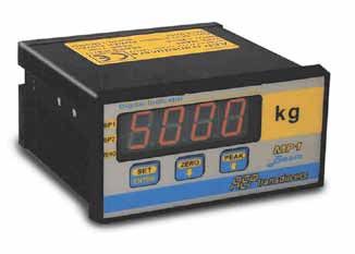
INDICAZIONI DISPLAYS
All’accensione lo strumento mostra la versione software (fig.1) per circa 3 At its starting, instrument displays software version (pict.1) for about 3
secondi, quindi si posiziona in pagina principale pronto a rispondere ai seconds, then instrument goes to the main page and it is ready to
comandi dell’operatore (fig.2). Nel caso si verifichi un funzionamento perform operator commands (pict.2). If something, different from above
diverso da quello sopra descritto consultare a pag.33/34. described procedures, happens please go to page 33/34.
Le indicazioni vengono mostrate su un display a 7 segmenti rossi. Indications are displayed by a red 7 segments display.
fig.1 esempio pagina iniziale fig.2 esempio di pagina principale
r 1.3 pict. 1 start page example 500.0 pict. 2 main page example
Pag. 11MP1 Manuale operativo - Operating manual MO.MP1.508.R7
CALIBRAZIONE dello STRUMENTO INSTRUMENT CALIBRATION
Lo strumento è consegnato già calibrato come richiesto dal cliente o con i The instrument is delivered already calibrated as customer request or
parametri di default; per cambiare la calibrazione è sufficiente cambiare il with the default parameter; to change the calibration is sufficient to
Fondo Scala (pag.19) con la portata nominale della cella di carico o del change the Full Scale (page 19) with the nominal range of the connected
trasduttore di pressione collegato, automaticamente lo strumento load cell or pressure transducer, automatically the instrument will indicate
indicherà la misura corretta. the correct measurement.
Esempio: 1 cella da 1000kg -> Fondo Scala = 1000 Example: 1 load cell from 1000kg -> Full Scale = 1000
2 celle da 1000kg -> Fondo Scala = 2000 2 load cells from 1000kg -> Full Scale = 2000
trasduttore da 500 bar -> Fondo Scala = 500 oppure 500.0 transducer from 500 bar - > Full Scale = 500 or 500.0
trasduttore da 250 bar -> Fondo Scala = 250 oppure 250.0 transducer from 250 bar -> Full Scale = 250 or 250.0
Se la cella di carico ha l'uscita diversa da 2mV, prima impostare il Fondo If the load cell has a different output from 2mV, first select the Full Scale
Scala poi modificare il parametro Sensibilità ingresso analogico (pag.24). then modify the analog input Sensibility (page 24) parameter.
Esempio: 1mV=1.000, 2mV=2.000(default), 3mV=3.000, 1.5mV=1.500 Example: 1mV=1.000, 2mV=2.000(default), 3mV=3.000, 1.5mV=1.500
Per azzerare lo strumento ci sono due funzioni: To reset the instrument there are two functions:
• Tara (pag.19) consigliata per grosse quantità (serbatoio, ecc.). • Tare (page 19) we advise for a great quantity (tank, etc.).
• Zero (pag.13, 25) consigliata per piccole quantità (offset trasduttori, • Zero (page 13, 25) we advise for small quantity (transducer offset,
ecc..) oppure per azzerare direttamente la misura. etc.) or to reset the measurement directly.
I parametri di Tara, Fondo Scala e Sensibilità, sono accessibili nel Menu Tare, Full Scale and Sensibility parameters, are available in the protected
protetto tramite la password 0007. Menu through the 0007 password.
Le funzioni Tara e Zero azzerano la misura in modo permanente. Tare and Zero functions reset the measurement in permanent mode.
Per inserire lo Zero, premere il tasto Zero. To make the Zero, to push the Zero key.
Per togliere lo Zero, premere il tasto Zero per circa 3 secondi. To remove the Zero, to push about 3 seconds the Zero key.
Per ripristinare la calibrazione di default, usare la password 4256 (pag.24) To restore the default calibration, to use the 4256 password (page 24).
Pag. 12MP1 Manuale operativo - Operating manual MO.MP1.508.R7
DESCRIZIONE dei TASTI KEYS DESCRIPTIONS
I comandi dello strumento sono formati da 3 tasti posti sul pannello Commands for indicator use consist of a 3 keys placed on instrument
frontale; le funzioni dei tasti sono indicate dalla grafica sul pannello. front panel; keys functions are showed by the graphic on the panel.
Questo tasto esegue tre funzioni: This key has three functions:
SET 1) SET: dalla pagina principale, se premuto per 3 secondi 1) SET: from the main page, if pushed for 3 seconds it
entra nel Menu per l’impostazione dei dati. enters into the Menu for data setting.
ENTER 2) SET: dalla pagina principale, se premuto uno o due volte 2) SET: from the main page, if pushed one o two time it
entra direttamente nel Set Point1 o Set Point2. enters directly to Set Point1 or Set Point2.
3) ENTER: dentro al Menu memorizza il dato e mostra il 3) ENTER: inside the Menu it stores the data and shows the
parametro successivo, dopo l'ultimo parametro ritorna alla next parameter, after the last parameter it comes back to
pagina principale. the main page.
Questo tasto esegue due funzioni: This key has two functions:
ZERO 1) Nella pagina principale attiva la funzione di Zero, se 1) In the main page it activates the Zero, function, if pushed
premuto per 3 secondi disattiva la funzione (pag.25). for 3 seconds it deactivates the function (page 25).
Con la password 3101 il tasto di Zero può essere abilitato With the 3101 password the Zero key can be enabled or
o disabilitato. disabled.
2) Nel Menù decrementa ( ) il valore o il carattere sul 2) In the Menu it decreases ( ) the value or the character
display. on the display.
Questo tasto esegue due funzioni: This key has two functions:
PEAK 1) In pagina principale attiva o disattiva la funzione di Picco 1) In the main page it activates or deactivates the Peak
(pag.25). function (page 25).
2) Nel Menù incrementa ( ) il valore o il carattere sul 2) In the Menu it increases ( ) the value or the character on
display. the display.
Pag. 13MP1 Manuale operativo - Operating manual MO.MP1.508.R7
MENU IMPOSTAZIONI SETTING MENU
Lo strumento, se non diversamente specificato dal cliente, viene fornito Instrument, unless nothing different is specified by customer, is supplied
con la configurazione di default (pag.9); per personalizzare lo strumento è with default configuration (page 9); in order to customize the instrument it
necessario configurare i parametri di seguito elencati. is necessary to set below listed parameters.
Come configurare lo strumento: How to set the instrument:
1) Nella pagina principale premere il tasto Set per 3 secondi, sul 1) In the main page press Set key for 3 seconds, on the display the
display compare la prima pagina del Menu (fig.3). first Menu page appears (pict.3).
2) Premere il tasto Enter per memorizzare il dato e passare al 2) Press Enter key to store the data and go to the next parameter; to
parametro successivo; per entrare nel Menu protetto, avanzare fino enter in the protected Menu, you advance until the P000 parameter
al passo P000 (fig.4), impostare la password 0007 e premere il tasto (pict.4), select the 0007 password and press the Enter key to
Enter per confermare. confirm.
3) Per uscire dal Menu premere ripetutamente il tasto Enter fino a 3) To exit from the Menu press repeatedly Enter key until the main
ritornare alla pagina principale (pag.11 fig.2). page appears (page 11 pict.2).
Come Impostare i Parametri: How to set the parameters:
1) ENTER = memorizza il dato; mostra il parametro successivo. 1) ENTER = to store the data; to show the next parameter.
2) = incrementa la cifra o il carattere, se tenuto premuto, dopo 2 2) = to increase the digit or the character selected, if kept pressed,
secondi incrementa rapidamente il valore. after 2 seconds, it rapidly increases the value.
3) = decrementa la cifra o il carattere, se tenuto premuto, dopo 2 3) = to decrease the digit or the character selected, if kept pressed,
secondi decrementa rapidamente il valore. after 2 seconds, it rapidly decreases the value
fig.3 prima pagina del Menù fig.4 pagina di accesso al Menù protetto
SP1P pict.3 first page Menù P000 pict.4 protected Menu access page
Pag. 14MP1 Manuale operativo - Operating manual MO.MP1.508.R7
SET POINT 1 e 2 SET POINT 1 and 2
SP1P=Set-point 1 campo Positivo SP1n=Set-point 1 campo Negativo SP1P=Set-point 1 Positive field SP1n=Set-point 1 Negative field
SP2P=Set-point 2 campo Positivo SP2n=Set-point 2 campo Negativo SP2P=Set-point 2 Positive field SP2n=Set-point 2 Negative field
÷9999
Valori Impostabili: 0÷ Selectable values: 0÷9999
Quando il valore campionato raggiunge il valore del Set-point, si attiva When sampled value reaches the Set-point value, the corresponding
l’uscita a relay corrispondente e si accende il led corrispondente alla relay output activates and the led corresponding to the graphic indication
indicazione grafica sul pannello. All’accensione i Set-point vengono on the panel switches on. At instrument starting, set points are activated
attivati in ritardo per permettere allo strumento di stabilizzarsi. later in order to enable the digital indicator to stabilize itself.
Come impostare i Set-point: How to set the Set-points:
Con i tasti di incremento ( ) e decremento ( ) impostare il valore To the increase ( ) and decrease ( ) keys set the wanted value, press
desiderato, premere il tasto ENTER per confermare. ENTER key to confirm.
Indicazione Set-point 1 campo Positivo Indicazione Set-point 1 campo Negativo
SP1P Positive field Set-point 1 indication SP1n Negative field Set-point 1 indication
Indicazione Set-point 2 campo Positivo Indicazione Set-point 2 campo Negativo
SP2P Positive field Set-point 2 indication SP2n Negative field Set-point 1 indication
Valore di default Set-point 1 Valore di default Set-point 2
1000 Set-point 1 default value 2000 Set-point 2 default value
Pag. 15MP1 Manuale operativo - Operating manual MO.MP1.508.R7
ISTERESI 1 e 2 HYSTERESIS 1 and 2
Valori Impostabili: 000 ÷ 999 Selectable values: 000 ÷ 999
Determina il valore di disattivazione del Set Point(n): (n)=1 o 2 . To calculate the value of Set Point(n) deactivation: (n)=1 or 2.
Valore di Disattivazione = (val.Set Point(n) - val.Isteresi(n)). Deactivation value = (Set Point(n) value - Hysteresis(n) value).
Es.: se Set Point=1000 e Isteresi=10 Disattivazione=(1000-10)=990 Ex.: if Set Point=1000 and Hysteresis=10 Deactivation=(1000-10)=990
Viene disattivata l’uscita del relay R(n) e viene spento il led del Set-Point R(n) relay output is deactivated and the Set-point(n) corresponding led is
corrispondente. switched off.
Come selezionare l'isteresi dei Set-point: How to select the hysteresis of the Set-points:
Con i tasti di incremento ( ) e decremento ( ) impostare il valore To the increase ( ) and decrease ( ) keys set the wanted value, press
desiderato, premere il tasto ENTER per confermare. ENTER key to confirm.
Indicazione Isteresi di Set-point 1 Valore di default Isteresi 1
Hy 1 Set-point 1 hysteresis indication 010 Hysteresis 1 default value
Indicazione Isteresi di Set-point 2 Valore di default Isteresi 2
Hy 2 Set-point 2 hysteresis indication 010 Hysteresis 2 default value
COME MODIFICARE DIRETTAMENTE I SET POINT HOW TO MODIFY DIRECTLY THE SET POINT
1) Set Point1: nella pagina principale premete il tasto SET, sul display 1) Set Point1: in the main page you push SET key, on the display
compare il valore, con i tasti e modificate il valore, poi premete appears the value, with and keys you change the value, then
il tasto ENTER per memorizzare il dato e passare al Set Point2. you push ENTER key to store the data and to go to Set Point2.
2) Set Point2: nella pagina principale premete due volte il tasto SET, 2) Set Point2: in the main page you push two time SET key, on the
sul display compare il valore, con i tasti e modificate il valore, display appears the value, with and keys you change the value,
premete il tasto ENTER per memorizzare il dato ed uscire dal Menu. you push the ENTER key to store the data and to go out from Menu.
Pag. 16MP1 Manuale operativo - Operating manual MO.MP1.508.R7
PASSWORD PASSWORD
Password 0007: accede ai parametri protetti dello strumento. Password 0007: to enter to the protected parameters of the instrument.
Passoword 3101: abilita o disabilita il tasto di Zero. Password 3101: it enabled or disabled the Zero key.
Password 4256: ripristina la Calibrazione di fabbrica. Password 4256: it restore the default calibration.
Come impostare la Password: How to set the Password:
Con i tasti di incremento ( ) e decremento ( ) impostare il valore To the increase ( ) and decrease ( ) keys set the wanted value, press
desiderato, premere il tasto ENTER per confermare. ENTER key to confirm.
Pagina di impostazione della Password Password di accesso al Menu protetto
P000 Password setting page 0007 Protected Menu access password
PARAMETRI PROTETTI da PASSWORD 0007 PROTECTED PARAMETERS by 0007 PASSWORD
RISOLUZIONE DI MISURA MEASUREMENT RESOLUTION
Valori selezionabili: 1 2 5 10 20 50 100 Selectable values: 1 2 5 10 20 50 100
La Risoluzione definisce la costante di incremento delle ultime cifre. The Resolution defines the constant of the last digits increase.
Si usa per aumentare la stabilità di misura. It is used to increase the measurement stability.
Come impostare la Risoluzione di Misura: How to set the measurement Resolution:
Con i tasti di incremento ( ) e decremento ( ) selezionare il valore To the increse ( ) and decrease ( ) keys set the wanted value, press
desiderato, premere il tasto ENTER per confermare. ENTER key to confirm.
Pagina di impostazione della Risoluzione
r001 Resolution setting page
Pag. 17MP1 Manuale operativo - Operating manual MO.MP1.508.R7
FILTRI DIGITALI DIGITAL FILTERS
Valori di filtro selezionabili: 1÷ ÷5 0=Off Selectable filter values: 1÷5 0=Off
In filtro digitale si inserisce selezionando un valore ≠ 0 (vedi tabella). Operator can insert a digital filter by selecting a value ≠ 0 (see table)
Come impostare il Filtro digitale: How to set the digital Filter:
Con i tasti di incremento ( ) e decremento( ) selezionare il valore To the increase ( ) and decrease ( ) keys set the wanted value, press
desiderato, premere il tasto ENTER per confermare. ENTER key to confirm.
Pagina di impostazione del Filtro
FL 2 Filter setting page
Tabella Filtri Filtro Digitale Digital Filter 0 1 2 3 4 5
Filters table Frequenza di Misura Measurement Frequency 300Hz 200Hz 100Hz 50Hz 6.25 1.56
PICCO PEAK
Valori selezionabili: P/n/d Selectable values: P/n/d
P=Picco Positivo n=Picco Negativo d=Disabilitato P=Positive Peak n=Negative Peak d=Disabled
La funzione di Picco si usa per memorizza il valore massimo campionato Peak function is used to store the max sampled value (see Peak function
(vedi funzione di Picco pag.25). page 25).
Come impostare il Picco: How to set the Peak:
Con i tasti di incremento ( ) e decremento ( ) selezionare il campo To the increase ( ) and decrease ( ) keys set the wanted field, press
desiderato, premere il tasto ENTER per confermare. ENTER key to confirm.
Pagina di impostazione del Picco
PE P Peak setting page
Pag. 18MP1 Manuale operativo - Operating manual MO.MP1.508.R7
SOPPRESSIONE DELLA TARA TARE SUPPRESSION
Questa funzione permette la soppressione della Tara del sistema This function allows system tare suppression (generally intended as
(generalmente intesa come la struttura pesatrice). La forza generata dalla weighing structure). The force generated by weighing structure will be
struttura pesatrice sarà considerata dallo strumento come lo Zero del considered by the instrument as system Zero. It is recommendable that
sistema. E’ consigliabile che la forza generata dalla struttura pesatrice sia force generated by weighing structure is lower than 50% of load cells
inferiore al 50% della portata delle celle di carico. rate.
Come eseguire la Tara:
Togliere tutti i pesi gravanti sulla struttura pesatrice. How to perform the Tare:
Selezionare Y e premere il tasto ENTER. Remove all the weights on the weighing structure.
Select Y and press ENTER key.
Pagina di impostazione della Tara Impostazione per l'esecuzione della Tara
tAr n Tare setting page tAr y Setting for tare execution
FONDO SCALA FULL SCALE
Normalmente il Fondo Scala coincide con la portata nominale della cella Usually the Full Scale coincides either with load cell nominal rates or with
di carico o del trasduttore collegato; impostato il Fondo Scala, se il valore the transducer connected; once set the Full Scale, if the value indicated
indicato non coincide con il valore di carico, modificare il parametro does not coincide with the load value, to modify the analog input
Sensibilità ingresso analogico (pag.24), in alternativa modificare a Sensibility parameter (page 24), in alternative the Full Scale can be
piacere il Fondo Scala fino a raggiungere l'indicazione desiderata adjusted until the indication wanted is reached.
Come impostare il Fondo Scala: How to set the Full Scale:
Selezionare Y e premere il tasto Enter; con i tasti di incremento ( ) e Select Y and press Enter, through increase ( ) and decrease ( ) keys,
decremento ( ) impostare il valore desiderato. set the value wanted.
Pagina impostazione del Fondo Scala Indicazione del Fondo Scala di default
FS y Full Scale setting page 9999 Default Full Scale indication
Pag. 19MP1 Manuale operativo - Operating manual MO.MP1.508.R7
PUNTO DECIMALE DECIMAL POINT
Lo strumento elabora la misura con numeri interi, il Punto Decimale serve The instrument process the measurement with integer, the Decimal Point
per mostrare la misura con la precisione desiderata. serves to display the measurement with the want precision.
Valori selezionabili: 0÷÷3 Selectable values: 0÷3
Come impostare il Decimal point: How to set the Decimal point:
Con i tasti di incremento ( ) e decremento ( ) impostare il valore To the increase ( ) and decrease ( ) keys set the wanted value, press
desiderato, premere il tasto ENTER per confermare. ENTER key to confirm.
Pagina di impostazione del Punto decimale
dp 1 Decimal point setting page
INGRESSO ANALOGICO ANALOG INPUT
Si può selezionare l'ingresso analogico in accordo con le caratteristiche Operator can select the analog input according to the output
d'uscita del trasduttore collegato. characteristics of the transducers connected.
Ingressi selezionabili: (Per i collegamenti elettrici vedi pag.28, 29) Selectable inputs: (for electrical connections see pages 28, 29)
1=2mV/V 2=3mV/V ÷20mA o 0÷
3=(a richiesta) 4÷ ÷10V 1=2mV/V 2=3mV/V 3=(on request) 4÷÷20mA o 0÷÷10V
Come selezionare l'ingresso analogico: How to set the analog input:
Con i tasti di incremento ( ) e decremento ( ) impostare il valore To the increase ( ) and decrease ( ) keys set the wanted value, press
desiderato, premere il tasto ENTER per confermare. ENTER key to confirm.
Pagina di impostazione dell'ingresso analogico
AI 1 Analog input setting page
Pag. 20MP1 Manuale operativo - Operating manual MO.MP1.508.R7
USCITA ANALOGICA ANALOG OUTPUT
Ao n: il parametro seleziona le uscite analogiche. Ao n: the parameter selects the analog outputs.
dis=disable 0-20=0÷ ÷20mA 4-20=4÷ ÷20mA P 10=±10V dis=disable 0-20=0÷20mA 4-20=4÷20mA P 10=±10V
Per attivare l'uscita in tensione selezionare P 10; per attivare l'uscita in To activate the voltage output you select P 10; to activate the current
corrente selezionare 0-20 o 4-20; per disattivare l’uscita analogica output you select 0-20 or 4-20; to deactivate the analog output you select
selezionare dis. dis.
Per regolare l'uscita analogica l'operatore deve regolare prima il segnale To regulate the analog output, first the operator must regulate the Zero
di Zero (parametro A 0), poi deve regolare il Fondo Scala (parametro signal (A 0 parameter), then he must regulate the Full Scale (AFS
AFS), quindi deve regolare l'Ampiezza del segnale (parametro A A). parameter), then he must regulate the Amplitude signal (A A parameter).
Esempio: A 0=600; AFS=5000; A A=61.2 Example: A 0=600; AFS=5000; A A=61.2
Il tempo di salita/discesa dell'uscita analogica dipende dal filtro usato The analog output rise/fell time depends of filter used (0=max speed).
(0=max velocità). All’accensione l’uscita viene attivata in ritardo per At instrument starting, the analog output is activated later in order to
permettere allo strumento di stabilizzarsi. enable the instrument to stabilize itself.
Tempi di salita e discesa 0÷100% in accordo al filtro digitale: Rise and fall times 0÷100% in digital filter according:
0=25mS, 1=40mS, 2=70mS, 3=150mS, 4=320mS, 5=2500mS 0=25mS, 1=40mS, 2=70mS, 3=150mS, 4=320mS, 5=2500mS
Con l'uscita analogica consigliamo un Filtro ≥ 2. With the analog output we advise a Filter ≥ 2.
Come impostare l'uscita analogica: How to set the analog output:
Selezionare Y e premere il tasto ENTER per accedere al parametro. Select Y and press ENTER key to enter the parameter.
Con i tasti di incremento( ) e decremento( ) selezionare l'uscita Through the increase ( ) decrease ( ) keys select the output wanted,
desiderata, premere il tasto ENTER per confermare. press ENTER key to confirm.
Pagina impostazione uscita analogica Indicazione uscita analogica 4÷20mA
Ao y Analog output setting page 4-20 4÷20mA analog output indication
Pag. 21MP1 Manuale operativo - Operating manual MO.MP1.508.R7
A 0n: Il parametro regola il segnale di Zero dell'uscita analogica dal 30% A 0n: The parameter adjusts the signal of analog output Zero from 30%
al 50% del fondo scala. up to 50% of the full scale.
÷9999
Valori impostabili: 0000÷ Selectable value: 0000÷9999
Come regolare lo Zero: How to regulate the Zero:
Azzerare lo strumento con il tasto di Zero o la funzione di Tara. To reset the instrument with the Zero key or the Tare function.
Impostare Y e premere il tasto ENTER per accedere al parametro. Set Y and press ENTER key to enter the parameter.
Con i tasti di incremento( ) e decremento( ) impostare il valore Through the increase ( ) decrease ( ) keys select the output wanted,
desiderato, l'uscita analogica varia direttamente al variare di questo the analog output varies proportionally to the parameter, press ENTER
parametro, premere il tasto ENTER per confermare. key to confirm.
Regolazione dello Zero dell'uscita analogica Indicazione di default
A 0n Analog output Zero regulation 0000 Default indication
AFSn: Il parametro modifica il Fondo Scala dell'uscita analogica, l'uscita AFSn: The parameter modifies the analog output Full Scale, the analog
analogica varia in modo proporzionale al suo Fondo Scala. output varies proportionally at your Full Scale.
Valori impostabili: 0000÷÷9999 Selectable value: 0000÷9999
Come impostare il Fondo Scala: How to set the Full Scale:
Selezionare Y e premere il tasto ENTER per accedere al parametro. Set Y and press ENTER key to enter the parameter.
Con i tasti di incremento ( ) e decremento ( ) impostare il valore Through the increase ( ) and decrease ( ) keys select the output
desiderato, premere il tasto ENTER per confermare. wanted, press ENTER key to confirm.
Impostazione Fondo Scala uscita analogica Valore di Fondo Scala di default
AFSy Analog output Full Scale setting 9999 Default Full Scale value
Pag. 22MP1 Manuale operativo - Operating manual MO.MP1.508.R7
A An: Il parametro regola il segnale di ampiezza dell'uscita analogica; in A An: The parameter adjusts the analog output amplitude signal; in
tensione il campo è circa 3÷11.5V, in corrente il campo è circa 12÷28mA. voltage the field is about 3÷11.5V, in current the field is about 12÷28mA.
Valori impostabili: 000.0÷ ÷109.0% Selectable value: 000.0÷109.0%
Attenzione: Per migliorare la regolazione, la cifra meno significativa del Warning: To improve the regulation, the last digit of the parameter varies
parametro varia ogni 10 passi di incremento o decremento. each 10 increase or decrease steps.
Come impostare l'ampiezza: How to set the amplitude:
Portare la misura dello strumento al valore di F.S. dell'uscita analogica. To bring the instrument measurement to analog output Full Scale value.
Impostare Y e premere il tasto ENTER per accedere al parametro. Set Y and press ENTER key to enter the parameter.
Con i tasti di incremento ( ) e decremento ( ) impostare il valore Through the increase ( ) and decrease ( ) keys select the output
desiderato, l'uscita analogica varia direttamente al variare di questo wanted, the analog output varies proportionally to the parameter, press
parametro, premere il tasto ENTER per confermare. ENTER key to confirm.
Impostazione Ampiezza uscita analogica Valore Ampiezza di default
A Ay Analog output Amplitude setting 070.0 Default Amplitude value
INGRESSO DIGITALE DIGITAL INPUT
Si può associare l'ingresso ad una delle tre funzioni disponibili. Input can be associated to one of the three available functions.
Funzioni disponibili: 1 = Zero 2 = Picco 3 = Hold Available functions: 1 = Zero 2 = Peak 3 = Hold
I collegamenti elettrici sono a pag.31 The electrical connections are a page 31
Come selezionare l'ingresso digitale: How to select the digital input:
Con i tasti di incremento ( ) e decremento ( ) impostare il valore Through the increase ( ) and decrease ( ) keys select the output
desiderato, premere il tasto ENTER per confermare. wanted, press ENTER key to confirm.
Pagina di impostazione dell'ingresso digitale
dI 1 Digital input setting page
Pag. 23MP1 Manuale operativo - Operating manual MO.MP1.508.R7
SENSIBILITA' INGRESSO ANALOGICO ANALOG INPUT SENSIBILITY
Valori impostabili: 1.000÷ ÷3.000mV Selectable value: 1.000÷3.000mV
Il parametro regola lo strumento per trasduttori con uscita da 1.000mV a The parameter regulates the instrument for transducers with output from
3.000mV oppure può regolare la misura dello strumento con l'ingresso 1.000mV up to 3.000mV or can regulate the instrument measurement
amplificato. with the amplified input.
Come impostare il Fondo Scala: How to set the Full Scale:
Selezionare Y e premere il tasto Enter; con i tasti di incremento ( ) e Select Y and press Enter, through increase ( ) and decrease ( ) keys,
decremento ( ) impostare il valore desiderato. set the value wanted.
Pagina impostazione della Sensibilità Indicazione della Sensibilità di default
SE y Sensibility setting page 2.000 Default Sensibility indication
PARAMETRO PROTETTO da PASSWORD 4256 PROTECTED PARAMETER by 4256 PASSWORD
RIPRISTINO CALIBRAZIONE DI FABBRICA COMPANY CALIBRATION RESTORATION
Questa funzione ripristina la calibrazione originale dello strumento, This function restores the default calibration of the instrument, when the
quando le modifiche alla calibrazione non corrispondano più alle esigenze changes to the calibration do not correspond more to the customer needs
di uso (Fondo Scala=9999, Sensibilità=2.000, Tara e Zero=disabilitati, (Full Scale=9999, Sensibility=2.000, Tare and Zero=disabled,
Risoluzione=1, Punto Decimale=0). Resolution=1, Decimal Point=0).
Come ripristinare la calibrazione di fabbrica: How to restore the firm calibration:
Selezionare nel Menù la pagina di impostazione della Password. Select in the Menu the password setting page.
Impostare la Password 4256 premere il tasto ENTER. Set the Password 4256 and press ENTER key.
Pagina di impostazione della Password Password di ripristino calibrazione di fabbrica
P000 Password setting page 4256 Company calibration restoration password
Pag. 24MP1 Manuale operativo - Operating manual MO.MP1.508.R7
FUNZIONE DI ZERO ZERO FUNCTION
La funzione di Zero serve per azzerare l’indicazione dello strumento; la The Zero function is used to set instrument indication to zero; the function
funzione agisce su tutto il campo di misura (100%), quando è attiva si acts on the whole measurement field (100%), when it is active the Zero
accende il led di Zero sul frontale dello strumento. led on the instrument front part switches on.
Lo stato della funzione è memorizzato e viene ripristinato all'accensione. The function status is stored and at instrument starting it is resumed.
La funzione è gestita dal tasto di Zero (pag.13) e da un ingresso digitale The function is managed from Zero key (page 13) and from a digital input
selezionabile dal Menu (pag.23); per attivare la funzione da ingresso selectable by the Menu (page 23); to activate the function by digital input,
digitale, chiudere il terminale 9 per 100mS, per disattivare la funzione you close the terminal 9 for 100mS, to deactivate the function you keep
tenere chiuso il terminale 9 per 3 secondi (pag.31). the terminal 9 closed for about 3 seconds (page 31).
Il tasto di Zero può essere abilitato o disabilitato con la password 3101. The Zero key can be enabled or disabled with the 3101 password
FUNZIONE DI PICCO PEAK FUNCTION
La funzione di Picco memorizza il valore massimo campionato in accordo The Peak function stores the maximum value sampled according to the
con il campo selezionato (Positivo o Negativo). La funzione è gestita dal field selected (Positive or Negative). The function is managed from Peak
tasto Peak e da un ingresso digitale selezionabile dal Menu (pag.23). key and from a digital input selectable by the Menu (page 23); to activate
Per attivare la funzione da ingresso digitale chiudere il terminale 9, per the function by digital input, you close the terminal 9, to deactivate the
disattivare la funzione aprire il terminale 9 (page 31). function you open the terminal 9 (page 31).
Quando la funzione è attiva, il display lampeggia. When the function is active, the display flashes.
Per rilevare il Picco noi consigliamo di usare il Filtro=0 e disabilitare To detect the Peak we suggest to use the Filter=0 and to disable the
l'uscita analogica perché ritarda la risposta dello strumento. analog output because it delays the instrument response.
FUNZIONE DI HOLD HOLD FUNCTION
Quando la funzione di Hold è attiva blocca l'indicazione sul display, tutte The Hold function when is active, locks the indication on the display, all
le altre funzioni non sono coinvolte. La funzione è disponibile solo come other instrument functions are not involved. The function is only available
ingresso digitale selezionabile dal Menu (pag.23); per attivarla chiudere il as digital input selectable by the Menu (page 23), in order to activate it
terminale 9, per disattivarla aprire il terminale 9 (pag.31). close the terminal 9, to deactivate it open the terminal 9 (page 31).
Pag. 25MP1 Manuale operativo - Operating manual MO.MP1.508.R7
ISTRUZIONI PER IL MONTAGGIO - DIMENSIONI(mm) MOUNTING INSTRUCTIONS - DIMENSIONS(mm)
Eseguire un foro nel pannello di 44.5 x 91.5mm ed inserire lo strumento Make a hole in the panel of 44.5 x 91.5mm and insert the instrument into
nel foro; montare gli accessori per il fissaggio ed avvitare finché lo the hole; mount fixing accessories and screw until instrument is steady.
strumento non è stabile.
Back view 48
Top view
96
144
153
Pag. 26MP1 Manuale operativo - Operating manual MO.MP1.508.R7
COLLEGAMENTI CONNECTIONS
ALIMENTAZIONE POWER SUPPLY
Per garantire le prescrizioni di To ensure safety rules, an external
sicurezza si deve installare un fuse for each net feeding phase (N
fusibile esterno sulle fasi N e L and L) must be installed.
della alimentazione di rete. External Fuse (230Vac):
Fusibili esterni (230Vac): 2 x 50mA 250V Delayed
2 x 50mA 250V Ritardati The earth cable section must be of
La sezione del cavo di terra deve 1mm² or greater.
essere di 1mm² o maggiore.
Alimentazione 115/230Vac Alimentazione 12/24Vdc Power supply 115/230Vac Power supply 12/24Vdc
1 = Terra (PE) 1 = Terra (PE) 1 = Earth (PE) 1 = Earth (PE)
2 = Fase N 2 = 0 Volt 2 = Phase N 2 = 0 Volt
3 = Fase L 3 = 12 or 24Volt 3 = Phase L 3 = 12 or 24Volt
Pag. 27MP1 Manuale operativo - Operating manual MO.MP1.508.R7
÷3mV/V 4 fili
CELLE DI CARICO e TRASDUTTORI 1÷ LOAD CELLS and TRANSDUCERS 1÷3mV/V 4 wires
1 = SEGNALE+ (Bianco) Colori riferiti al cavo standard AEP 1 = SIGNAL+ (White) Colors are referred to AEP standard cable
2 = SEGNALE- (Giallo) 2 = SIGNAL- (Yellow)
3 = ECCITAZIONE- (Nero) 3 = EXCITATION- (Black)
4 = ECCITAZIONE+ (Rosso) 4 = EXCITATION+ (Red)
SCHERMO collegato al terminale 3. SHIELD is connected to the terminal 3.
Pag. 28MP1 Manuale operativo - Operating manual MO.MP1.508.R7
TRASMETTITORI AMPLIFICATI a 2 o 3 fili AMPLIFIED TRANSMITTERS at 2 or 3 wires
2 wires: 4-20mA 3 wires: 4-20mA 3 wires: ±5V or ±10V
Pin 4 = Power + Pin 3 = 0 Volt Pin 3 = 0 Volt
Pin 5 = Out Pin 4 = Power + Pin 4 = Power +
Pin 5 = Out Pin 5 = Out
Dove: Power+ = 15Vdc 0 Volt = GND Out = uscita Trasduttore Where: Power+ = 15Vdc 0 Volt = GND Out = Transducer output
Pag. 29MP1 Manuale operativo - Operating manual MO.MP1.508.R7
USCITE A RELAY RELAY OUTPUTS
Le uscite a relay sono SP1 e SP2. The relay outputs are SP1 and SP2.
Portata dei contatti con carico resistivo: Contacts rate with resistive load:
115Vac 0,2A o 48Vdc 0,2A 115Vac 0,2A or 48Vdc 0,2A
Tempo di eccitazione: 7mS Excitation time: 7mS
Pag. 30MP1 Manuale operativo - Operating manual MO.MP1.508.R7
INGRESSO DIGITALE DIGITAL INPUT
Ingresso non opto-isolato associato ad una funzione programmabile da Non-optoinsulated input associated to a function programmable through
tastiera a scelta tra Zero, Picco oppure Hold (vedi pag.25). the keyboard, possible choices: Zero, Peak or Hold (see page 25).
Per attivare l'ingresso chiudere i terminali 6 e 9. To activate the input close the terminals 6 and 9.
Pag. 31MP1 Manuale operativo - Operating manual MO.MP1.508.R7
USCITA ANALOGICA ANALOG OUTPUT
Uscita in tensione: Voltage output:
terminale 6 = GND terminal 6 = GND
terminale 7 = Vout terminal 7 = Vout
Uscita in corrente: Current output:
terminale 6 = GND terminal 6 = GND
terminale 8 = Iout terminal 8 = Iout
Uscita in Tensione: RLoad min.= 10KΩ Voltage output: RLoad min. 10KΩ
Uscita in Corrente: RLoad = 100÷500Ω - (12Vdc = 100÷250Ω) Current output: RLoad = 100÷500Ω - (12Vdc = 100÷250Ω)
- Se RLoad=500Ω l'uscita indica fino al 110% del F.S. (22mA). - If RLoad=500Ω the output indicate up to 110% of F.S. (22mA).
- Se 100ΩMP1 Manuale operativo - Operating manual MO.MP1.508.R7
SONDA PT100 (2 fili) PT100 PROBE (2 wires)
Caratteristiche: Characteristics:
- Precisione di misura: ±0.5% - Measurement precision: ±0.5%
- Campo di misura: -10÷120°C - Measurement range: -10÷120°C
Correzioni del campo di misura: Measurement range corrections:
- Per azzerare a 0°C, usare il tasto Zero - To reset at 0°C, to use the Zero key otherwise
oppure il parametro Tara. the Tare parameter.
- Per correggere la temperatura misurata, - To correct the measured temperature, to use
usare il parametro FS the FS parameter.
Collegamenti: Connections:
- Collegare la sonda PT100 tra i terminali 5 (AIN) - Connect the PT100 probe between terminal 5
e 3 (GND). (AIN) and 3 (GND).
Configurazione consigliata dello strumento: Instrument layout advisable:
- Filtro digitale: 4 - Advisable digital Filter: 4
- Risoluzione: 1 o 2 - Advisable Resolution: 1 or 2
- Decimal point: 1 - Decimal point: 1
- Uscita analogica (opzionale): ±10V (regolabile) - Analog output (optional): ±10V (adjustable)
Attenzione: Warning:
Per garantire le caratteristiche di misura, la sonda To guarantee the measurement characteristics, the
deve essere collegata allo strumento quando verrà probe must be connected to the instrument when it
acceso; questa precauzione migliora le shall be supplied; this precaution improves the
autocalibrazioni interne dello strumento. internal self calibrations of the instrument.
Pag. 33MP1 Manuale operativo - Operating manual MO.MP1.508.R7
MESSAGGI ERRORE ERROR MESSAGES
Err1 / Err2 / Err4: Errore su periferica interna. Err1 / Err2 / Err4: Error on internal peripheral.
Err3: Errore di calibrazione. Ripristinare la calibrazione di default (pag.24) Err3: Calibration error. To restore the default calibration (page 24) and to
e verificare il funzionamento dello strumento. verify the instrument operation.
UPP: Lo strumento misura un valore positivo superiore al 150% del UPP: The instrument measures a positive value higher than 150% of the
valore di Fondo Scala. Portare la misura all’interno del campo di misura. Full Scale. Take back the measurement within the measure range.
LOW: Lo strumento misura un valore negativo superiore al 150% del LOW: The instrument measures a negative value higher than 150% of
valore di Fondo Scala. Portare la misura all’interno del campo di misura. the Full Scale. Take back the measurement within the measure range.
Err5: Lo strumento rileva un segnale positivo che non può gestire oppure Err5: The instrument detects a too high positive signal that it can’t
l'ingresso analogico è aperto. Verificare i collegamenti tra lo strumento ed manage or the analog input is open. Check the connections between
il trasduttore, ripristinare la calibrazione di default (pag.24). instrument and transducers, to restore the default calibration (page 24).
Err6: Lo strumento rileva un segnale negativo che non può gestire Err6: The instrument detects a too low negative signal that it can’t
oppure l'ingresso analogico è aperto. Verificare i collegamenti tra lo manage or the analog input is open. Check the connections between
strumento ed il trasduttore, ripristinare la calibrazione di default (pag.24). instrument and transducer, to restore the default calibration (page 24).
RICERCA GUASTI TROUBLE SHOOTING
• Lo strumento non si accende. Controllare che i cavi di alimentazione • Instrument does not switch on. Check whether feeding cables are
siano collegati. Verificare che la rete sia alimentata. connected. Check whether electric net is fed.
• Lo strumento mostra in modo intermittente la pagina di introduzione • Instrument displays in intermittent way the introduction page (software
(versione software). Problema elettrico, contattare il fornitore. version). This is an electric problem, please contact the supplier.
• Lo strumento mostra scritte prive di significato oppure non visualizza • Instrument displays meaningless writings or it does not display
nulla pur se correttamente alimentato. Probabile problema sul display o anything. Possible problem either on display or on microcontroller,
sul microcontrollore , contattare il fornitore. please contact the supplier.
• Lo strumento mostra Err1, Err2, Err4 poi parte dall’inizio. Probabile • Instrument displays Err1, Err2, Err4 then starts from the beginning.
guasto di una periferica interna, contattare il fornitore. Possible fault on an internal peripheral, please contact the supplier.
Pag. 34Puoi anche leggere