User and maintenance manual
←
→
Trascrizione del contenuto della pagina
Se il tuo browser non visualizza correttamente la pagina, ti preghiamo di leggere il contenuto della pagina quaggiù

User and maintenance manual
DICHIARAZIONE DI CONFORMITÀ
            DECLARATION OF CONFORMITY

La ditta costruttrice                                       The manufacturer

                                Neatech.it
             Via A. de Curtis 4/A, 80040 Cercola (NA), Italia
dichiara,   sotto   la     propria                    under its responsibility,
responsabilità, che la sedia a                       states that the wheelchair
rotelle
                                     JOB
è conforme alle condizioni previste      satisfies the conditions laid down
dalla Direttiva Comunitaria CEE          by European Directive 93/42;
93/42;
secondo i criteri di classificazione     according     to   the   criteria   for
dell’allegato IX della suddetta          classification of annex IX of this
direttiva, la Job è classificata come    Directive, the Job is classified as

                         dispositivo medico di classe I
                            class I medical device
SMALTIMENTO
Questo prodotto ed ogni suo componente non
può essere smaltito come rifiuto domestico.
Per informazioni più dettagliate sulla modalità
di riciclaggio e smaltimento di questo prodotto
rivolgersi al servizio locale di smaltimento
rifiuti.

                 DISPOSING
This product and all its components can not be
treated as household waste. For more detailed
information on how recycle this product
contact your local waste disposal service.
Revisione manuale
                                                    2017-08
 Revision date

Manuale utente italiano

1.     Presentazione della carrozzina.................................................... 7
2.     Messa in funzione ....................................................................... 8
     2.1.     Controlli da compiere all’atto della consegna .................... 8
     2.2.     Unpacking........................................................................... 8
     2.3.     Operazioni di montaggio .................................................... 9
     2.4.     Trasporto e immagazzinamento........................................ 13
3.     Regolazioni ............................................................................... 14
     3.1.     Regolazione poggiagambe ................................................ 14
4.     Uso della carrozzina ................................................................. 15
     4.1.     Accessori .......................................................................... 16
       4.1.1.        Coppia di braccioli.................................................... 16
       4.1.2.        Kit terza ruota ........................................................... 17
       4.1.3.        Tendalino parasole.................................................... 19
5.     Manutenzione ........................................................................... 23
     5.1.     Manutenzione e pulizia ..................................................... 23
     5.2.     Controlli da effettuare sulla carrozzina ............................ 23
     5.3.     Foratura pneumatici .......................................................... 24
     5.4.     Specifiche tecniche ........................................................... 25
       5.4.1.        Dimensioni ............................................................... 26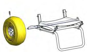
5.5.     Istruzione per la sostituzione delle parti ........................... 27
       5.5.1.        Assieme ruota ........................................................... 28
       5.5.2.        Telino seduta............................................................. 29
       5.5.3.        Telo poggiapiedi ....................................................... 30
       5.5.4.        Telo schienale ........................................................... 30
       5.5.5.        Kit clips di bloccaggio .............................................. 31
       5.5.6.        Barra antiribaltamento .............................................. 32
       5.5.7.        Struttura poggiagambe .............................................. 33
       5.5.8.        Supporto anteriore .................................................... 34
       5.5.9.        Tappo per estruso bracciolo ...................................... 34
       5.5.10.       Tubo schienale completo di telo ............................... 35
       5.5.11.       Assieme ruotino ........................................................ 36
6.     Condizioni di garanzia .............................................................. 37
     6.1.     Numero seriale.................................................................. 37
     6.2.     Incident reporting ............................................................. 37
1.     Product presentation ................................................................. 41
2.     Starting up ................................................................................ 42
     2.1.     Checks to be made on delivery ......................................... 42
     2.2.     Unpacking......................................................................... 42
     2.3.     Mounting the wheelchair .................................................. 43
     2.4.     Transport and storage ....................................................... 47
3.     Adjustments .............................................................................. 48
     3.1.     Legrest adjustment............................................................ 48
4.     Use of the wheelchair ............................................................... 49
     4.1.     Accessories ....................................................................... 50
       4.1.1.        Armrests ................................................................... 50
       4.1.2.        Third wheel kit.......................................................... 51
       4.1.3.        Sun awning ............................................................... 53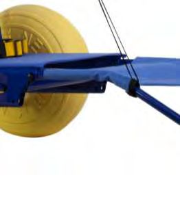
5.     Maintenance ............................................................................. 57
     5.1.     Maintenance and cleaning ................................................ 57
     5.2.     Controls to be performed on the wheelchair..................... 57
     5.3.     Tire puncture .................................................................... 58
     5.4.     Specifications ................................................................... 59
       5.4.1.        Dimensions ............................................................... 60
     5.5.     Instructions for parts replacement .................................... 61
       5.5.1.        Wheel assembly ........................................................ 62
       5.5.2.        Sling seat .................................................................. 63
       5.5.3.        Sling legrest .............................................................. 64
       5.5.4.        Sling backrest ........................................................... 64
       5.5.5.        Fasteners kit .............................................................. 65
       5.5.6.        Anti-tips bar .............................................................. 66
       5.5.7.        Legrest structure ....................................................... 67
       5.5.8.        Front support ............................................................ 68
       5.5.9.        Cap for extruded armrest .......................................... 68
       5.5.10.       Backrest tube including sling backrest ..................... 69
       5.5.11.       Third wheel assembly ............................................... 70
6.     Warranty terms ......................................................................... 71
     6.1.     Serial number.................................................................... 71
     6.2.     Incident reporting ............................................................. 71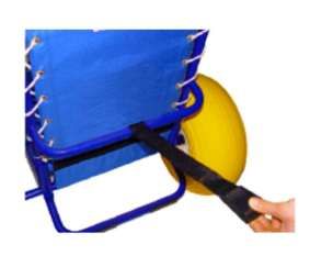

1. Presentazione della carrozzina
Caro Amico,
Ti ringraziamo per aver scelto un nostro prodotto.
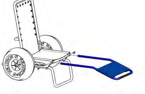
La JOB è una sedia per il trasporto di disabili ed anziani adatta al mare, alla neve
o al trekking off-road. È munita, infatti, di una coppia di ruote studiate per il
trasporto agevole su tutti i tipi di fondo (sabbia, ciottoli, neve).
Essendo costruita con materiali in lega di alluminio che non temono l’attacco della
salsedine, permette di entrare in acqua restando comodamente seduti.
È completamente smontabile per il trasporto anche in veicoli di piccole dimensioni.
Caratteristiche
• Ruote diametro 44 cm con pneumatici estraibili
• Smontabilità
• Ridotto ingombro del telaio smontato
• Telaio in alluminio
• Trattamento galvanico e verniciatura a polveri epossidiche
ATTENZIONE: È vietato l’utilizzo della carrozzina o di sue parti per scopi
diversi da quello indicato; per un corretto uso, si prega di attenersi alle
indicazioni riportate all’interno del presente manuale. La NEATECH.IT
declina ogni responsabilità da danni causati dall’uso improprio degli
ausili.
ATTENZIONE: Le informazioni contenute nel presente manuale
possono essere soggette a modifiche senza preavviso.
www.neatech.it
7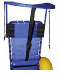
2. Messa in funzione
  2.1. Controlli da compiere all’atto della consegna
  •       Controllare l’integrità dell’imballo originale.
  •       Controllare eventuali anomalie sui documenti di trasporto.
  •       Controllare l’integrità e la funzionalità del dispositivo in tutte le sue parti
          al momento della consegna o subito dopo per assicurarsi che non vi siano
          danni dovuti al trasporto.
  •       Assicurarsi che la superficie del dispositivo non sia danneggiata o
          graffiata.
  2.2. Unpacking
All’interno dello scatolo ci sono:

      •    Schienale completo di telo
      •    Barra poggiagambe completa di telo
      •    Barra di appoggio anteriore
      •    Barra antiribaltamento
      •    Telaio principale completo di telo seduta e bloccaggi per tubo
      •    N. 2 Ruote pneumatiche
      •    N. 10 Clips di bloccaggio
      •    Documentazione
      •    Eventuali accessori acquistati

                                       SMALTIMENTO IMBALLAGGIO
                            Per riciclare correttamente i materiali di imballaggio della
                            Job seguire le indicazioni fornite dal servizio locale di
                            smaltimento rifiuti

                                    www.neatech.it
                                         8
2.3. Operazioni di montaggio
Barra antiribaltamento e barra di supporto
Inserire la barra antiribaltamento (D) e la barra di supporto anteriore (C) nel telaio
principale come evidenziato in Figura 1. Bloccare le due barre inserendo le clips di
bloccaggio.
Assicurarsi che i tubi risultino correttamente agganciati.
D
C
Figura 1
ATTENZIONE
I tubi (D) e (C) hanno uguale diametro ma (D) è più
lungo.
Se si invertono i tubi (D) e (C), la carrozzina risulta
sbilanciata con possibili pericoli per l’occupante.
www.neatech.it
9Ruote
Inserire la ruota destra e quella sinistra sull’asse del telaio come mostrato in Figura
2.
Utilizzare l’apposito foro di alloggiamento sul mozzo, preventivamente allineato
con il foro presente sull’asse del telaio e inserire a fondo la clip di bloccaggio (F).
Assicurarsi che le clips siano ben agganciati sui mozzi delle ruote.
F
Figura 2
Schienale
Inserire lo schienale nei tubi di supporto del telaio principale come mostrato in
Figura 3, quindi inserire negli appositi fori le due clips di bloccaggio per fissarlo.
Assicurarsi che i bloccaggi siano ben agganciati.
www.neatech.it
10Figura 3
Quindi fissare la fascia posta alla fine dello schienale passandola intorno all’asse
delle ruote così come mostrato in Figura 4.
Figura 4
ATTENZIONE
È necessario fissare accuratamente lo schienale con le
clips di fissaggio e stringere bene il velcro per evitare
un suo accidentale smontaggio.
www.neatech.it
11Barra poggiagambe
Inserire la barra poggiagambe negli appositi tubolari del telaio come evidenziato
in Figura 5 e bloccarla inserendo le due clips di bloccaggio (G). Per la regolazione
della barra poggiagambe vedere paragrafo 3.1.
G
G
Figura 5
ATTENZIONE
Assicurarsi che i tubi risultino correttamente agganciati.
Smontaggio della carrozzina
Per smontare la carrozzina eseguire all’inverso le operazioni descritte.
Assicurarsi che i bloccaggi di ruote e tubi rimangano incastrati nei rispettivi
alloggiamenti del telaio per evitarne la perdita.
www.neatech.it
122.4. Trasporto e immagazzinamento
Se non si intende usare la carrozzina per un lungo periodo, conservarla in un luogo
pulito.
Se è necessario trasportare la carrozzina Job, per facilitare le operazioni, è possibile
smontarla come descritto nel paragrafo 2.3 e riporla nell’apposita borsa fornita
come accessorio. Si consiglia di posizionare i pezzi della sedia come mostrato in
Figura 6
.
1018
553
505
Figura 6
www.neatech.it
133. Regolazioni
3.1. Regolazione poggiagambe
Per la regolazione del poggiagambe sganciare le due clips di bloccaggio come
mostrato in Figura 7.
Mettere il poggiagambe in una delle tre posizioni disponibili e inserire nuovamente
le due clips di bloccaggio.
Figura 7
www.neatech.it
144. Uso della carrozzina
Non utilizzare la carrozzina in acque profonde o agitate.
È necessaria la presenza di un accompagnatore quando la carrozzina è in acqua.
Per un uso in sicurezza dell’ausilio e per evitare situazioni di rischio per l’utente
verificare che la circonferenza delle ruote sia compresa tra 1380 e 1400 mm.
In caso contrario gonfiare o sgonfiare la ruota fino a rientrare nel range desiderato.
Figura 8
www.neatech.it
154.1. Accessori
La Job può essere equipaggiata con molteplici accessori che il produttore mette a
disposizione per soddisfare le diverse esigenze del cliente.
4.1.1. Coppia di braccioli
Montare i braccioli (dx e sx) allo schienale come mostrato in Figura 9. Per
assicurarsi un sicuro collegamento, avvitare correttamente le due viti in Figura 9
utilizzando un chiavino per bulloni ad esagono incassato da 6 mm.
Figura 9
www.neatech.it
164.1.2. Kit terza ruota
Non effettuare questa operazione con il paziente seduto
sulla sedia.
Per prima cosa smontare la barra poggiagambe e il tubolare di supporto anteriore
agendo semplicemente sulle clips di bloccaggio come evidenziato in Figura 10.
Figura 10
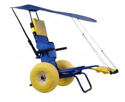
Quindi collegare il kit terza ruota infilando i tubolari nei fori posti nella parte
anteriore del telaio come mostrato in Figura 11.
Applicare dunque le clips di bloccaggio negli appositi fori per assicurare il corretto
collegamento.
L’eventuale regolazione in profondità è uguale alla regolazione fatta per la struttura
poggiagambe. Per maggiori informazioni vedere paragrafo 3.1.
www.neatech.it
17Figura 11
Prima di utilizzare il kit terza ruota controllare la
pressione del pneumatico.
La circonferenza della terza ruota deve essere
compresa fra 81 cm e 84 cm.
In caso contrario gonfiare o sgonfiare la ruota fino a che
la sua circonferenza rientra nel range indicato.
www.neatech.it
184.1.3. Tendalino parasole
La confezione del tendalino contiene:
• Borsello contenente il tendalino e le cinghie di aggancio (1)
• Supporti per il tendalino (2)
• Barre di sostegno del tendalino (3)
Figura 12
Dalle barre di supporto del tendalino rimuovere il copritubo nero individuando il
foro che non presenta linguette esterne (vedi Figura 13).
Figura 13
www.neatech.it
19Facendo riferimento alla Figura
14 inserire i supporti a testa
piatta di colore giallo nel foro
individuato; quindi inserire il
supporto per il tendalino
facendolo scorrere sullo
schienale. Mantenere i supporti a
testa piatta in posizione parallela
al terreno e rivolti verso l’alto.
Figura 14
Facendo riferimento alla Figura 15 agganciare la cinghia al tubolare sul retro dello
schienale in modo che il moschettone sia rivolto verso l’esterno.
Figura 15
www.neatech.it
20Agganciare la cinghia posta sul
retro del tendalino al
moschettone della cinghia
precedentemente fissata al
tubolare e tirare le cinghie fino a
che siano tese.
Figura 16
Agganciare i tiranti del tendalino ai tubolari del poggiagambe.
Figura 17
www.neatech.it
21Regolare la tensione dei tiranti agendo sui fermi a pressione fino a che il tendalino
è stabile rispetto alla sedia.
Figura 18
www.neatech.it
225. Manutenzione
Tutti gli interventi sulla carrozzina devono
essere effettuati da un centro assistenza
autorizzato
5.1. Manutenzione e pulizia
Una manutenzione regolare contribuisce a conservare intatte le funzionalità e la
sicurezza della Job. La carenza o l’insufficienza di cure e di manutenzione
comporta una limitazione della garanzia da parte del produttore.
Per la pulizia della sedia non utilizzare dispositivi a spruzzo d’acqua ad alta
pressione. Per le parti in plastica o metallo utilizzare un panno morbido inumidito
con detergenti non aggressivi. Per teli sedile, poggiagambe e schienale utilizzare
acqua tiepida e detersivo delicato.
Non utilizzare smacchiatori, solventi acidi ecc.
5.2. Controlli da effettuare sulla carrozzina
INTERVENTO PERIODICITÀ
Controllo Pressione ruote Settimanale
Per un uso in sicurezza la circonferenza
delle ruote nel range indicato ai
paragrafi 4 e 4.1.2.
Clips di bloccaggio Mensile
Controllare la presenza di tutte le clips
di bloccaggio.
Vedere paragrafo 5.5.5.
www.neatech.it
235.3. Foratura pneumatici
Nel caso di foratura della ruota, operare come indicato di seguito
• Pulire la zona danneggiata con alcool etilico.
• Quando la superficie è asciutta, applicare alcune gocce di sigillante per
PVC morbido.
• attendere alcuni minuti affinché la colla si secchi, quindi gonfiare la ruota
come descritto in questo manuale.
www.neatech.it
245.4. Specifiche tecniche
Massimo peso utente 125 kg
Peso a vuoto 7 Kg - Telaio
3 Kg – Ruota
Utilizzo previsto La Job è destinata a tutte quelle categorie di
utenti con difficoltà motorie temporanee o
permanenti che hanno l’esigenza di
compiere spostamenti sulla spiaggia e su
altri tipi di superfici impervie.
www.neatech.it
255.4.1. Dimensioni
465
420
710
360
795
900 1250
Le caratteristiche possono variare in base alla specifica
personalizzazione di ogni singola carrozzina.
www.neatech.it
265.5. Istruzione per la sostituzione delle parti
L’uso di parti di ricambio o accessori non approvati
dal produttore potrebbero rendere la carrozzina
instabile o incontrollabile.
Per ogni ordine contattare sempre un centro
assistenza autorizzato.
L’utente finale può comprare presso un centro assistenza autorizzato le parti di
ricambio e sostituirle in autonomia.
In caso di impossibilità a sostituire autonomamente le parti, rivolgersi ad un centro
assistenza autorizzato.
Codice Descrizione
R105-001 Assieme ruota
R105-002 Telino seduta
R105-003 Telo poggiapiedi
R105-004 Telo schienale
R105-005 Kit clips di bloccaggio
R105-006 Barra antiribaltamento
R105-007 Struttura poggiagambe
R105-008 Supporto anteriore
R105-009 Tappo per estruso bracciolo
R105-010 Tubo schienale completo di telo
R105-011 Assieme ruotino
R105-012 Tondino tubo seduto
www.neatech.it
275.5.1. Assieme ruota
Per la sostituzione dell’assieme ruota (dx o sx), togliere la clip (F) in Figura 19 e
sfilare la ruota. Inserire la nuova ruota sull’asse del telaio utilizzando l’apposito
foro di alloggiamento sul mozzo, preventivamente allineato con il foro presente
sull’asse del telaio e inserire a fondo la clip di bloccaggio (F).
Assicurarsi che la clip sia ben agganciata sul mozzo delle ruote.
F
Figura 19
Codice Descrizione
R105-001 Assieme ruota
www.neatech.it
285.5.2. Telino seduta
Per la rimozione del telo seduta, sfilarlo semplicemente come evidenziato in Figura
20. Inserire il nuovo telo negli appositi tubolari.
Figura 20
Laddove necessario è possibile sostituire anche il solo tondino tubo seduta
sfilandolo semplicemente dal telino.
Codice Descrizione
R105-002 Telino seduta
R105-012 Tondino tubo seduta
www.neatech.it
295.5.3. Telo poggiapiedi
Togliere il poggiagambe come descritto nel paragrafo 3.1 e sfilare il telo
poggiapiedi.
Inserire il nuovo telo nella stessa posizione, inserire il poggiagambe in una delle
tre posizioni disponibili e inserire nuovamente le due clips di bloccaggio negli
appositi fori.
Codice Descrizione
R105-003 Telo poggiapiedi
5.5.4. Telo schienale
Per la sostituzione del telo schienale sganciare la fascia posta nella parte posteriore
dello schienale e toglierla facendola passare intorno all’asse delle ruote.
Successivamente sfilare la corda, e infine togliere la fascetta che la mantiene
collegata ai tubolari.
Inserire il nuovo telo seguendo le indicazioni in verso contrario.
Codice Descrizione
R105-004 Telo schienale
www.neatech.it
305.5.5. Kit clips di bloccaggio
Laddove necessario è possibile sostituire le clips di serraggio, togliendo
semplicemente le vecchie e inserendo le nuove nella stessa posizione.
Figura 21
Le clips di serraggio come evidenziato in Figura 21 si trovano nelle posizioni di
seguito elencate:
N°2 Tubolare schienale
N°1 Ruota Job destra
N°1 Ruota Job sinistra
N°2 Supporto poggiagambe
N°2 Supporto anteriore
N°2 Barra antiribaltamento
Codice Descrizione
R105-005 Kit clips di bloccaggio
www.neatech.it
315.5.6. Barra antiribaltamento
Per la sostituzione della barra antiribaltamento, togliere le due clips di bloccaggio
e sfilare la barra come mostrato in Figura 22.
Inserire la nuova barra nella stessa posizione e assicurarsi di inserire correttamente
le clips di bloccaggio.
Figura 22
Codice Descrizione
R105-006 Barra antiribaltamento
www.neatech.it
325.5.7. Struttura poggiagambe
Per la sostituzione della struttura poggiagambe, togliere le due clips di bloccaggio
e sfilare la barra come mostrato in Figura 23.
Inserire la nuova barra nella stessa posizione e assicurarsi di inserire correttamente
le clips di bloccaggio.
Figura 23
Codice Descrizione
R105-007 Struttura poggiagambe
www.neatech.it
335.5.8. Supporto anteriore
Per la sostituzione del supporto anteriore, togliere le due clips di bloccaggio e
sfilare il supporto come mostrato in Figura 24.
Inserire la nuova barra nella stessa posizione e assicurarsi di inserire correttamente
le clips di bloccaggio.
Figura 24
Codice Descrizione
R105-008 Supporto anteriore
5.5.9. Tappo per estruso bracciolo
Per la sostituzione del tappo per estruso bracciolo (dx o sx), togliere il vecchio
tappo come evidenziato in Figura 25.
Inserire il nuovo nella stessa posizione applicando una leggera forza.
Figura 25
Codice Descrizione
R105-009 Tappo per estruso bracciolo
www.neatech.it
345.5.10. Tubo schienale completo di telo
Per la sostituzione del tubo schienale completo di telo, togliere le due clips di
bloccaggio e sfilare la barra come mostrato in Figura 26.
Inserire il nuovo schienale nella stessa posizione e assicurarsi di inserire
correttamente le clips di bloccaggio.
Figura 26
Codice Descrizione
R105-010 Tubo schienale completo di telo
www.neatech.it
355.5.11. Assieme ruotino
Per la sostituzione dell’assieme ruotino, svitare completamente le due viti (L)
indicate in Figura 27 utilizzando un chiavino per bulloni ad esagono incassato da
5 mm, allargare i due tubolari e sfilare la ruota.
Inserire la nuova ruota, agganciare i due tubolari e assicurarsi di stringere
correttamente le viti tolte in precedenza.
L
Figura 27
Codice Descrizione
R105-011 Assieme ruotino
www.neatech.it
366. Condizioni di garanzia
La JOB è un prodotto globalmente garantito per 24 mesi. La garanzia è valida per
difetti di materiale o di lavorazione. Sono escluse dalla garanzia le parti soggette
ad usura e le parti danneggiate da: eccessivo carico, utilizzo non corretto, modifiche
e riparazioni apportate da terzi non autorizzati dalla Neatech.it s.r.l.
La garanzia decade nel caso si riscontrino sul prodotto manomissioni, errato
immagazzinamento, manutenzione errata o non autorizzata.
6.1. Numero seriale
Per qualsiasi richiesta o assistenza comunicare il codice di identificazione che si
trova sulla parte anteriore del telaio di ogni Job, come mostrato in Figura 28.
Figura 28
6.2. Incident reporting
In caso di incidente in cui è coinvolta la sedia a rotelle contattare un centro
assistenza autorizzato. Per una lista di centri assistenza autorizzati contattare il
produttore:
Neatech.it
via A. de Curtis 4/A, 80040, Cercola (NA), Italia
www.neatech.it – info@neatech.it - +39 081 555 1946
www.neatech.it
37ENGLISH MANUAL
1. Product presentation
Dear Friend,
Thank You for choosing our product.
The JOB is a chair for the transport of elderly and disabled people adapted to the
sea, snow or off-road trekking. It is provided with a pair of wheels designed for an
easy transport on all type of surface (sand, pebbles, snow).
Because of the construction with aluminum alloy materials that don’t fear the attack
of the salt, with the Job you can enter the water staying comfortably seated.
It is completely demountable to facilitate the transport also in small vehicles.
Features
   •   44 cm diameter wheels with tires extractable
   •   Completely disassembling
   •   Reduced overall dimensions of the frame disassembled
   •   Aluminum frame
   •   Galvanic treatment and epoxy powder painting
  WARNING: It is prohibited to use the Wheelchair or its parts for any
  purpose other than that indicated; for a correct use please follow the
  instructions given in this manual. NEATECH.IT disclaims any
  responsibility for damages caused by improper use of aids.

  WARNING: The information contained in this manual may be subject to
  change and without prior notice.

                                 www.neatech.it
                                     41
2. Starting up
2.1. Checks to be made on delivery
• Check for the integrity of the original packaging.
• Check for any anomalies on the shipping documents.
• Check for the functionality and integrity of the device in all its parts, at the
time of delivery or immediately thereafter, to ensure that no damage has
resulted from a careless transport.
• Make sure the surface of the device is not damaged, scratched, bent, etc.
2.2. Unpacking
Inside the box there is:
• Backrest with upholstery
• Footrest with upholstery
• Front support
• Anti-tip bar
• Main frame with upholstery and tube fasteners
• N. 2 Pneumatic wheels
• N.2 wheel fasteners
• Documentation
• Purchased accessories
PACKAGING DIASPOSAL
To properly recycle the packaging materials follow the
instructions provided by your local waste disposal service.
www.neatech.it
422.3. Mounting the wheelchair
Anti-tip bar and front support bar
Insert anti-tip bar (D) and front support bar (C) into the main chassis (E) as shown
in Figure 29. Secure the two bars with fasteners.
Make sure tubes are correctly locked.
D
C
Figure 29
WARNING
Tubes (D) and (C) are of the same width but (D) is
longer.
If tubes (D) and (C) are inverted, the wheelchair will
result unbalanced with possible risk for the user.
www.neatech.it
43Wheels
Insert the wheel (lh and rh) on the axis of the chassis as shown in Figure 30.
Use the special housing hole on the hub, previously aligned with the hole present
on the axle of the frame and insert the fastener (F)
Make sure each wheel fastener is correctly locked on hub.
F
Figure 30
Backrest
Insert the backrest into the bushings on the main frame as shown in Figure 31, then
insert the 2 fasteners deeply through proper holes to lock it.
Make sure fasteners are correctly locked on main frame.
www.neatech.it
44Figure 31
After that fix strip located on bottom end of the backrest, passing it around wheels’
axle as shown in Figure 32.
Figure 32
WARNING
It is very important to carefully fix the backrest with
the fixing clips and the strip to avoid possible
dismounting
www.neatech.it
45Leg bar
Insert the legbar in the tubes of the chassis as shown in Figure 33 and lock it with
the 2 fasteners (G). For adjustment instructions see section 3.1
G
G
Figure 33
WARNING
Tighten correctly the two tubes.
Disassembly of the wheelchair
In order to disassemble the chair run the described operations in reverse.
Make sure that the looking of the wheels and tubes are trapped in their respective
housings of the frame to prevent loss.
www.neatech.it
462.4. Transport and storage
If you don’t want to use the Job for a long time, store it in a safe place
free from dust and moisture.
If you want to carry the wheelchair, in order to facilitate operations, it is possible
to disassemble it as described in section 2.3 and put it in the bag available as
accessory. It is recommended to put the pieces of the wheelchair as in Figure 34
1018
553
505
Figure 34
www.neatech.it
473. Adjustments
3.1. Legrest adjustment
To adjust the position of legrest, remove the fasteners as shown in Figure 35. Put
the legrest in one of the three available positions and insert again the fasteners.
Figure 35
www.neatech.it
484. Use of the wheelchair
Do not use wheelchair in deep or agitated water.
Presence of an assistant is obligatory when wheelchair is into the water.
For use in safety of the wheelchair and to avoid situations of risk for the user, verify
that the circumference of the wheels is between 1380 and 1400 mm.
If not inflate or deflate the wheel to within the recommended range.
Figure 36
www.neatech.it
494.1. Accessories
The Job can be equipped with many accessories that Neatech.it makes available to
meet different customer needs.
4.1.1. Armrests
Assemble the armrest (rh and lh) to the backrest as shown in Figure 37. To ensure
a proper connection tighten the two screws shown in Figure 37 with a 6 mm allen
wrench
1.
Figure 37
www.neatech.it
504.1.2. Third wheel kit
Please don’t make this operation while the user is
sitting on the wheelchair
First remove the leg bar and the front support bar simply acting on the fasteners as
shown in Figure 38.
Figure 38
So connect the third wheel kit inserting the tubes into the holes in front of the frame
as shown in Figure 39. Then apply the fasteners into the appropriate holes to ensure
proper connection.
The depth adjustment is the same adjustment as for the legbar. For more
information see section 3.1.
www.neatech.it
51Figure 39
Before using the third wheel kit, control that the pressure
of the tire is correct.
Make sure that the circumference of the wheel is
between 81 cm and 84 cm.
If not inflate or deflate the wheel until its circumference
is in the recommended range.
www.neatech.it
524.1.3. Sun awning
The awing package contains:
• Bag with awning and the straps for the coupling (1)
• Supports for the awing (2)
• Awning’s support bars (3)
Figure 40
From the support bars of the awnings remove the pipe cover black identifying the
hole that has no outer tabs (see Figure 41).
Figure 41
www.neatech.it
53Seeing Figure 42 insert the
yellow flat supports in the hole
just identified and then insert the
support for the awning by sliding
it on the backrest.
Keep the media flat-head upright
and facing up.
Figure 42
Seeing Figure 43 attach the strap to the tubular on the back of the backrest so that
the hook is facing towards the outside.
Figure 43
www.neatech.it
54Attach the strap on the back of
the awning to the hook of the
belt previously fixed to the tube
and pull the belts till they are
very stretched.
Figure 44
Attach the ties of the awning to the tubular of the legrest.
.
Figure 45
www.neatech.it
55Adjust the tension of the tie rods acting on cord lock till the awning is stable with
respect to the chair.
Figure 46
www.neatech.it
565. Maintenance
Any work on the wheelchair must be
performed by an authorized service center
5.1.Maintenance and cleaning
Regular maintenance helps to keep intact the functionality and safety of JOB.
Inadequate or lack of care and maintenance may cause a limitation of the warranty
from the manufacturer.
To clean the chair do not use high-pressure water spray devices. For plastic and
metal parts use a soft cloth dampened with mild detergent. For the upholstery,
linings, seat and back covers use warm water and mild detergent. Do not use stain
removers, solvents, acids, etc.
5.2. Controls to be performed on the wheelchair
OPERATION FREQUENCY
Tire pressure Weekly
For a safe use of the wheelchair check
that the circumference of wheels is in
the range specified in section 4 and
4.1.2.
Fasteners Monthly
Check for the presence of all fasteners.
See section 5.5.5.
www.neatech.it
575.3. Tire puncture
In case of tire puncture please follow these instructions.
• Clean damaged surface with ethylic alcohol.
• When surface is dry; apply few drops of a glue for rigid PVC.
• Wait some minutes to let glue dry, then inflate wheels as described in this
manual.
www.neatech.it
585.4. Specifications
Maximum user weight 125 kg
Empty weight 7 Kg – Chassis
3 Kg – Wheel
Intended use Job is intended to all those categories of
users with temporary or permanent
mobility difficulties who need to make trips
to the beach and other types of impervious
surfaces.
www.neatech.it
595.4.1. Dimensions
465
420
710
360
795
900 1250
Specifications may change according to the
customization of each wheelchair.
www.neatech.it
605.5. Instructions for parts replacement
The use of spare parts or accessories not approved
by the manufacturer may make the wheelchair
unstable or uncontrollable.
For each order, always contact an authorized service
center.
The final user can buy spare parts at an authorized service centers and substitute
by himself.
If the user is not able to substitute himself any parts, he can contact an authorized
service center.
Code Description
R105-001 Wheel assembly
R105-002 Sling seat
R105-003 Sling legrest
R105-004 Sling backrest
R105-005 Fasteners kit
R105-006 Anti-tips bar
R105-007 Legbar structure
R105-008 Front support
R105-009 Cap for extruded armrest
R105-010 Backrest tube including sling backrest
R105-011 Third wheel assembly
R105-012 Axis of the sling seat
www.neatech.it
615.5.1. Wheel assembly
To substitute the wheel assembly (rh or lh) remove the fastener (F) in Figure 47
and remove the wheel.
Insert the new wheel on the axis of the frame using the appropriate location hole,
previously aligned with the present hole on the axis of the frame and fully insert
the locking clip (F).
Make sure that the fastener is securely attached to the hub of the wheels.
F
Figure 47
Code Description
R105-001 Wheel assembly
www.neatech.it
625.5.2. Sling seat
To remove the sling seat, simply pull out as shown in Figure 48. Enter the new seat
in the appropriate tube.
Figure 48
If necessary it is possible to replace only the rod axis simply by pulling it out of the
sling seat.
Code Description
R105-002 Sling seat
R105-012 Axis of the sling seat
www.neatech.it
635.5.3. Sling legrest
Remove the legrest ad described in section 3.1 and remove the sling legrest.
Insert the new sling legrest in the same position, insert the legrest in one of the
three available positions and insert again the two fasteners in the appropriate holes.
Code Description
R105-003 Sling legrest
5.5.4. Sling backrest
To replace the sling backrest release the strip on the rear part of the backrest and
remove it by passing it around the axis of the wheels.
After that remove the rope, and then remove the ties that keeps it attached to the
tubes.
As described enter the new sling backrest in the opposite direction.
Code Description
R105-004 Sling backrest
www.neatech.it
645.5.5. Fasteners kit
If necessary you can replace the fasteners simply removing the old ones and
entering the new in the same position.
Figure 49
The fasteners as shown in Figure 49 are located in the positions listed below:
N°2 Backrest tube
N°1 Right wheel
N°1 Left wheel
N°2 Legrest support
N°2 Front support
N°2 Anti-tips bar
Code Description
R105-005 Kit of fasteners
www.neatech.it
655.5.6. Anti-tips bar
To change the anti-tip bar, remove the two fasteners and pull the bar as shown in
Figure 50.
Insert the new bar in the same position, and be sure to properly insert the fasteners.
Figure 50
Code Description
R105-006 Antip-tips bar
www.neatech.it
665.5.7. Legrest structure
To substitute the footrest structure remove the two fasteners and pull the bar as
shown in Figure 51.
Insert the new bar in the same position, and be sure to properly insert the fasteners.
Figure 51
Code Description
R105-007 Legrest structure
www.neatech.it
675.5.8. Front support
To replace the front support, remove the two fasteners and remove the bar as shown
in Figure 52.
Insert the new bar in the same position, and be sure to properly insert the fasteners.
Figure 52
Code Description
R105-008 Front support
5.5.9. Cap for extruded armrest
To substitute the cap for extruded armrest (rh and lh), remove the old cap as shown
in Figure 53.
Insert the new one in the same position applying a light pressure.
Figure 53
Code Description
R105-009 Cap for extruded armrest
www.neatech.it
685.5.10. Backrest tube including sling backrest
To substitute the backrest tube comprehensive of sling backrest, remove the two
fasteners and pull the bar as shown in Figure 54.
Insert the new backrest in the same position and be sure to properly insert the
fasteners.
Figure 54
Code Description
R105-010 Backrest tube including sling backrest
www.neatech.it
695.5.11. Third wheel assembly
To replace the third wheel assembly, unscrew the two bolts (L) shown in Figure 55
using a 5 mm allen wrench, expand the two tubes and remove the wheel.
Insert the new wheel, hook the two tubes and make sure to properly tighten the
bolts previously removed.
L
Figure 55
Code Description
R105-011 Third wheel assembly
www.neatech.it
706. Warranty terms
JOB is a product globally guaranteed for 24 months. The warranty covers defects
in materials or workmanship. The warranty doesn’t cover parts subject to usury or
damaged parts by: overload, misuse, alterations and repairs made by unauthorized
third parties from Neatech.it s.r.l. .
The warranty expires in case of tampering, improper storage, unauthorized or
incorrect maintenance.
6.1. Serial number
For any report or assistance request communicate the unique identification code on
the chassis of each JOB as shown in Figure 56.
Figure 56
6.2. Incident reporting
If an incident occurs please contact an authorized service center. For a list of
authorized service center please contact the manufacturer:
Neatech.it srl
4/A, A. de Curtis st.- 80040, Cercola (NA), Italy
www.neatech.it – info@neatech.it - +39 081 555 1946
www.neatech.it
71www.neatech.it
72Neatech.it s.r.l.
via A. De Curtis, 4/A - 80040 Cercola (NA) Italy
tel. +39 0815551946 - fax +39 0815552507
www.neatech.it - info@neatech.itPuoi anche leggere