OPERATING INSTRUCTIONS MANUALE D' ISTRUZIONE - AUTOMATIC SCREW FEEDER ALIMENTATORE AUTOMATICO DI VITI
←
→
Trascrizione del contenuto della pagina
Se il tuo browser non visualizza correttamente la pagina, ti preghiamo di leggere il contenuto della pagina quaggiù
AUTOMATIC SCREW FEEDER

ALIMENTATORE AUTOMATICO DI VITI

       OPERATING INSTRUCTIONS
        MANUALE D’ ISTRUZIONE

               Via Marco Corner, 19/21
             36016 THIENE (VI) ITALIA
                Tel. +39 0445 371068
                Fax +39 0445 371069
                   kolver@kolver.it
                    www.kolver.it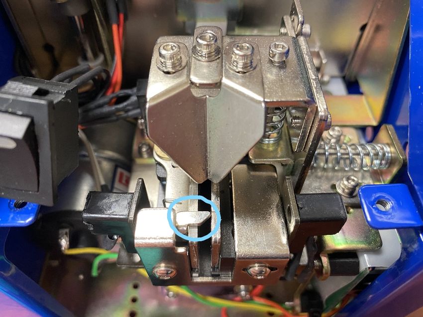
CONTENTS
INDICE

Features ….……..………………………………………………………………………………… 3
Caratteristiche

General instructions …………………………………………………………………………….… 4
Indicazioni generali

Mechanical description…..………………………………………………………………………… 7
Descrizione meccanica

Technical data ……………………………………...……………………………………………… 8
Dati tecnici

Adjustments………………………………………………………………………………………… 8
Regolazioni

Troubleshooting…………………………………………………………………………………… 15
Risoluzione dei problemi

Exploded view & spare list……………………………………………………………………...….17
Esploso & lista ricambi

Declaration of conformity…………………………………………………………………………..20
Dichiarazione di conformità

Vers. 280421                                              2
Features                                        Caratteristiche

Adjustable for a wide range.                      Ampio range di regolazione.

This automatic screw feeder can handle wide       Questo alimentatore automatico di viti serie
range of screws, e.g. metric or self-tapping      NFK può supportare diversi tipi di viti, p. es.
screws, between M1 and M5 and 20 mm max           metriche o autofilettanti, in un range di
length.                                           diametro da M1 a M5 con una lunghezza
                                                  massima di 20 mm.

Working smoothly                                  Lavoro continuo senza inceppamenti.
The NFK can work continuously without             Grazie al particolare circuito di carica e al
interruptions or jams thanks to the particular    movimento della spazzola, l’NFK può
loading circuit and to the movement of the        lavorare in modo continuo senza interruzioni
brush. Any screw in the wrong position falls in   o inceppamenti. Inoltre, grazie alla spazzola,
the screw storage so the loading cycle can        le viti in errata posizione vengono fatte
restart.                                          scivolare nel serbatoio ricominciando così il
                                                  ciclo di carica.

Adjustable speed
                                                  Velocità regolabile.
It’s possible to adjust the vibration speed and
                                                   Grazie a due potenziometri, è possibile
the speed of the brush / loading wheel.
                                                  regolare sia la velocità di scorrimento viti
Different combinations of speed allow to
                                                  (vibrazione) che la velocità della
adapt the NFK to different works.
                                                  spazzola/ruota di carica. Le varie
                                                  combinazioni di velocità permettono così di
                                                  adattare l’NFK a diversi tipi di lavoro.

    Vers. 280421                                                                             3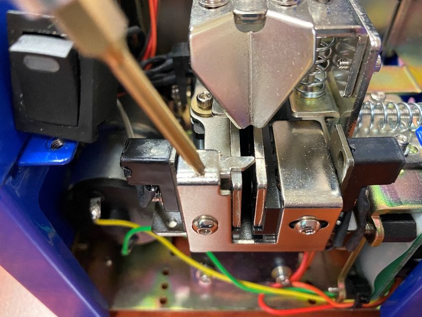
General instructions                             Indicazioni generali

Before performing any such task, please read       Prima di qualsiasi utilizzo, leggere
carefully these instructions and save them for     attentamente e conservare queste istruzioni.
future reference.

NFK Accessories.                                   Accessori NFK.
                                                   All’interno della confezione sono presenti i
The NFK package contains:                          seguenti accessori:
- 1 x NFK already adjusted at the size             - 1 x NFK già tarato nella misura richiesta
required                                           - 1 x Manuale istruzioni
- 1 x Instruction manual                           - 1 x Alimentatore AC/DC
- 1 x AC/DC adapter + power cord                   - 1 x kit di spessori per le differenti regolazioni
- 1 x kit of spacers                               - 1 x Chiave esagonale
- 1 x hexagonal key

General precautions.                               Precauzioni per l’installazione.

Install the NFK in a stable horizontal position:   Sistemare l’NFK in posizione stabile e
an inclined base can affect the correct output     orizzontale, una base inclinata può influire
of the screws. Improper installation could         sulla corretta uscita delle viti. Una posizione
cause the NKF to fall or jam.                      non adeguata può provocare la caduta o
                                                   l’inceppamento della macchina.

Workplace.                                         Ambiente operativo.
                                                   Non posizionare l’NFK in un luogo in cui
Do not operate in presence of oil smoke,
                                                   siano presenti esalazioni d’olio, vapori,
steam, moisture or dusts. It may occur fire or
                                                   umidità o grandi quantità di polvere,
electric shock.
                                                   potrebbero verificarsi incendi o scosse
                                                   elettriche.

    Vers. 280421                                                                                4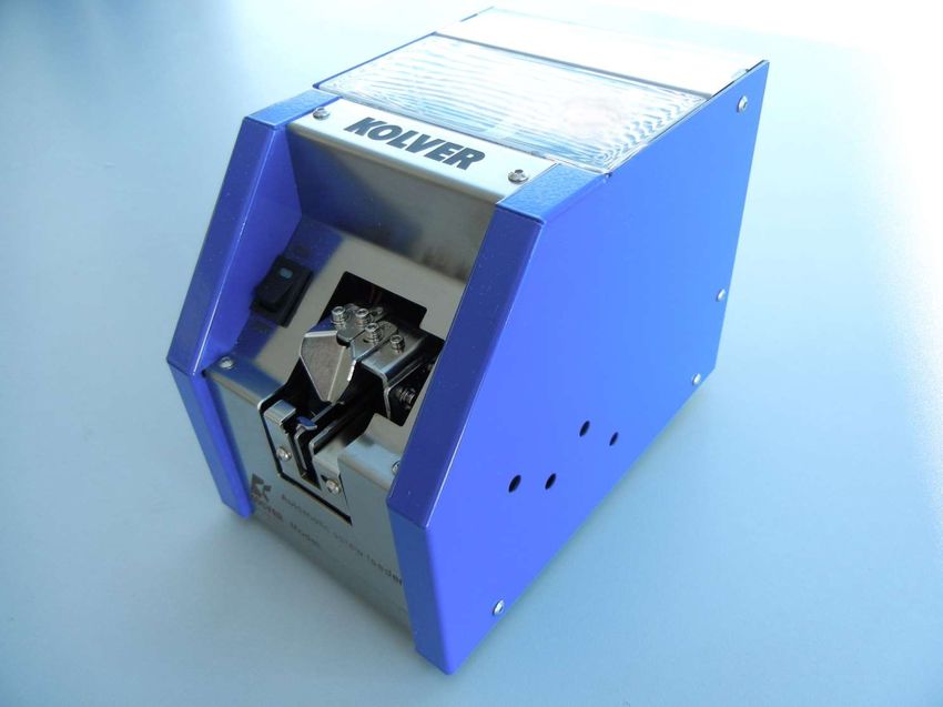
General instructions                             Indicazioni generali

Cleaning.                                          Pulizia.

Keep clean the lubricated parts and check          Mantenere pulite le parti lubrificate,
them periodically.                                 controllandole periodicamente.

Keep the screw storage clean and be careful        Mantenere pulito il serbatoio viti e fare
of possible foreign material inside. Regularly     attenzione all’eventuale caduta di materiale
inspect the rail.                                  estraneo al suo interno. Controllare
                                                   periodicamente anche la corsia.

AC/DC Adapter.                                     Alimentatore AC/DC.
Do not use any AC/DC adapter other than the        Utilizzare solo l’alimentatore in dotazione.
specific one. It may occur fire or electric        L’uso di altri alimentatori può provocare
shock.                                             incendi o scosse elettriche.

Rail.                                              Corsia.
                                                   Maneggiare la corsia con cura: non ha
Handle the rail carefully. It does not need to     bisogno di essere lubrificata, ma pulita
be lubricated but cleaned periodically. The dirt   periodicamente, se sporca può bloccare il
can block the screw flowing.                       passaggio delle viti.

                                                   Estrazione viti.
Picking up the screws.
                                                   Per prelevare la vite è sufficiente una minima
Do not exert any force to pick up the screw.       pressione. Dare una forza eccessiva o colpire
Excessive force could break or hit the unit.       la macchina può provocarne la rottura.

    Vers. 280421                                                                              5
General instructions                           Indicazioni generali

Screw.                                            Viti.
                                                  Non utilizzare viti sporche o unte d’olio, lo
Do not use dirty or greasy screws, all dirt can   sporco può inceppare l’NFK. Scegliere solo
clog the NFK. Use only suitable screws (see       viti delle dimensioni indicate (vedere Dati
Technical Data). Do not overfill the storage,     Tecnici).
the correct amount is described here below.       Non riempire troppo il serbatoio, la quantità
                                                  corretta è indicata nella figura sottostante.

Covers.                                           Cover.
Before any performace, make sure that all the     Prima dell’utilizzo, assicurarsi che tutte le
covers are closed and secure.                     cover siano chiuse e ben fissate.

IMPORTANT: Switch off the NFK before              IMPORTANTE: Spegnere l’apparecchio prima
opening the covers.                               di aprire le cover.

When the NFK is off.                              Quando l’NFK è spento.
Disconnect the AC/DC adapter, when the unit       Se l’NFK non viene utilizzato per un tempo
is not used for an extended period of time.       prolungato, è consigliabile spegnerlo e
                                                  scollegare l’alimentatore AC/DC.
WARNING. When an abnormality occurs,
stop immediately, turn off the power and          ATTENZIONE. Interrompere immediatamente
unplug the power cord of the unit. Contact        l’utilizzo e scollegare l’alimentatore, se si
your Kolver dealer immediately.                   dovessero avvertire malfunzionamenti o
                                                  anomalie, contattare subito un centro
                                                  assistenza Kolver.

    Vers. 280421                                                                              6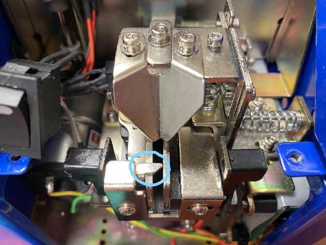
dei problemi. description
 Mechanical                 Descrizione meccanica

                            Descrizione meccanica

Descrizione meccanica

   Vers. 280421                                     7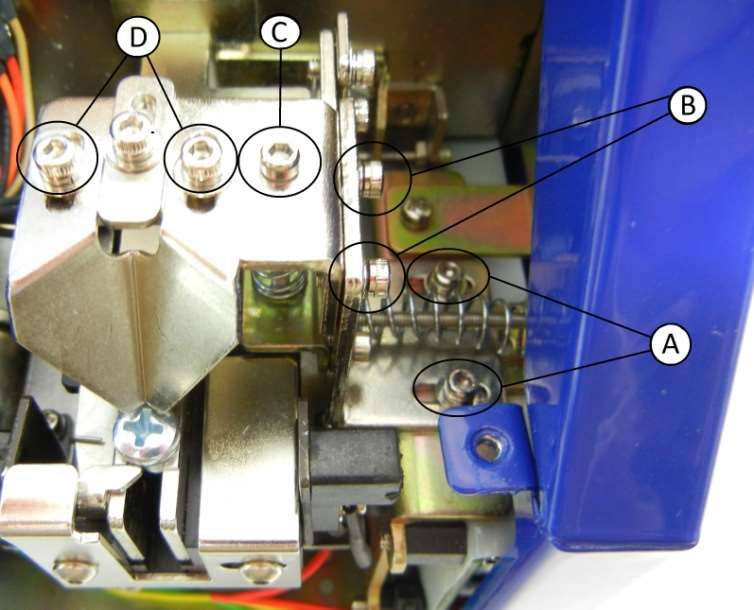
Technical data                              Dati tecnici

Screw: Suitable for every head shape         Viti: Adatto ad ogni tipo di testa

    D: Head diameter                        D: Diametro testa
    A: Shank length                         A: Lunghezza gambo

    L: Total lenght                         L: Lunghezza totale vite

                                            Tensione di alimentazione: 12V DC 500mA
Voltage: 12V DC 500mA
                                            Alimentatore: tensione IN 100/240 AC
Tension: IN 100/240 AC
                                                                   OUT 12V DC 1,25A
OUT 12V DC 1,25A
                                            Dimensioni: 184 x 123 x 148 mm (L*W*H)
Dimensions: 184 x 123 x 148 mm (L*W*H)
                                            Peso: 2,75 Kg
Weight: 2,75 Kg
                                            Temperatura operativa: 0°C a +50°C
Storage temperature: from 0°C to +50°C
                                            IMPORTANTE: Lo strumento non ha la
IMPORTANT: the item is not grounded!
                                            messa a terra! Nel caso fosse necessario, va
In case it’s necessary, please connect an   connessa un occhiello ad una vite posta nel
eylet to a screw on the bottom.             fondo.

   Vers. 280421                                                                    8
Adjustments                                     Regolazioni

Brush adjustment.                                 Regolazione della spazzola.

The eject brush places the screws that flows      La spazzola posiziona correttamente le viti
along the track and throws the ones in the        che procedono lungo la corsia e sposta nel
wrong position in the storage.                    serbatoio quelle in posizione errata.

Procedure:                                        Procedura:

To adjust the eject brush height, loosen the      Per regolare l’altezza della spazzola:
screws in the picture below, raise or lower the   allentare le viti evidenziate nella foto, alzare o
brush to the height of the head of your screw.    abbassare la spazzola in base all’altezza
                                                  della testa della vite utilizzata.

                                                  Se la spazzola viene regolata troppo alta,
If the brush has been set too high, screws in     alcune viti in posizione non corretta
the wrong position could pass and stop the        potrebbero passare ed ostruire il passaggio.
passage. If too low, the brush could get stuck.   Se invece viene regolata troppo bassa
                                                  potrebbe sbattere sulla corsia bloccandosi.

    Vers. 280421                                                                              9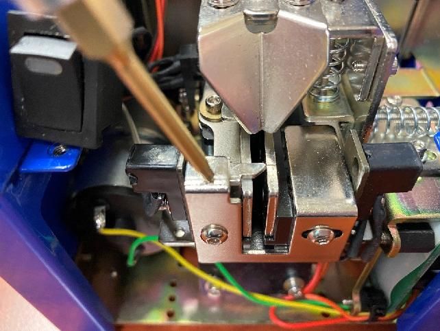
Adjustments                                       Regolazioni

Bit guide & track cover adjustment.               Regolazione guida inserto e copri corsia.

To pick the screw up correctly, the bit guide     Per prelevare la vite correttamente, la guida
should be centered on the screw head (see         inserto va centrata sulla testa della vite
picture below). It’s also possible to adjust it   stessa (come da figura). La guida inserto può
right/left and forward/backward. It should be     anche essere regolata destra/sinistra e
also adjusted the height of the track cover in    avanti/indietro. Va regolata anche l’altezza del
such a way as to pass only the screws in the      copri corsia in modo tale da far passare solo
correct position.                                 le viti in posizione corretta.

Procedure:                                        Procedura:
Remove the front panel by unscrewing the 4        Togliere la cover frontale svitando le 4 viti
screws as in the picture below and by slipping    come in figura e sfilando il tasto di
off the power button.                             accensione.

                     +

    Vers. 280421                                                                             10
Adjustments Regolazioni
To adjust the bit guide right/left, loosen A Per la regolazione destra/sinistra allentare le
screws and turn E screw: clockwise to move viti A e agire sulla vite E: in senso orario per
the bit guide to the right, and spostare il guida inserto verso destra, ed in
counterclockwise to move it to the left. Once senso antiorario per spostarlo verso sinistra.
you have found the right spot, tighten A Dopo aver trovato il punto corretto fissare le
screws. viti A.
To move it forward/backward, loosen D Per muovere in avanti/indietro la guida
screws, find the correct position and fasten it inserto allentare le viti D, trovarne la corretta
again. posizione e fissarle nuovamente.
Per regolare l’altezza del blocco copri corsia-
To adjust the height of the block track cover-
guida inserto allentare le viti B, ed agire sulla
bit guide, loosen B and C screws and turn the
vite C, in senso orario per abbassarlo, ed in
screw clockwise to lower, and
senso antiorario per alzarlo. Dopo aver
counterclockwise to raise it. Once you have
trovato il punto corretto fissare le viti B.
found the right spot tighten B screws.
E’ possibile regolare anche l’avanzamento del
To adjust the advancement of the track cover
copri corsia, tramite le viti F fino a coprire la
using F screws to cover up to the penultimate
penultima vite (vedi figura sinistra).
screw (see picture here below).
Vers. 280421 11Adjustments Regolazioni
Speed adjustment. Regolazione velocità.
To adjust the vibration speed and the speed E’ possibile regolare la velocità d’uscita delle
of movement of the brush/ loading wheel viti (vibrazione) e la velocità di movimento
depends on the use and on the type of screw. della spazzola/ruota di carico in base al tipo
di vite e di utilizzo.
G trimmer adjusts the vibration speed, while
H trimmer adjusts simultaneously the speed Il trimmer G regola la velocità d’uscita,
of the brush and of the wheel of charge. For mentre il trimmer H regola
both the trimmer, if turned clockwise, the contemporaneamente la velocità della
speed increases, anticlockwise it decreases. spazzola e la velocità della ruota di carico.
Per entrambi i trimmer, se ruotati in senso
orario la velocità aumenta, in senso antiorario
diminuisce.
After the adjustments, reassemble the NFK. Dopo aver eseguito la regolazione,
Make sure that all screws are tightened riassemblare l’NFK.
properly. Assicurarsi che tutte le viti siano serrate
correttamente.
Vers. 280421 12Adjustments Regolazioni
Track adjustment. Regolazione corsia.
Thanks to the kit of spacers (from 1.3 to 5.3 Grazie al kit di distanziali, con spessore da
mm of thickness ) supplied with the NFK, it is 1.3 a 5.3 mm, è possibile tarare l’NFK per viti
possible to adjust the NFK screws from M1 to da M1 a M5.
M5.
Procedure. Procedura.
Remove the front panel as previously Togliere la cover frontale come
explained (see Bit guide regulation). precedentemente illustrato (vedi Regolazione
della guida inserto).
To remove the track, it’s first necessary to
enlarge the 2 gate lock screws. Loosen the i Per estrarre la corsia, prima è necessario
and L screws, then M and N screws up to a allargare i 2 gate blocca viti. Allentare i fermi
sufficient width to extract the track. tramite le viti i ed L, successivamente le viti
M ed N fino ad una larghezza
sufficientemente adeguata ad estrarre la
corsia.
Vers. 280421 13Adjustments Regolazioni
Loosen O screw and then extract the track. Allentare la vite O e quindi estrarre la corsia.
After removing the track and choosing the 2 Dopo avere estratto la corsia ed aver scelto i
spacers suitable to the screw used, loosen P 2 distanziali adatti per la vite utilizzata,
and Q screws, and unscrew R screw. allentare le viti P e Q e svitare
completamente la vite R.
Replace the spacer and tighten the screw R Sostituire il distanziale, inserire quello dello
staring the new one at an angle of about 30 °. spessore desiderato ad un angolo G di circa
At the same time enter the second spacer at 30° e riavvitare la vite R.
end of the track as a reference for the Contemporaneamente inserire il secondo
distance between the two plates, then tighten distanziale all’uscita della corsia, come
P and Q screws. riferimento per la distanza tra le due piastre,
quindi fissare le viti P e Q.
Vers. 280421 14Adjustments Regolazioni
Reassemble the track, tighten O screw and Riassemblare la corsia, fissare la vite O e
closed the gates through M and N screws, chiudere i 2 gate tramite le viti M e N
clearance of 1 mm. Tighten i and L screw. mantenendo circa 1 mm di distanza dalla
corsia. Fissare i fermi tramite le viti i e L.
Adjust the bit guide and the cover track
Each new shape screw
È necessario regolare nuovamente il
guida inserto ed il copri corsia ad ogni
cambio di vite.
Vers. 280421 15Troubleshooting. Risoluzione dei problemi.
ERRORE CAUSA SOLUZIONE
L’NFK non si accende L’alimentatore AC/DC non Collegare l’alimentatore
è collegato all’NFK e alla presa di
corrente
Il tasto di accensione è in Premere ON nel tasto di
posizione OFF accensione
L’NFK è acceso ma le viti Viti con specifiche errate Verificarne le dimensioni
non escono e tarare correttamente
l’NFK
Copri corsia regolato Controllarne la taratura
troppo basso del copri corsia
Velocità di uscita troppo Aumentare la velocità
bassa
Materiale esterno caduto Pulire serbatoio e corsia
nel serbatoio
Viti bloccate nella corsia Spazzola, corsia, copri Tararli nuovamente
corsia in posizione errata
PROBLEM CAUSE COUNTERMEASURES
NFK does not turn ON The AC/DC adapter is not Connect the AC/DC
connected to the power adapter to the power
source source
The power switch is set Set on ON the power
on OFF switch
NFK is set on ON but Screws not suitable Check the screw size and
screws don’t exit properly calibrate the
NFK
Track cover adjusted too Adjust the track cover
low again
Exit speed too low Increase the speed
Foreign material inside Clean the storage and the
the storage track
Screws stuck in the track Brush, track, cover track Adjust them again
in wrong position
Vers. 280421 16Exploded view & spare list. Esploso & lista ricambi.
CODICE/
RIF. DESCRIPTION
CODE
K101 NFK-K101 Front panel
K102 NFK-K102 Back panel
K103 NFK-K103 Rim board-left
K104 NFK-K104 Rim board-right
K105 NFK-K105 Front board
K106 NFK-K106 Base plate
K107 NFK-K107 Eccentric pulley fix board
K109 NFK-K109 Rear board
K110 NFK-K110 Mini motor fix board D
K111 NFK-K111 Wipe units
K112 NFK-K112 Mini motor fix steel board-rim (4)
K113 NFK-K113 Mini motor fix board
K114 NFK-K114 Track board-down
K115 NFK-K115 Sensor fix base-1
K116 NFK-K116 Sensor fix base
K117 NFK-K117 Track base guide board
K118 NFK-K118 Sensor fix base-2
K119 NFK-K119 Track baseK120 NFK-K120 Block board-front K121 NFK-K121 M/C fix board K122 NFK-K122 Track connectiong board-1 K123 NFK-K123 Track board-front (2) K124 NFK-K124 Track connectiong board-1 K125 NFK-K125 Track board-right K126 NFK-K126 Track board-left K127 NFK-K127 Block board connectiong board K128 NFK-K128 Spring fix board K129 NFK-K129 Bit guide fix board K130 NFK-K130 Bit guide fix upper board K131 NFK-K131 Block board K132 NFK-K132 Sensor fix base-5 K133 NFK-K133 Sleeve fix board-1 K134 NFK-K134 Adjust board K135 NFK-K135 Adjust board K136 NFK-K136 Mini motor fix board-1 K137 NFK-K137 45 teeth-M1 K138 NFK-K138 Bit guide K139 NFK-K139 Rocking fix board K201 NFK-K201 Spin spindle K202 NFK-K202 Rocking main spindle K203 NFK-K203 Stud-4 K204 NFK-K204 Eccentric pulley K205 NFK-K205 Rocking main spindle K301 NFK-K301 20 teeth-M1 K302 NFK-K302 Bush-1006 K303 NFK-K303 Roller K304 NFK-K304 Inside fix board K305 NFK-K305 Inner board K306 NFK-K306 Eccentric pulley-3 K307 NFK-K307 Washer (2) K308 NFK-K308 Sleeve K309 NFK-K309 Bush-0606 (2) K310 NFK-K310 Stud (2) K311 NFK-K311 Stud K312 NFK-K312 Outer board-right-manual K313 NFK-K313 Sheave-1 K314 NFK-K314 Kit of Spacers (18) K315 NFK-K315 M/C fix board rod K316 NFK-K316 Sensor-1 (2) K317 NFK-K317 11 teeth-M1 K318 NFK-K318 Wipe units K319 NFK-K319 Outer board-up K320 NFK-K320 Load board K321 NFK-K321 Outer board-left-manual Vers. 280421 18
K401   NFK-K401   Start button
       NFK-K402   Power supply
K403   NFK-K403   Power socket

K404   NFK-K404   Sensor
K405   NFK-K405   Mini-motor A (reducer)
K406   NFK-K406   Sensor
K407   NFK-K407   Mini-motor B
K408   NFK-K408   Cushion-8 (2)
K409   NFK-K409   Cushion-6 (2)

K411   NFK-K411   Spring (0,8-1,0x28L)
K412   NFK-K412   Torque spring (Ø0,5&0,6xØ8)
K416   NFK-K416   Main board

S01    NFK-S01    Cross round head+spring washer+washer (16)   M2,6x0,45Px4,5L
S02    NFK-S02    Cross pan head+spring washer (13)            M3x0,5Px6L
S03    NFK-S03    Cross pan head (6)                           M3x0,5Px6L
S04    NFK-S04    Cross flat head (4)                          M3x0,5Px8L
S05    NFK-S05    Cross pan head+spring washer+washer (63)     M2,6x0,45Px4,5L
S06    NFK-S06    Cross pan head+spring washer+washer (4)      M2,6x0,45Px10L
S07    NFK-S07    Cross pan head+spring washer+washer (2)      M2,6x0,45Px12L
S08    NFK-S08    Cross pan head+spring washer+washer (12)     M2,6x0,45Px6L
S09    NFK-S09    Cross pan head+spring washer (2)             M3x0,5Px15L
S10    NFK-S10    Cross flat head (6)                          M2,6x0,45Px8L
S11    NFK-S11    Hex socket+spring washer+washer (10)         M2,6x0,45Px5,5L
S12    NFK-S12    Hex socket+spring washer+washer (2)          M2,6x0,45Px8L
S13    NFK-S13    Hex socket                                   M2,6x0,45Px20L
S14    NFK-S14    Hex socket                                   M2,6x0,45Px28L
S15    NFK-S15    Hex socket                                   M2,6x0,45Px38L
S16    NFK-S16    Cross flat head (3)                          M3x0,5Px5L
S17    NFK-S17    Hex nut (2)                                  M2,6x0,45P
S18    NFK-S18    E type knob                                  ext. Ø6
S19    NFK-S19    Hex socket conicity                          M3x0,5Px4L
S20    NFK-S20    E type knob                                  ext. Ø3
S21    NFK-S21    Hex socket (2)                               M2,6x0,45Px20L
S22    NFK-S22    Washer (4)                                   3x8

  Vers. 280421                                                                   19
DICHIARAZIONE DI CONFORMITA’/
DECLARATION OF CONFORMITY
KOLVER S.r.l.
VIA MARCO CORNER, 19/21
36016 THIENE (VI) ITALIA
Dichiara che la macchina nuova qui descritta/ Declare that the new tool here described:
Alimentatore automatico di viti/ Automatic screw feeder:
NFK N14 014514
NFK N17 014517
NFK N23 014523
NFK N26 014526
NFK N30 014530
NFK N40 014540
NFK N50 014550
È conforme alle disposizioni legislative che traspongono le direttive/ Is in conformity with the following standards and
other normative documents: 2006/42/CE, LVD 2014/35/UE, EMCD 2014/30/UE, EN 62841-2-2:2014,
EN 62841-1: 2015, EN 60204-1, EN 61000-6-2, EN 61000-6-4.
È conforme alla direttiva RoHS III (2011/65/UE e successiva 2015/863)/
It is also in conformity with RoHS III normative (2011/65/UE and following 2015/863).
Nome/Name: Giovanni Colasante
Posizione/Position: Amministratore Delegato/General Manager
Persona incaricata a costituire il fascicolo tecnico presso la Sede/
Person authorized to compile the technical file in Kolver
Thiene, 1° gennaio 2021 Giovanni Colasante
Vers. 280421 20AUTOMATIC SCREW FEEDER /RS
ALIMENTATORE AUTOMATICO DI VITI /RS
OPERATING INSTRUCTIONS
MANUALE D’ ISTRUZIONE
Via Marco Corner, 19/21
36016 THIENE (VI) ITALIA
Tel. +39 0445 371068
Fax +39 0445 371069
kolver@kolver.it
www.kolver.itCONTENTS INDICE Features ….……..………………………………………………………………………………… 3 Caratteristiche General instructions …………………………………………………………………………….… 4 Indicazioni generali Mechanical description…..………………………………………………………………………… 7 Descrizione meccanica Technical data ……………………………………...……………………………………………… 8 Dati tecnici Adjustments………………………………………………………………………………………… 8 Regolazioni Options………..…………………………………………………………………………………… 15 Opzioni Troubleshooting…………..……………………………………………………………………...….17 Risoluzione dei problemi Declaration of conformity…………………………………………………………………………..20 Dichiarazione di conformità Vers. 031120 2
Features                                        Caratteristiche

Adjustable for a wide range.                      Ampio range.

The NFK/RS screw feeder can handle wide           L’ NFK/RS è disponibile per diversi tipi di viti,
range of screws, e.g. metric or self-tapping      p. es. metriche o autofilettanti, magnetiche e
screws, between M1 and M5 and 20 mm max           non, in un range di diametro da M1 a M5 con
length.                                           una lunghezza massima di 20 mm.

                                                  Lavoro continuo senza inceppamenti.
Working smoothly
                                                  Grazie al particolare circuito di carica e al
The NFK/RS can work continuously without          movimento della spazzola, l’NFK/RS può
interruptions or jams thanks to the particular    lavorare in modo continuo senza interruzioni
loading circuit and to the movement of the        o inceppamenti. Inoltre, grazie alla spazzola,
brush. Any screw in the wrong position falls in   le viti in errata posizione vengono fatte
the screw storage so the loading cycle can        scivolare nel serbatoio ricominciando così il
restart.                                          ciclo di carica.

                                                  Velocità regolabile.
Adjustable speed
                                                   Grazie a due potenziometri, è possibile
It’s possible to adjust the vibration speed and
                                                  regolare sia la velocità di uscita delle viti
the speed of the brush / loading wheel.
                                                  (vibrazione) che la velocità della
Different combinations of speed allow to
                                                  spazzola/ruota di carica. Le varie
adapt the NFK to different works.
                                                  combinazioni di velocità permettono così di
                                                  adattare l’NFK a diversi tipi di lavoro.

                                                  Utilizzo.

Use                                               L’NFK/RS si adatta facilmente all’utilizzo su
                                                  macchine automatiche grazie all’uscita di una
The NFK/RS can easily be used on automatic        singola vite alla volta. Inoltre è presente nel
machines thanks to the release of a single        pannello posteriore un contatto di presenza
screw one by one. Moreover on the back            vite.
panel there is a contact of screw presence.

      Vers. 031120                                                                            3
General instructions Indicazioni generali
Before performing any such task, please read Prima di qualsiasi utilizzo, leggere
carefully these instructions and save them for attentamente e conservare queste istruzioni.
future reference.
NFK/RS Accessories. Accessori NFK.
All’interno della confezione sono presenti i
The NFK/RS package contains: seguenti accessori:
- 1 x NFK/RS already adjusted at the size - 1 x NFK/RS nella misura richiesta
required - 1 x Manuale istruzioni
- 1 x Instructions manuals - 1 x Alimentatore AC/DC
- 1 x AC/DC adapter + power cord - 1 x Chiave esagonale
- 1 x male jack for the output signal
connection - 1 x Jack maschio per connessione segnale
- 1 x hexagonal key output
General precautions.
Precauzioni per l’installazione.
Install the NFK/RS in a stable horizontal Sistemare l’NFK/RS in posizione stabile e
position: an inclined base can affect the orizzontale, una base inclinata può influire
correct output of the screws. Improper sulla corretta uscita delle viti. Una posizione
installation could cause the NFK/RS to fall or non adeguata può provocare la caduta o
jam. l’inceppamento della macchina.
Workplace. Ambiente operativo.
Non posizionare l’NFK/RS in un luogo in cui
Do not operate in presence of oil smoke, siano presenti esalazioni d’olio, vapori,
steam, moisture or dusts. It may occur fire or umidità o grandi quantità di polvere,
electric shock. potrebbero verificarsi incendi o scosse
elettriche.
Vers. 031120 4General instructions Indicazioni generali
Cleaning. Pulizia.
Keep clean the lubricated parts and check Mantenere pulite le parti lubrificate,
them periodically. controllandole periodicamente.
Keep the screw storage clean and be careful Mantenere pulito il serbatoio viti e fare
of possible foreign material inside. Regularly attenzione all’eventuale caduta di materiale
inspect the rail. estraneo al suo interno. Controllare
periodicamente anche la corsia.
AC/DC Adapter. Alimentatore AC/DC.
Do not use any AC/DC adapter other than the Utilizzare solo l’alimentatore in dotazione.
specific one. It may occur fire or electric L’uso di altri alimentatori può provocare
shock. incendi o scosse elettriche.
Rail. Corsia.
La corsia non ha bisogno di essere
Handle the rail carefully. It does not need to lubrificata, ma pulita periodicamente. Se
be lubricated but cleaned periodically. The dirt sporca può bloccare il passaggio delle viti.
can block the screw flowing.
Estrazione viti.
Per prelevare la vite è sufficiente una minima
Picking up the screws.
pressione. Dare una forza eccessiva o colpire
Do not exert any force to pick up the screw. la macchina può provocarne la rottura.
Excessive force could break or hit the unit.
Vers. 031120 5General instructions
Indicazioni generali
Screw.
Do not use dirty or greasy screws, all dirt can Viti.
clog the NFK/RS. Use only suitable screws Non utilizzare viti sporche o unte d’olio, lo
(see Technical Data). Do not overfill the sporco può inceppare l’NFK/RS. Scegliere
storage, the correct amount is described here solo viti delle dimensioni indicate (vedere Dati
below. Tecnici).
Non riempire troppo il serbatoio, la quantità
corretta è indicata nella figura sottostante.
Covers. Cover.
Before any performace, make sure that all the Prima dell’utilizzo, assicurarsi che tutte le
covers are closed and secure. cover siano chiuse e ben fissate.
IMPORTANT: Switch off the NFK before IMPORTANTE: Spegnere l’apparecchio prima
opening the covers. di aprire le cover.
When the NFK is off. Quando l’NFK è spento.
Disconnect the AC/DC adapter, when the unit Se l’NFK/RS non viene utilizzato per un
is not used for an extended period of time. tempo prolungato, è consigliabile spegnerlo e
scollegare l’alimentatore AC/DC.
WARNING.
ATTENZIONE.
When an abnormality occurs, stop
immediately, turn off the power and unplug Interrompere immediatamente l’utilizzo e
the power cord of the unit. Contact your scollegare l’alimentatore, se si dovessero
Kolver dealer immediately. avvertire malfunzionamenti o anomalie,
contattare subito un centro assistenza Kolver.
Vers. 031120 6Mechanical description Descrizione meccanica
Vers. 031120 7Technical data Dati tecnici
sdsds
Screw: Suitable for every head shape Viti: Adatto ad ogni tipo di testa
D: Head diameter D: Diametro testa
A: Shank length A: Lunghezza gambo
L: Total lenght L: Lunghezza totale vite
Voltage: 12V DC 500mA Tensione di alimentazione: 12V DC 500mA
Tension: IN 100/240 AC Alimentatore: tensione IN 100/240 AC
OUT 12V DC 1,25A OUT 12V DC 1,25A
Dimensions: 184 x 123 x 148 mm (L*W*H) Dimensioni: 184 x 123 x 150 mm (L*W*H)
Weight: 2,75 Kg Peso: 2,85 Kg
Storage temperature: from 0°C to +50°C Temperatura operativa: 0°C a +50°C
Vers. 031120 8Adjustments Regolazioni
Brush adjustment. Regolazione della spazzola.
The eject brush places the screws that flows La spazzola posiziona correttamente le viti
along the track and throws the ones in the che procedono lungo la corsia e sposta nel
wrong position in the storage. serbatoio quelle in posizione errata.
Procedure: Procedura:
To adjust the eject brush height, loosen the Per regolare l’altezza della spazzole:
screws in the picture below, raise or lower the allentare le viti evidenziate nella foto, alzare o
brush to the height of the head of your screw. abbassare la spazzola in base all’altezza
della testa della vite utilizzata.
Se la spazzola viene regolata troppo alta,
If the brush has been set too high, screws in alcune viti in posizione non corretta
the wrong position could pass and stop the potrebbero passare ed ostruire il passaggio.
passage. If too low, the brush could get stuck. Se invece viene regolata troppo bassa
potrebbe sbattere sulla corsia bloccandosi.
Vers. 031120 9Adjustments Regolazioni
Procedure: Procedura:
Remove the front and the lateral panel by Togliere la cover frontale e laterale svitando
unscrewing the screws as in the picture le viti in figura, fare attenzione a sfilare il tasto
below and by slipping off the power button. di accensione dal pannello frontale.
Per regolare l’altezza del blocco copri corsia,
To adjust the height of the cover track block, allentare le viti A, ed agire sulla vite B, in
loosen A screws and turn the B screw senso orario per abbassarlo, ed in senso
clockwise to lower, and counterclockwise to antiorario per alzarlo. Dopo aver trovato il
raise it. Once you have found the right spot punto corretto fissare le viti A.
tighten A screws.
L’altezza corretta del copri corsia dalla testa
The right height of the cover track from the delle viti è di circa 2/3mm.
head of the screw is 2/3 mm approx.
Vers. 031120 10Adjustments Regolazioni
Speed adjustment. Regolazione velocità.
To adjust the vibration speed and the speed E’ possibile regolare la velocità d’uscita delle
of movement of the brush/ loading wheel viti (vibrazione) e la velocità di movimento
depends on the use and on the type of screw. della spazzola/ruota di carico in base al tipo
di vite e di utilizzo.
C trimmer adjusts the vibration speed, while
D trimmer adjusts simultaneously the speed Il trimmer C regola la velocità d’uscita, mentre
of the brush and of the wheel of charge. For il trimmer D regola contemporaneamente la
both the trimmer, if turned clockwise, the velocità della spazzola e la velocità della
speed increases, anticlockwise it decreases. ruota di carico. Per entrambi i trimmer, se
ruotati in senso orario la velocità aumenta, in
senso antiorario diminuisce.
After the adjustments, reassemble the Dopo aver eseguito la regolazione,
NFK/RS. Make sure that all screws are riassemblare l’NFK/RS.
Assicurarsi che tutte le viti siano serrate
tightened properly.
correttamente.
Vers. 031120 11Options Opzioni
Segnale posteriore.
Signal on the rear panel. Nel pannello posteriore dell’NFK/RS a fianco
del connettore di alimentazione, è presente
On the rear panel of the NFK/RS, near the una presa jack (utilizzabile con il connettore
power supply connector, there is a jack power fornito).
connector (used with the supplied connector).
La presa jack fornirà un contat
The jack power connector will give a relay Il connettore di alimentazione jack fornirà un
contact (10A 250VAC or 30VDC): open contatto relè (10A 250VAC or 30VDC):
contact is case of missing screw and closed contatto aperto in caso di vite non presente e
contact in case of screw loaded. chiuso in caso di vite caricata.
Vers. 031120 12ERRORE CAUSA SOLUZIONE
L’NFK non si accende L’alimentatore AC/DC non Collegare l’alimentatore
è collegato all’NFK e alla presa di
corrente
Il tasto di accensione è in Premere ON nel tasto di
posizione OFF accensione
L’NFK è acceso ma le viti Viti con specifiche errate Verificarne le dimensioni e
non escono tarare correttamente l’NFK
Copri corsia regolato Controllarne la taratura del
troppo basso copri corsia
Velocità di uscita troppo Aumentare la velocità
bassa
Materiale esterno caduto Pulire serbatoio e corsia
nel serbatoio
Sensori disallineati Controllare allineamento
sensori
Viti bloccate nella corsia Spazzola, corsia, copri Tararli nuovamente
corsia in posizione errata
PROBLEM CAUSE COUNTERMEASURES
NFK does not turn ON The AC/DC adapter is not Connect the AC/DC
connected to the power adapter to the power
source source
The power switch is set on Set on ON the power
OFF switch
NFK is set on ON but Screws not suitable Check the screw size and
screws don’t exit properly calibrate the NFK
Track cover adjusted too Adjust the track cover
low again
Exit speed too low Increase the speed
Foreign material inside the Clean the storage and the
storage track
Sensors not aligned Check sensor alignment
Screws stuck in the track Brush, track, cover track in Adjust them again
wrong position
Vers. 031120 13CONNESSIONI
CONNESSIONI I/O
I/O
Nel connettore posteriore c'è la possibilità di portare fuori il segnale di presenza vite. Il contatto
sarà Normalmente aperto (vite non presente) e Chiuso (vite presente).
Come si vede dallo schema sotto riportato, sul pannello posteriore del modello NFK NxxRS si
trova un connettore jack 3,5 mm femmina in cui è possibile portare fuori il contatto pulito di un relè
interno (10A 250VAC or 30VDC).
Utilizzando un connettore stereo dai contatti TIP e RING è possibile ottenere il contatto di
presenza vite.
Essendo il pin SLEEVE direttamente connesso alla carcassa se si vuole mettere a terra
l’NFK Nxx RS, è necessario connettere il pin SLEEVE direttamente a terra come si vede dallo
schema sotto riportato.
ATTENZIONE: Non connettere mai il pin SLEEVE a tensione di alimentazione altrimenti anche la
carcassa dell’ NFK risulterà in tensione creando possibili cortocircuiti con robot o altri strumenti
che entreranno in contatto col la carcassa stessa.ETICHETTA NEL PANNELLO POSTERIORE
Vers. 031120 15I/O CONNECTIONS
On the back connector, it’s possible to get the signal of screw present. The contact is “normally”
open (screw not present) and closed (screw present).
:
As you can see from the picture below, on the back panel of the NFK NxxRS, there is a 3.5 mm
female jack connector in which it is possible to bring out the clean contact of an internal relay (10A
250VAC or 30VDC).
Using a stereo connector from the TIP and RING contacts it is possible to obtain the screw
presence contact.
Since the SLEEVE pin is directly connected to the chassis, if you want to ground the NFK NxxRS,
it is necessary to connect the SLEEVE pin directly to ground as shown below.
ATTENTION: Never connect the SLEEVE pin to the power supply otherwise also the NFK chassis
will be under tension, creating possible short circuits with robots or other device that will come into
contact with the chassis itself.
Vers. 031120 16Vers. 031120 17
DICHIARAZIONE DI CONFORMITA’/
                                       DECLARATION OF CONFORMITY

                                                    KOLVER S.r.l.
                                           VIA MARCO CORNER, 19/21
                                            36016 THIENE (VI) ITALIA

               Dichiara che la macchina nuova qui descritta/ Declare that the new tool here described:
                              Alimentatore automatico di viti/ Automatic screw feeder:

NFK N30/RS Cod. 014530/RS
NFK N40/RS Cod. 014530/RS
NFK Nxx/RS Cod. 0145xx/RS

E’ conforme alle disposizioni legislative che traspongono le direttive/ Is in conformity with the following standards
and other normative documents: 2006/42/CE, LVD 2014/35/UE, EMCD 2014/30/UE, EN 62841-2-2:2014,
EN 62841-1: 2015, EN 60204-1, EN 61000-6-2, EN 61000-6-4.

È conforme alla direttiva RoHS III (2011/65/UE e successiva 2015/863)/ It is also in conformity with RoHS III
normative (2011/65/UE and following 2015/863).

 Nome/Name:                     Giovanni Colasante
 Posizione/Position:            Amministratore Delegato/General Manager
                                Persona incaricata a costituire il fascicolo tecnico presso la Sede/ Person
                                authorized to compile the technical file in Kolver

 Thiene, 1° gennaio 2021                Giovanni Colasante

         Vers. 031120                                                                                                   18
UNIVERSAL AUTOMATIC SCREW FEEDER
ALIMENTATORE AUTOMATICO DI VITI
UNIVERSALE
OPERATING INSTRUCTIONS
MANUALE D’ ISTRUZIONE
Via Marco Corner, 19/21
36016 THIENE (VI) ITALIA
Tel. +39 0445 371068
Fax +39 0445 371069
kolver@kolver.it
www.kolver.itCONTENTS INDICE Features ….……..………………………………………………………………………..………… 3 Caratteristiche General instructions ……………………………………………………………………….…….… 4 Indicazioni generali Mechanical description…..………………………………………………………………………… 7 Descrizione meccanica Technical data ……………………………………...……………………………………………… 8 Dati tecnici Adjustments………………………………………………………………………………...……… 9 Regolazioni Troubleshooting…………………………………………………………………………………… 15 Risoluzione dei problemi Exploded view & spare list……………………………………………………………………...….16 Esploso & lista ricambi Declaration of conformity…………………………………………………………………………..19 Dichiarazione di conformità Vers. 280421 2
Features                                        Caratteristiche

Adjustable for a wide range.                      Ampio range di regolazione.

This automatic screw feeder can handle wide       Questo alimentatore automatico di viti serie
range of screws, e.g. metric or self-tapping      NFK può supportare diversi tipi di viti, p. es.
screws, between M1 and M5 and 20 mm max           metriche o autofilettanti, in un range di
length.                                           diametro da M1 a M5 con una lunghezza
                                                  massima di 20 mm.

Working smoothly                                  Lavoro continuo senza inceppamenti.
The NFK can work continuously without             Grazie al particolare circuito di carica e al
interruptions or jams thanks to the particular    movimento della spazzola, l’NFK può
loading circuit and to the movement of the        lavorare in modo continuo senza interruzioni
brush. Any screw in the wrong position falls in   o inceppamenti. Inoltre, grazie alla spazzola,
the screw storage so the loading cycle can        le viti in errata posizione vengono fatte
restart.                                          scivolare nel serbatoio ricominciando così il
                                                  ciclo di carica.

Adjustable speed
                                                  Velocità regolabile.
It’s possible to adjust the vibration speed and
                                                   Grazie a due potenziometri, è possibile
the speed of the brush / loading wheel.
                                                  regolare sia la velocità di scorrimento viti
Different combinations of speed allow to
                                                  (vibrazione) che la velocità della
adapt the NFK to different works.
                                                  spazzola/ruota di carica. Le varie
                                                  combinazioni di velocità permettono così di
                                                  adattare l’NFK a diversi tipi di lavoro.

    Vers. 280421                                                                              3
General instructions Indicazioni generali
Before performing any such task, please read Prima di qualsiasi utilizzo, leggere
carefully these instructions and save them for attentamente e conservare queste istruzioni.
future reference.
NFK Accessories. Accessori NFK.
All’interno della confezione sono presenti i
The NFK package contains: seguenti accessori:
- 1 x NFK already adjusted at the size - 1 x NFK già tarato nella misura richiesta
required - 1 x Manuale istruzioni
- 1 x Instruction manual - 1 x Alimentatore AC/DC
- 1 x AC/DC adapter + power cord - 1 x Chiave esagonale
- 1 x hexagonal key
General precautions. Precauzioni per l’installazione.
Install the NFK in a stable horizontal position: Sistemare l’NFK in posizione stabile e
an inclined base can affect the correct output orizzontale, una base inclinata può influire
of the screws. Improper installation could sulla corretta uscita delle viti. Una posizione
cause the NKF to fall or jam. non adeguata può provocare la caduta o
l’inceppamento della macchina.
Workplace. Ambiente operativo.
Non posizionare l’NFK in un luogo in cui
Do not operate in presence of oil smoke,
siano presenti esalazioni d’olio, vapori,
steam, moisture or dusts. It may occur fire or
umidità o grandi quantità di polvere,
electric shock.
potrebbero verificarsi incendi o scosse
elettriche.
Vers. 280421 4General instructions Indicazioni generali
Cleaning. Pulizia.
Keep clean the lubricated parts and check Mantenere pulite le parti lubrificate,
them periodically. controllandole periodicamente.
Keep the screw storage clean and be careful Mantenere pulito il serbatoio viti e fare
of possible foreign material inside. Regularly attenzione all’eventuale caduta di materiale
inspect the rail. estraneo al suo interno. Controllare
periodicamente anche la corsia.
AC/DC Adapter. Alimentatore AC/DC.
Do not use any AC/DC adapter other than the Utilizzare solo l’alimentatore in dotazione.
specific one. It may occur fire or electric L’uso di altri alimentatori può provocare
shock. incendi o scosse elettriche.
Rail. Corsia.
Maneggiare la corsia con cura: non ha
Handle the rail carefully. It does not need to bisogno di essere lubrificata, ma pulita
be lubricated but cleaned periodically. The dirt periodicamente, se sporca può bloccare il
can block the screw flowing. passaggio delle viti.
Estrazione viti.
Picking up the screws.
Per prelevare la vite è sufficiente una minima
Do not exert any force to pick up the screw. pressione. Dare una forza eccessiva o colpire
Excessive force could break or hit the unit. la macchina può provocarne la rottura.
Vers. 280421 5General instructions
Viti.
Non utilizzare viti sporche o unte d’olio, lo
Screw. sporco può inceppare l’NFK. Scegliere solo
Do not use dirty or greasy screws, all dirt can viti delle dimensioni indicate (vedere Dati
clog the NFK. Use only suitable screws (see Tecnici).
Technical Data). Do not overfill the storage, Non riempire troppo il serbatoio, la quantità
the correct amount is described here below. corretta è indicata nella figura sottostante.
Cover.
Prima dell’utilizzo, assicurarsi che tutte le
Covers. cover siano chiuse e ben fissate.
Before any performace, make sure that all the
covers are closed and secure. IMPORTANTE: Spegnere l’apparecchio prima
di aprire le cover.
IMPORTANT: Switch off the NFK before
opening the covers. Quando l’NFK è spento.
Se l’NFK non viene utilizzato per un tempo
When the NFK is off. prolungato, è consigliabile spegnerlo e
Disconnect the AC/DC adapter, when the unit scollegare l’alimentatore AC/DC.
is not used for an extended period of time.
ATTENZIONE. Interrompere immediatamente
WARNING. When an abnormality occurs, l’utilizzo e scollegare l’alimentatore, se si
stop immediately, turn off the power and dovessero avvertire malfunzionamenti o
unplug the power cord of the unit. Contact anomalie, contattare subito un centro
your Kolver dealer immediately. assistenza Kolver.
Mechanical description
Indicazioni generali
Vers. 280421 6Descrizione meccanica
Descrizione meccanica
Vers. 280421 7Technical data Dati tecnici
Screw: Suitable for every head shape Viti: Adatto ad ogni tipo di testa
D: Head diameter D: Diametro testa
A: Shank length A: Lunghezza gambo
L: Total lenght L: Lunghezza totale vite
Tensione di alimentazione: 12V DC 500mA
Voltage: 12V DC 500mA
Alimentatore: tensione IN 100/240 AC
Tension: IN 100/240 AC
OUT 12V DC 1,25A
OUT 12V DC 1,25A
Dimensioni: 184 x 123 x 148 mm (L*W*H)
Dimensions: 184 x 123 x 148 mm (L*W*H)
Peso: 2,75 Kg
Weight: 2,75 Kg
Temperatura operativa: 0°C a +50°C
Storage temperature: from 0°C to +50°C
IMPORTANTE: Lo strumento non ha la
IMPORTANT: the item is not grounded!
messa a terra! Nel caso fosse necessario, va
In case it would be necessary, please connect connessa un occhiello ad una vite posta nel
an eylet to a screw on the bottom. fondo.
Vers. 280421 8Adjustments Regolazioni
Brush adjustment. Regolazione della spazzola.
The eject brush places the screws that flows La spazzola posiziona correttamente le viti
along the track and throws the ones in the che procedono lungo la corsia e sposta nel
wrong position in the storage. serbatoio quelle in posizione errata.
Procedure: Procedura:
To adjust the eject brush height, loosen the Per regolare l’altezza della spazzola:
screws in the picture below, raise or lower the allentare le viti evidenziate nella foto, alzare o
brush to the height of the head of your screw. abbassare la spazzola in base all’altezza
della testa della vite utilizzata.
Se la spazzola viene regolata troppo alta,
If the brush has been set too high, screws in alcune viti in posizione non corretta
the wrong position could pass and stop the potrebbero passare ed ostruire il passaggio.
passage. If too low, the brush could get stuck. Se invece viene regolata troppo bassa
potrebbe sbattere sulla corsia bloccandosi.
Vers. 280421 9Adjustments Regolazioni
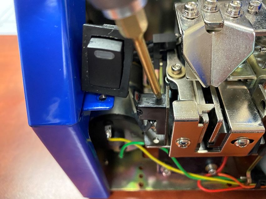
Bit guide & track cover adjustment. Regolazione guida inserto e copri corsia.
To pick the screw up, the bit guide should be Per prelevare la vite correttamente, la guida
centered on the screw head (see picture inserto va centrata sulla testa della vite
below). It’s also possible to adjust it right/left stessa (come da figure).
and forward/backward. The height of the track
cover should be also adjusted so that only the Va regolata anche l’altezza del copri corsia in
screws in the correct position could go modo tale da far passare solo le viti in
through it. posizione corretta.
Procedura:
Procedure:
Per la regolazione della guida inserto
To adjust the bit guide, loosen A screws. allentare le viti A, trovare la corretta posizione
Then find the correct position through the bit aiutandosi con l'inserto che utilizzeremo,
we will use and tighten A screws again. quindi fissarle nuovamente.
Vers. 280421 10Adjustments Regolazioni
To adjust the height of the track cover/bit Per regolare l’altezza del blocco copri corsia/
guide block, loosen C screws through D guida inserto, allentare le viti C,inserendo la
holes. chiave esagonale nei fori D.
.
a
Turn the B screw clockwise to decrease or Agire sulla vite B, in senso orario per
counterclockwise to raise it. Once you have abbassarlo o in senso antiorario per alzarlo.
found the right spot, fix D screws. Dopo aver trovato il punto corretto fissare le
viti D.
The track cover/guide insert should be Il copri corsia-guida inserto deve essere
adjusted horizontally and parallel to the screw regolato in posizione orizzontale e parallelo
heads leaving a few millimeters apart as alle teste delle viti lasciando alcuni millimetri
shown in the following figures. di distanza come mostrato nelle figure
successive.
Vers. 280421 11Adjustments Regolazioni
Speed adjustment. Regolazione velocità.
To adjust the vibration speed and the speed E’ possibile regolare la velocità d’uscita delle
of movement of the brush/ loading wheel viti (vibrazione) e la velocità di movimento
depends on the use and on the type of screw. della spazzola/ruota di carico in base al tipo
di vite e di utilizzo.
M trimmer adjusts the vibration speed, while
N trimmer adjusts simultaneously the speed Il trimmer M regola la velocità d’uscita,
of the brush and of the wheel of charge. For mentre il trimmer N regola
both the trimmer, if turned clockwise, the contemporaneamente la velocità della
speed increases, anticlockwise it decreases. spazzola e la velocità della ruota di carico.
Per entrambi i trimmer, se ruotati in senso
orario la velocità aumenta, in senso antiorario
diminuisce.
Vers. 280421 12Adjustments Regolazioni
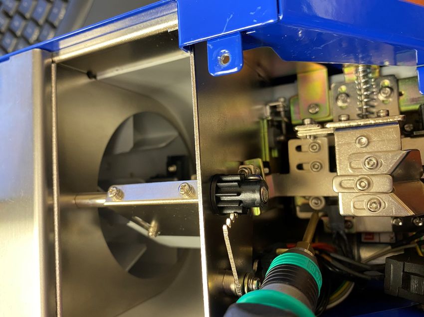
Track adjustment. Regolazione corsia.
Track of NFK-UNI can be adjusted from M1 to La corsia dell’NFK-UNI puo’ essere tarata per
M5 screws (1,4 ÷ 5,3 mm). viti da M1 a M5 (1,4 ÷ 5,3 mm di larghezza).
Procedure Procedura.
Open the E gate (it could prevent the Allargare il gate-blocca viti E (potrebbe
widening of the track), using F screw. Turn impedirebbe l'allargamento della corsia),
the screw clockwise to widen the gate and utilizzando la vite esagonale F. Avvitare in
counterclockwise to close it. senso orario per allargare il gate ed in senso
antiorario per chiuderlo.
A
Loosen H and L screws, load in G and i two Allentare le viti H e L, inserire nei punti G e i
of the screws you're going use. They will be a della corsia 2 delle viti che utilizzerete (viti
reference for the adjustments. che caricheremo nell’NFK come riferimento).
Vers. 280421 13Adjustments Regolazioni
Bring near the 2 sides of the track with the Avvicinare le 2 parti della corsia aiutandoci
help of your fingers until you find the correct con le dita, fino a trovare la distanza corretta
distance of 0.3/0.5 mm larger than the circa di 0.3/0.5 mm maggiore rispetto al
diameter of the screw. diametro della vite.
Tighten H and L screws. Slide a screw Fissare le viti H e L.
through the track: if it should not flow Far scorrere una vite per la corsia
smoothly, repeat the procedure. controllando la corretta distanza. Se la vite
a non dovesse scorrere bene, ripetere la
Close E gate by turning counterclockwise F procedura.
screw. Leave about 1 mm between the gate
and the track. Chiudere nuovamente il gate blocca viti E,
girando la vite nel foro F in senso antiorario.
Re-adjust the bit guide and the cover track Lasciare circa 1 mm di spazio tra il gate e la
each time you change screw type/size. corsia.
È necessario regolare nuovamente il
guida inserto ed il copri corsia ad ogni
cambio di vite.
Vers. 280421 14Troubleshooting Risoluzione dei problemi
ERRORE CAUSA SOLUZIONE
L’NFK non si accende L’alimentatore AC/DC non Collegare l’alimentatore
è collegato all’NFK e alla presa di
corrente
Il tasto di accensione è in Premere ON nel tasto di
posizione OFF accensione
L’NFK è acceso ma le viti Viti con specifiche errate Verificarne le dimensioni
non escono e tarare correttamente
l’NFK
Copri corsia regolato Controllarne la taratura
troppo basso del copri corsia
Velocità di uscita troppo Aumentare la velocità
bassa
Materiale esterno caduto Pulire serbatoio e corsia
nel serbatoio
Viti bloccate nella corsia Spazzola, corsia, copri Tararli nuovamente
corsia in posizione errata
PROBLEM CAUSE COUNTERMEASURES
NFK does not turn ON The AC/DC adapter is not Connect the AC/DC
connected to the power adapter to the power
source source
The power switch is set Set on ON the power
on OFF switch
NFK is set on ON but Screws not suitable Check the screw size and
screws don’t exit properly calibrate the
NFK
Track cover adjusted too Adjust the track cover
low again
Exit speed too low Increase the speed
Foreign material inside Clean the storage and the
the storage track
Screws stuck in the track Brush, track, cover track Adjust them again
in wrong position
Vers. 280421 15Puoi anche leggere