Impianto integrato a CO2 pompata ed espansione diretta
←
→
Trascrizione del contenuto della pagina
Se il tuo browser non visualizza correttamente la pagina, ti preghiamo di leggere il contenuto della pagina quaggiù
the one solution

  Impianto integrato a CO2 pompata
  ed espansione diretta
  Risparmio energetico e riduzione impatto ambientale

  Integrated CO2 system with pumping unit
  and direct expansion
  Energy saving and reduced environmental impact

I n t e g r a t e d   C o n t r o l   S o l u t i o n s   &   E n e r g y   S a v i n g s
ITA
                                                                            Introduzione

                                                                                                                        3

In un’ottica di innovazione e ricerca continua verso il risparmio energetico e l’utilizzo di fluidi frigorigeni
naturali, è stato recentemente realizzato un impianto in cascata che utilizza esclusivamente anidride
carbonica (R744, CO2) come fluido vettore refrigerante per le utenze.
CREA S.p.A. ha realizzato l’impianto sia in termini di concept che di progettazione, costruzione ed installazione
delle unità principali: chiller, centrale frigorifera, piping e regolazione di sistema.
L’azienda CREA rappresenta la leadership nel campo della progettazione e realizzazione di gruppi frigoriferi
centralizzati e di centrali frigorifere per grandi centri di distribuzione.
I servizi che fornisce oggi ai suoi clienti sono frutto di una pluriennale esperienza, che le permette di operare
in modo completo: dalla progettazione al servizio di installazione e manutenzione.
Partner di progetto sono stati ALFAPROJEkT e CAREL S.p.A.
L’installazione ha avuto come obiettivi principali:
• verificare l’effettivo risparmio energetico della soluzione;
• dimostrare la fattibilità d’impianti utilizzanti CO2 come unico fluido vettore del freddo;
• utilizzo di una soluzione a basso impatto ambientale: minimizzazione della carica di fluido frigorigeno
   (HFC utilizzata esclusivamente per il raffreddamento della CO2).

Case Study: Impianto a CO2 pompata ed espansione indiretta                                +402200180 - 1.0 09.09.2008
Soluzione impiantistica
4
La collaborazione tra CREA, ALFAPROJEKT e CAREL ha dato origine alla realizzazione di questa particolare
soluzione impiantistica.
L’impianto è costituito da un chiller a R404A (Fig.1) avente quattro circuiti indipendenti per il raffreddamento
della CO2 che giunge a un serbatoio, il quale raccoglie l’R744 di ritorno in parte dalle utenze TN, in parte dai
compressori della centrale BT.
Il fluido vettore è inviato agli evaporatori dei cabinet e delle celle tramite l’utilizzo di un gruppo di pompaggio.
La CO2 liquida arriva alle utenze di media temperatura senza subire alcuna espansione, mentre le utenze di
bassa presentano al loro ingresso una valvola di espansione elettronica indispensabile al fine di portare
quest’ultime in temperatura.
Il chiller deve quindi essere in grado di scaricare il carico frigorifero degli utilizzatori TN più il calore di
condensazione della centrale BT.
Il gas saturo della CO2 condensa in quattro scambiatori a piastre cedendo calore al R404a espanso a sua volta
tramite valvole elettroniche.
Le centrali montano il rack controller pCO con software personalizzato e proprietario CREA.
La selezione delle centrali è stata fatta in base alla richiesta frigorifera che è:
• 60 kW per l’impianto TN, 19 utenze;
• 15 kW per l’impianto BT, 5 utenze.
Il gruppo di pompaggio è stato dimensionato in base alla totale potenza frigorifera richiesta. Il sistema
monta due pompe l’una di scorta all’altra per avere la massima affidabilità, in caso di manutenzione o
malfunzionamento.
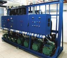
Centrale frigorifera CREA
Case Study: Impianto a CO2 pompata ed espansione indiretta +402200180 - 1.0 09.09.2008ITA
5
1
2 3
4
6
5
Fig. 1
Legenda Fig. 1:
1. chiller R404a;
2. serbatoio CO2;
3. centrale BT CO2;
4. pompa;
5. valvola solenoide, MPXPRO;
6. E2V, MPXPRO
Case Study: Impianto a CO2 pompata ed espansione indiretta +402200180 - 1.0 09.09.2008Controllo e gestione
dell’impianto
6
L’intera gestione dell’impianto è stata affidata alla serie “CAREL retail sistema” con l’utilizzo del sistema di
supervisione remoto PlantVisorPRO integrata con soluzioni customizzate CREA.
L’utilizzo della soluzione integrata “CAREL retail sistema” per l’impianto di refrigerazione consente di ottenere
il massimo vantaggio dalle funzionalità di risparmio energetico, disponibili nei diversi controlli dedicati alla
regolazione dell’impianto.
L’ottima progettazione e messa in opera dell’installazione è cosa fondamentale ai fini di un ottimo risultato,
anche in termini di controllo dello stesso.
Le utenze TN montano all’ingresso degli evaporatori delle elettrovalvole gestite dal controllore MPXPRO che
apre o chiude le valvole in funzione della temperatura dell’utilizzatore.
Le utenze BT necessitano invece di un’espansione del fluido refrigerante, per tale motivo all’ingresso degli
evaporatori si trovano le valvole elettroniche E2V CAREL gestite sempre dal controllore MPXPRO.
Il sistema chiller è gestito dal rack controller della serie pCO sistema di CAREL con un software personalizzato
CREA per la gestione dei quattro circuiti frigoriferi. Il refrigerante R404a è espanso nei quattro scambiatori di
calore a piastre per mezzo delle valvole elettroniche E2V gestite dal controllore CAREL EVD.
La centrale frigorifera di bassa temperatura a CO2 è gestita dal rack controller con software di gestione
personalizzato CREA appartenente alla serie pCO sistema.
Case Study: Impianto a CO2 pompata ed espansione indiretta +402200180 - 1.0 09.09.2008ITA
Stime dei consumi fra diversi
sistemi
7
La stima dei consumi elettrici annui di diverse tipologie d’impianto (Tab. 1), consente di verificare quali sono
gli effettivi vantaggi della soluzione adottata per il punto vendita oggetto di questo studio.
Sono state analizzate le seguenti diverse soluzioni impiantistiche:
• impianto standard con valvole d’espansione termostatiche (Fig.2);
• impianto standard con valvole di espansione elettroniche e conseguente logica di regolazione (utilizzo
del setpoint di condensazione flottante in funzione della temperatura ambiente) (Fig.3);
• impianto in cascata classico con CO2 come fluido secondario. La centrale frigorifera di media temperatura
ad R404A, alimenta le utenze frigorifere di media ed inoltre condensa la CO2 proveniente dalla centrale
frigorifera di bassa temperatura. Per l’espansione del fluido in quest’ultime utenze sono utilizzate le valvole
di espansione elettroniche (Fig.4);
• impianto in cascata definito “New Concept”, si tratta del sistema oggetto di questa installazione, descritto
precedentemente (Fig.1).
Fig. 2 Fig. 3
Case Study: Impianto a CO2 pompata ed espansione indiretta +402200180 - 1.0 09.09.20088
P T
P T
P T
Fig. 4
Consumi elettrici annui
Consumi annui
Std Std+EEV CO2 Casc. New
Concept
kW/h
Consumo centrale BT 231513 152320 63249 76941
BT Consumo dei 10881 9153 0 0
ventilatori BT
Consumo centrale TN 492576 439339 499116 437105
TN Consumo dei ventilatori TN 37704 36836 42271 40969
Consumo della pompa TN 0 0 0 15768
Potenza Totale Assorbita 772675 637647 604635 570783
Tab. 1
Case Study: Impianto a CO2 pompata ed espansione indiretta +402200180 - 1.0 09.09.2008ITA
Conclusioni
9
Alla luce di quanto esposto e dei dati rilevati (in 6 mesi di funzionamento) dall’impianto oggetto di questa
relazione e da un altro di taglia superiore, si evince che la soluzione impiantistica proposta, oltre che essere
“migliorativa” dal punto di vista ecologico, in quanto riduce al minimo la carica di refrigerante sintetico
soggetto alle regole del Regolamento Europeo 842/2006 (e quindi ai controlli “invasivi” obbligatori), permette
una riduzione sensibile del consumo energetico.
I risultati ottenuti sono di stimolo alla ricerca di ottimizzazione del progetto, ricercando soluzioni più
performanti per ciascuno dei componenti dell’insieme, ovvero centrale frigorifera (compressori, scambiatori,
regolazione elettronica…), utilizzatori (banchi frigoriferi, aereoevaporatori cella). L’obbiettivo è quindi di
continuare la ricerca di soluzioni attuabili nel contesto in cui ci troviamo ad operare ovvero condizioni
climatiche del nostro paese, settore (refrigerazione commerciale) e non ultimo condizioni economiche
(diminuire il rischio dell’investitore, pur mantenendo elevato il livello tecnologico e le performance). Per
questo motivo oltre ad una attività di ricerca e sviluppo tecnico, deve essere portata avanti una opera di
“acculturamento” dell’utente finale per capire che l’investimento non va valutato solo come costo iniziale ma
anche durante tutta la sua vita (costi di manutenzione, dei “controlli obbligatori”, costi energetici…).
Grafico relativo al consumo di energia totale
%
100.0
1
80.0
2
60.0 3
4
40.0
5
20.0
0.0
Std Std+EEV CO2 Casc. New Concept
Fig. 5
Legenda Fig. 5:
1. consumo centrale BT;
2. consumo dei ventilatori BT;
3. consumo centrale TN;
4. consumo dei ventilatori TN;
5. consumo della pompa.
Case Study: Impianto a CO2 pompata ed espansione indiretta +402200180 - 1.0 09.09.2008Note
ENG
                                                                           Introduction

                                                                                                                     3

The latest innovations and continuous research into energy saving and the use of natural refrigerants have
led to the development of a cascade installation that uses only carbon dioxide (R744, CO2) as the refrigerant
for the utilities.
CREA S.p.A. has developed the installation both as regards the concept and the design, construction and
installation of the main units: chiller, compressor rack, piping and system control.
CREA represents a leading company in the design and development of centralised refrigeration units and
compressor racks for large retail centres.
The complete range of services it currently provides its customers are the result of extensive experience:
from design to installation and maintenance.
Partners in the project were ALFAPROJEKT and CAREL S.p.A.
The main objectives of the installation were to:
• verify the effective energy savings of the solution;
• demonstrate the feasibility of systems using CO2 as the only refrigerant fluid;
• use a solution with a low environmental impact: minimising the refrigerant charge (HFC used only for
  cooling the CO2).

Case Study: Integrated CO2 system with pumping unit and direct expansion               +402200180 - 1.0 09.09.2008
Solution
4
The partnership between CREA, ALFAPROJEKT and CAREL led to the development of this specific solution.
The system consists of a chiller operating on R404A (Fig.1), with four independent circuits for cooling the CO2
in a tank that collects the R744 returning partly from the MT units, and partly from the LT compressor rack.
The refrigerant is delivered to the showcase and cold room evaporators by a pumping unit. The liquid CO2
reaches the medium temperature units without undergoing expansion, while the low temperature units
have an electronic expansion valve at the inlet to ensure these reach the right operating temperature.
The chiller must thus be able to handle the cooling capacity of the MT units plus the heat of condensation
of the LT rack.
The saturated CO2 gas condenses in four plate exchangers, transferring heat to the R404a; this in turn is
expanded through electronic valves.
The systems are fitted with the pCO rack controller running customised and proprietary CREA software.
The systems were selected based on the cooling demand, that is:
• 60 kW for the MT system, 19 units;
• 15 kW for the LT system, 5 units.
The pumping unit was sized based on the total cooling capacity. The unit is fitted with two pumps, one of
which in standby, to ensure maximum reliability in the event of maintenance or malfunctions..
CREA compressor rack
Case Study: Integrated CO2 system with pumping unit and direct expansion +402200180 - 1.0 09.09.2008ENG
5
1
2 3
4
6
5
Fig. 1
Key to Fig. 1:
1. R404a chiller;
2. CO2 tank;
3. CO2 LT rack;
4. pump;
5. solenoid valve, MPXPRO;;
6. E2V, MPXPRO
Case Study: Integrated CO2 system with pumping unit and direct expansion +402200180 - 1.0 09.09.2008System control and
management
6
The overall management of the system was entrusted to the “CAREL Retail sistema” series, using the
PlantVisorPRO remote supervisory system integrated with customised CREA solutions.
The integrated “CAREL retail sistema” solution for the refrigeration system was chosen to achieve maximum
advantages in terms of energy saving, available on the different controllers used to manage the system.
Optimum design and commissioning of the system was also fundamental to achieve best results in terms
of operation and control.
The MT units have solenoid valves at the evaporator inlet managed by the MPXPRO controller, which opens
or closes the valves based on the operating temperature.
The LT utilities, on the other hand, require expansion of the refrigerant, and consequently CAREL E2V electronic
valves are installed at the evaporator inlet, again managed by the MPXPRO controller.
The chiller system is managed by the CAREL pCO sistema series rack controller, with customised CREA
software for managing the four refrigerant circuits. The R404a refrigerant is expanded in the four heat plate
exchangers through the E2V electronic valves, managed by the CAREL EVD controller.
The low temperature CO2 compressor rack is managed by the pCO sistema series rack controller, with
customised CREA software.
Case Study: Integrated CO2 system with pumping unit and direct expansion +402200180 - 1.0 09.09.2008ENG
Estimated power consumption
of the different systems
7
The estimated annual power consumption for various different types of system (Table 1) is used to verify the
effective advantages of the solution adopted for the sales outlet in question.
The following different solutions were analysed:
• standard system with thermostatic expansion valves (Fig.2);
• standard system with electronic expansion valves and consequent control logic (use of floating condenser
control set point based on room temperature) (Fig.3);
• classic cascade system with CO2 as secondary fluid. The medium temperature R404A compressor rack
serves the medium temperature refrigeration units and also condenses the CO2 from the low temperature
compressor rack. Electronic expansion valves are used for the expansion of the fluid in these units (Fig.4);
• cascade system defined as “New Concept”, i.e. the system used in this installation, as described previously
(Fig.1).
Fig. 2 Fig. 3
Case Study: Integrated CO2 system with pumping unit and direct expansion +402200180 - 1.0 09.09.20088
P T
P T
P T
Fig. 4
Annual power consumption
Annual consumption
Std Std+EEV CO2 Casc. New
Concept
kW/h
LT rack consumption 231513 152320 63249 76941
LT
LT fan consumption 10881 9153 0 0
MT rack consumption 492576 439339 499116 437105
MT fan consumption 37704 36836 42271 40969
MT
MT pumping unit 0 0 0 15768
consumption
Total power consumption 772675 637647 604635 570783
Tab. 1
Case Study: Integrated CO2 system with pumping unit and direct expansion +402200180 - 1.0 09.09.2008ENG
Conclusions
9
In light of the above and the data measured (over 6 months of operation) at the installation studied in
this report and another larger one, it can be concluded that the solution proposed, as well as being an
“improvement” in environmental terms, by minimising the charge of synthetic refrigerant subject to European
Regulation 842/2006 (and thus compulsory “invasive” checks), also brings a considerable reduction in energy
consumption.
The results achieved represent a stimulus to continue optimising the design, investigating higher performance
solutions for each of the components, that is, the compressor rack (compressors, heat exchangers, electronic
controller…) and the refrigeration units (showcases, cold room evaporators). The objective is therefore to
continue the search for solutions that can be implemented in the context we operate in, that is, the climatic
conditions in our country, the sector (commercial refrigeration) and not least the economic conditions
(reducing investor risk, while maintaining high level of technology and performance). For this reason, as well as
technical research and development, end users must be “educated” to understand that the investment must
not only be evaluated in terms of the cost upfront, but also throughout the life of the system (maintenance
costs, “compulsory checks”, energy costs…).
Graph relating to total energy consumption
%
100.0
1
80.0
2
60.0 3
4
40.0
5
20.0
0.0
Std Std+EEV CO2 Casc. New Concept
Fig. 5
Key to Fig. 5:
1. LT rack consumption;
2. LT fan consumption;
3. MT rack consumption;
4. MT fan consumption;
5. pumping unit consumption.
Case Study: Integrated CO2 system with pumping unit and direct expansion +402200180 - 1.0 09.09.2008Note
CREA S.p.A.
via Bergamo, 80
20040 Bellusco - Milano
tel. 039-6022784 - fax 039-6022671
e-mail: creaspa@creaspa.it
www.creaspa.it
Headquarters ITALY

                                                                                                                                                         +402200180 - 1.0 - 09.09.2008
CAREL S.p.A.
Via dell’Industria, 11 - 35020 Brugine - Padova (Italy)
Tel. (+39) 0499 716611 - Fax (+39) 0499 716600
carel@carel.com - www.carel.com

Sales organization                                        Affiliates

CAREL Asia                                                CAREL Korea
www.carel.com                                             www.carel.co.kr

CAREL Australia                                           CAREL Ireland
www.carel.com.au                                          FarrahVale Controls & Electronics Ltd.
                                                          www.carel.com
CAREL China
www.carel-china.com                                       CAREL Czech & Slovakia
                                                          CAREL spol. s r.o.
CAREL South Africa                                        www.carel-cz.cz
CAREL Controls S.A. (Pty)
www.carelcontrols.co.za                                   CAREL Thailand
                                                          www.carel.co.th
CAREL Deutschland
www.carel.de                                              CAREL Turkey
                                                          CFM Sogutma ve Otomasyon San. Tic. Ltd.
CAREL France                                              www.carel.com.tr
www.carelfrance.fr

CAREL Ibérica
Automatización y Control ATROL S. L.
www.carel.es

CAREL India
CAREL ACR Systems India (Pvt) Ltd.
www.carel.com

CAREL Sud America
www.carel.com.br

CAREL U.K.
www.careluk.co.uk

CAREL U.S.A.
www.carelusa.com

                                                                                                    All trademarks hereby referenced are
                                                                                                    the property of their respective owners.
                                                                                                    CAREL is a registered trademark of
                                                                                                    CAREL S.p.A. in Italy and/or other countries.

www.carel.com                                                                                       © CAREL S.p.A. 2008 all rights reserved

                                                                                                    CAREL reserves the right to modify the features of its
                                                                                                    products without prior notice.
Puoi anche leggere