DREAMLIGHT 250 ECLIPSE SPOT - PLML250SE
←
→
Trascrizione del contenuto della pagina
Se il tuo browser non visualizza correttamente la pagina, ti preghiamo di leggere il contenuto della pagina quaggiù
DREAMLIGHT 250 ECLIPSE SPOT
          PLML250SE
INDICE
INTRODUZIONE ....................................................................... 2
CARATTERISTICHE................................................................... 2
NORME DI SICUREZZA........................................................... 4
CONDIZIONI OPERATIVE....................................................... 5
INSTALLAZIONE / SOSTITUZIONE LAMPADA ................ 6
REGOLAZIONE LAMPADA .................................................... 8
INSTALLAZIONE....................................................................... 9
CONNESSIONE DMX.............................................................10
CONNESSIONE ALLA RETE DI ALIMENTAZIONE..........11
FUNZIONI CANALI.................................................................12
INDIRIZZAMENTO .................................................................14
FUNZIONI MENU DISPLAY..................................................14
CARATTERISTICHE TECNICHE............................................17
PULIZIA E MANUTENZIONE ...............................................18
SOSTITUZIONE FUSIBILE.....................................................18
Tutte le specifiche riportate nel presente manuale sono soggette a variazioni
senza preavviso
Rev. 00 – 49/2007ATTENZIONE
TENERE QUESTO APPARECCHIO LONTANO DA PIOGGIA E UMIDITÀ.
SCOLLEGARE IL CAVO DALLA RETE DI ALIMENTAZIONE PRIMA DI APRIRE IL
COPERCHIO.
PER LA VOSTRA SICUREZZA, LEGGERE ATTENTAMENTE QUESTO MANUALE
PRIMA DI ACCENDERE L’APPARECCHIO PER LA PRIMA VOLTA.
Chiunque si occupi dell’installazione, uso e manutenzione di questo
apparecchio deve:
- essere una persona qualificata
- seguire le istruzioni riportate sul presente manuale.
INTRODUZIONE
Grazie per aver scelto la testamobile PLML250SE. Vi renderete presto conto di
aver acquistato un apparecchio potente, versatile e dall’ottima qualità.
Una volta tolto dall’imballo la testamobile PLML250SE, prima di accenderlo per
la prima volta, sinceratevi che non vi siano danni provocati dal trasporto. Se ve
ne fossero, contattate il vostro rivenditore di fiducia e non utilizzate questo
apparecchio.
CARATTERISTICHE
- Sistema colori: 1 ruota colori con 9 differenti filtri dicroici più bianco.
- Effetto rainbow in entrambe le direzioni.
- Ruota gobo con 6 gobo rotanti e facilmente intercambiabili.
- Prisma a tre facce con la possibilità di ruotare in entrambe le direzioni
- Unità shutter/dimmer combinata che permette un’operazione dimmer anche
durante l’effetto strobo.
- Sequenze demo incorporate. Macrofunzioni per combinazioni di colori.
- Possibilità di blackout durante il movimento della testa.
- Funzione reset a distanza.
- Ventole di raffreddamento silenziose.
- Movimento di PAN/TILT con una risoluzione di 16 bit.
- PAN 530°, TILT 280°.
- Ripristino automatico della posizione di PAN/TILT attraverso encoder.
- Messa a fuoco motorizzata.
21
2
3
4
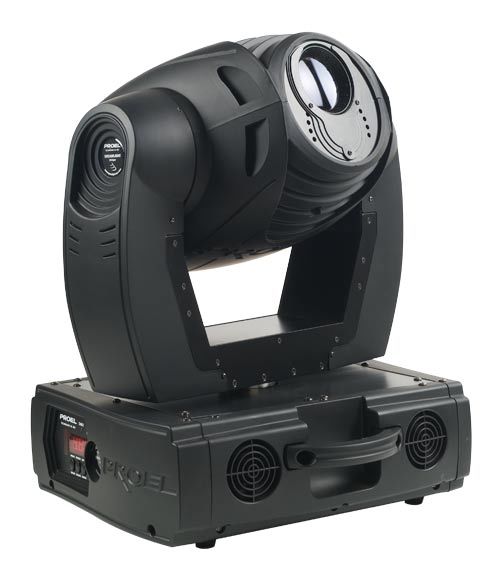
1: Obiettivo
2: Semiscocca testa
3: Maniglia per la movimentazione
4: Display LED
3NORME DI SICUREZZA
ATTENZIONE: PRESTARE PARTICOLARE ATTENZIONE ALLE OPERAZIONI DA
EFFETTUARE. CON L’ALTA TENSIONE POTRESTE SUBIRE PERICOLOSI SHOCK
ELETTRICI TOCCANDO I CAVI.
Questo apparecchio ha lasciato i nostri stabilimenti in condizioni assolutamente
perfette. Per mantenerle tali e per effettuare operazioni in sicurezza, è
importante che l’utente segua le istruzioni di sicurezza e gli avvertimenti
riportati in questo manuale utente.
IMPORTANTE: danni provocati dalla noncuranza di questo manuale, non sono
soggetti a garanzia.
Se l’apparecchio è stato esposto a grandi variazioni di temperatura (per es. dopo
il trasporto), non accenderlo immediatamente. La condensa che si forma
potrebbe danneggiare il Vostro apparecchio. Lasciare spento l’apparecchio fin
quando non abbia raggiunto la temperatura ambiente.
Questo apparecchio appartiene alla CLASSE DI PROTEZIONE I, pertanto la spina
di alimentazione va collegata soltanto a prese che prevedono la protezione di
classe I (collegamento a massa).
Non lasciare il cavo di alimentazione a contatto con altri cavi. Maneggiare il cavo
di alimentazione e tutte le connessioni con la rete principale, prestando
particolare attenzione.
Assicurarsi che la tensione a disposizione non sia superiore a quella specificata
sul panello posteriore.
Assicurarsi che il cavo di alimentazione non sia deformato o danneggiato da
oggetti taglienti. Controllare periodicamente lo stato dell’apparecchio e del
cavo di alimentazione.
Disconnettere sempre l’apparecchio dalla rete di alimentazione, quando non
usato o prima di pulirlo. Per scollegare dalla rete il cavo di alimentazione
impugnare la spina, mai tirare il cavo.
Alla prima accensione potrebbe presentarsi un po’ di fumo e un leggero odore
di bruciato. Tutto ciò è normale e ciò non significa necessariamente che
l’apparecchio sia difettoso.
ATTENZIONE: durante il normale funzionamento l’involucro esterno diventa
molto caldo.
PERICOLO DI INCENDIO: non installare mai l’apparecchio su una superficie
altamente infiammabile (per es. tappeti)
4RISCHI PER LA SALUTE: non guardare mai direttamente all’interno della sorgente
di luce, persone sensibili potrebbero avere uno shock epilettico.
Non accendere e spegnere in ristretti intervalli di tempo perché ciò riduce il
tempo di vita della lampada considerate che danni causati da modifiche manuali
all’apparecchio non sono soggetti a garanzia.
Tenere lontano dalla portata dei bambini o di persone non esperte.
CONDIZIONI OPERATIVE
Il prodotto può funzionare soltanto con alimentazione in corrente alternata
230V – 50Hz (120V 60Hz) ed è destinato al solo uso interno.
Questo apparecchio è indicato per uso professionale ad es. palcoscenici,
discoteche, teatri, ecc.
Tale effetto non è indicato per un uso ininterrotto. Durante i periodi di
prolungato non utilizzo è consigliabile disconnetterlo dall’alimentazione, ciò
assicurerà una durata di vita prolungata senza problemi.
Proteggere l’apparecchio da urti o shock improvvisi, sia in fase di installazione
che di normale funzionamento.
Non accendere mai l’apparecchio senza la lampada.
Non scuotere l’apparecchio. Evitare forzature quando si istalla l’apparecchio o
quando si opera con esso.
Non sollevare mai l’apparecchio dai bracci, in quanto le parti meccaniche
potrebbero subire danni. Per il trasporto, usare le apposite maniglie.
La minima distanza fra il punto di emissione del fascio luminoso e la superficie
illuminata deve essere maggiore di un metro.
Nella scelta del punto di installazione del proiettore, evitare luoghi con
temperature elevate, con elevato tasso di umidità e polvere; evitare zone dove si
trovano cablaggi circostanti. Potreste mettere in pericolo sia la vostra che la
sicurezza altrui.
5Fissare sempre l’apparecchio con un’adeguata fune di sicurezza. Fissare tale fune
tramite il corretto punto di fissaggio al di sotto della base e non tramite le
maniglie di trasporto.
Mettere in funzione l’apparecchio solo dopo essersi assicurati che la scocca
esterna sia saldamente chiusa e tutte le viti siano correttamente serrate.
La lampada non deve mai essere accesa se le lenti dell’obbiettivo o parti del
coperchio sono state rimosse: la lampada a scarica, infatti, se non
adeguatamente protetta, emette radiazioni ultraviolette dannose per la pelle
(ustioni) e per gli occhi (congiuntiviti).
La massima temperatura ambiente raccomandata (Ta = 40 °C) non deve mai
essere superata.
ATTENZIONE le lenti devono essere sostituite quando sono danneggiate o risulti
compromessa la loro funzionalità.
Operare con quest’apparecchio solo dopo aver familiarizzato con le sue funzioni.
Non permettere che personale non qualificato possa utilizzare la testamobile:
molti danni infatti sono provocati da un uso improprio.
ATTENZIONE la lampada deve essere sostituita quando è danneggiata.
Usare sempre l’imballo originale per il trasporto.
Modifiche non autorizzate dell’apparecchio, sono vietate per ragioni di
sicurezza.
Non rimuovere il codice a barre dall’apparecchio per la garanzia
Se il proiettore dovesse trovarsi ad operare in condizioni differenti da quelle
descritte nel presente manuale, potrebbero verificarsi dei danni; in tal caso la
garanzia verrebbe a decadere, inoltre ogni altra operazione potrebbe provocare
cortocircuiti, incendi, scosse elettriche, esplosioni della lampada, rotture ecc.
INSTALLAZIONE / SOSTITUZIONE LAMPADA
PERICOLO: installare la lampada solo quando l’apparecchio è spento e il cavo di
alimentazione è scollegato dalla rete
6Utilizzare lampade HSR250/MSR250 o equivalenti, rispettandone le specifiche
del costruttore.
ATTENZIONE: la lampada deve essere sostituita quando è danneggiata o
deformata a causa del calore.
Durante il normale funzionamento, la lampada raggiunge temperature superiori
a 600°C.
Prima di sostituire la lampada, scollegare l’alimentazione e attendere che la
stessa si raffreddi (circa 10 min.)
Durante l’installazione della nuova lampada non toccare il bulbo in vetro con le
mani nude. Seguire le indicazioni del costruttore
Non installare lampade con una potenza maggiore di quella indicata. Queste
infatti generano elevate temperature, che la testamobile non è progettato per
sopportare.
Danni provocati da noncuranze di questo tipo causano la decadenza della
garanzia
7PROCEDIMENTO
Svitare le tre viti di fissaggio della semiscocca in plastica superiore della testa
con un giravite a croce (VEDI DISEGNO).
Rimuovere lo chassis e individuare il coperchio in metallo del gruppo ottico.
Svitare le due viti A e B a mano e rimuovere il coperchio.
Inserire la lampada nuova nel portalampada facendo attenzione a non avere un
contatto diretto del bulbo con le dita.
Riavvitare il coperchio in metallo e poi lo chassis della testa facendo attenzione a
far combaciare la parte superiore con quella inferiore.
Regolare la lampada se necessario come descritto più avanti
VITI SEMISCOCCA
SUPERIORE
VITI
A B
COPERCHIO IN METALLO
DEL GRUPPO OTTICO
NON ACCENDERE L’APPARECCHIO FINCHÉ L’ALLOGGIAMENTO DELLA
LAMPADA NON SIA CHIUSO.
REGOLAZIONE LAMPADA
La lampada viene già centrata in fabbrica. A causa di differenze tra le varie
lampade, una ulteriore regolazione fine potrebbe migliorare la qualità luminosa.
Accendere la lampada, aprire lo shutter e l’iris, portare l’intensità del dimmer al
100% e mettere a fuoco l’impronta luminosa su una superficie piana (es. muro).
Centrare la parte più luminosa del raggio usando le due viti di regolazione (A e
B). Girare una vite alla volta in modo da veder scorrere il centro luminoso del
raggio lungo la diagonale dell’impronta luminosa sul muro. Nel caso non si
8riesca a distinguere la parte più luminosa del raggio, regolare la lampada, fin
quando l’impronta luminosa non sia uniforme.
Per ridurre l’intensità del centro
luminoso, tirare la lampada verso il
riflettore, girando la vite A in senso orario
¼ di giro alla volta fino a quando la luce
non sia uniformemente distribuita.
Se l’impronta è più luminosa intorno al
bordo rispetto al centro, o la luminosità è
bassa, la lampada è troppo vicina al
fondo della parabola. Spingere la
lampada girando la vite A in senso
antiorario ¼ di giro alla volta fino a
quando la luminosità sia maggiore ed
uniformemente distribuita.
INSTALLAZIONE
PERICOLO: durante l’installazione considerare sempre le norme del proprio
Stato. L’installazione deve essere sempre eseguita da personale autorizzato.
L’installazione del proiettore deve essere sempre resa sicura attraverso un
ancoraggio secondario di sicurezza. Questo deve essere fatto in modo che
niente possa cadere nell’eventualità che l’ancoraggio principale venga meno.
Durante il montaggio, lo smontaggio o la manutenzione, è vietato sostare
nell’area al di sotto della zona dell’installazione, sopra ponteggi, sotto aree ad
alta densità lavorativa o in qualsiasi altra zona pericolosa.
L’operatore deve preoccuparsi che tutto quanto riguardante la sicurezza e le
caratteristiche tecniche delle macchine, sia stato approvato da persona esperta
prima di iniziare le operazioni per la prima volta o, in seguito a cambiamenti,
prima di avviare le operazioni di nuovo.
IMPORTANTE: INSTALLAZIONI IN ALTO RICHIEDONO MOLTA ESPERIENZA
relativamente ai calcoli sui carichi limite di lavoro, a tutto il materiale usato
nell’installazione ed ai controlli di sicurezza periodici su tutto quanto usato
nell’installazione (attrezzature e proiettori). Mancando tali requisiti, non tentare
mai di eseguire l’installazione da soli, ma rivolgersi sempre a personale
qualificato. Una errata installazione può provocare anche danni fisici e/o
economici.
9Il proiettore deve essere installato al di
fuori della portata delle persone.
Se la posizione del proiettore dovesse
essere più bassa rispetto al soffitto o a travi
alte, bisognerà utilizzare truss professionali.
Il proiettore non deve mai essere fissato in
modo che oscilli liberamente nella stanza.
ATTENZIONE: Il proiettore potrebbe
provocare gravi danni in caso di caduta. In
presenza di qualsiasi dubbio riguardante la
sicurezza della possibile installazione, non
installare il proiettore.
RISCHIO DI INCENDIO: al momento dell’installazione del proiettore assicurarsi
che non ci siano superfici infiammabili a distanza inferiore a 1 m
ATTENZIONE: Usare 2 ganci appropriati per fissare l’apparecchio ad una truss.
Avvitare ciascun gancio con una vite M12 ai sostegni ad omega. Fissare il primo
sostegno ad omega sulla parte inferiore della base, utilizzando gli attacchi rapidi
in dotazione. Per il fissaggio di questi, inserirli negli appositi fori, girare in senso
orario fino allo scatto. Allo stesso modo fissare il secondo sostegno.
Assicurarsi che il fissaggio dell’apparecchio sia effettuato correttamente;
Assicurarsi che la struttura (es. truss) alla quale viene fissato l’apparecchio sia
sicura. La testamobile può essere appoggiato sia direttamente sul palco che
ancorato ad una truss con una qualsiasi orientazione, senza alterarne le funzioni
(vedere disegno).
Per l’uso in alto installare sempre una adeguata fune di sicurezza facendola
passare attraverso il foro posto al di sotto della base. Usare la fune di sicurezza
esclusivamente ad anello chiuso, non usarla mai assicurando soltanto i due capi.
La massima distanza di caduta (dopo la quale deve intervenire la fune) non deve
mai superare i 20 cm.
Una fune di sicurezza, già sottoposta a tensione a causa di una caduta di un
proiettore, o comunque danneggiata, non deve essere mai riutilizzata.
CONNESSIONE DMX
I cavi DMX non devono venire a contatto con altri cavi, in tal caso infatti gli
apparecchi potrebbero non funzionare correttamente o non funzionare affatto.
10Usare solo cavi stereo schermati con spina e presa tipo XLR 3 poli, per la
connessione alla centralina DMX o per il collegamento tra apparecchi.
SCHEMA DI CONNESSIONE DEI CAVI DMX:
DMX-output DMX-input
presa XLR spina XLR
Utilizzando centraline DMX con questo schema per i connettori, è possibile
connettere l’uscita DMX della centralina all’ingresso DMX del primo proiettore
della catena DMX. Se si desidera connettere una centralina DMX con un altro
tipo di uscita XLR (es. 5 poli), è necessario disporre di un adattatore.
CREAZIONE DI UNA CATENA DMX
Connettere l’uscita DMX del primo apparecchio della catena, all’ingresso DMX
dell’apparecchio successivo. Procedere allo stesso modo fino alla totale
connessione degli apparecchi.
ATTENZIONE: Per installazioni in cui il cavo di
segnale deve percorrere lunghe distanze o dove
vi sono disturbi elettrici, per esempio in
discoteca, è consigliato l’uso di una
terminazione DMX. Il terminatore DMX è
semplicemente un connettore XLR con
collegato ad esso una resistenza da 120Ω (Ohm)
tra i piedini 2 e 3. La resistenza viene innestata
nella presa di uscita DMX dell’ultimo proiettore
della catena. La connessione è illustrata a destra.
CONNESSIONE ALLA RETE DI ALIMENTAZIONE
Collegare l’apparecchio alla rete di alimentazione, attraverso il cavo incluso nella
confezione. Lo schema di connessione di tale cavo è il seguente:
11Cavo Pin Simbolo
marrone fase L
blu neutro N
giallo/verde terra
La terra deve essere connessa.
Il proiettore non deve essere connesso ad un dimmer-pack.
FUNZIONI CANALI.
CANALE 1: MOVIMENTO ORIZZONTALE (PAN).
Portare su il relativo slider per muovere orizzontalmente la
testa (PAN).
La testa può essere ruotata di 530° e può essere fermata in
qualsiasi posizione intermedia desiderata.
CANALE 2: MOVIMENTO VERTICALE (TILT).
Portare il relativo slider per muovere verticalmente la testa
(TILT). La testa può essere ruotata di 280° e può essere
fermata in qualsiasi posizione intermedia desiderata.
CANALE 3: MOVIMENTO ORIZZONTALE FINE.
CANALE 4: MOVIMENTO VERTICALE FINE.
CANALE 5: VELOCITÀ DI PAN/TILT.
Regolazione della velocità dei movimenti PAN / TILT e funzione di black out
durante movimento della testa.
CANALE 6: RESET.
12CANALE 7: RUOTA COLORI.
La ruota colori è composta dai seguente colori
Bianco
Rosso
Giallo
Viola
Verde
Arancione
Blu
Rosa
Blu scuro
Ciano
Rainbow
CANALE 8: RUOTA GOBO.
Questo canale inserisce la proiezione di un gobo nel fascio luminoso e per
scegliere il disegno tra 6 differenti gobo (4 metallici e 2 dicroici) che possono
essere facilmente e velocemente sostituiti da altri a piacimento.
CANALE 9: ROTOGOBO
Questo canale permette attivare la rotazione di un gobo. Sempre lo stesso
canale consente di regolare la velocità e il verso di rotazione dei gobo.
CANALE 10: EFFETTTO STROBO.
Tramite il questo canale è possibile attivare l’apertura delle palette dello shutter
per simulare una luce stroboscopica. Sempre lo stesso canale permette di
regolare la velocità dello strobo fino a 10 flash per secondo.
CANALE 11: DIMMER.
Questo canale regola linearmente l’apertura delle palette dello shutter dal
blackout totale all’apertura completa dello shutter.
CANALE 12: PRISMA.
Questo canale abilita il prisma a tre facce.
13CANALE 13: ROTOPRISMA
Canale dedicato alla rotazione del prisma. Tramite questo canale è possibile
decidere la velocità di rotazione ed il verso della ruota colori
CANALE14: FOCUS.
Canale che comanda la messa a fuoco automatica.
INDIRIZZAMENTO
Il Pannello di controllo sul lato anteriore del PLML250SE vi permette di
assegnare all’apparecchio l’indirizzo DMX dal quale l’apparecchio risponderà al
controllore.
Se per esempio settate come indirizzo il canale 5 il PLML250SE userà i canali da 5
a 18 per il controllo.
Assicurarsi che non ci siano canali sovrapposti in modo da poter controllare ogni
PLML250SE separatamente e in modo indipendente.
Se due o più PLML250SE sono indirizzati con gli stessi canali essi lavoreranno
allo stesso modo.
Per settare l’indirizzo seguire la seguente procedura:
- Accendere il PLML250SE e attendere che l’apparecchio esegua il reset.
- Premere i tasti “UP” e “DOWN” fino a quando il display mostra la lettera A + il
valore del canale desiderato. Confermare premendo “ENTER” e la lettera “A”
lampeggerà.
FUNZIONI MENU DISPLAY
COLOR SLOPE
Tramite questa funzione è possibile impostare la rotazione lineare della ruota
colori che permette il posizionamento del “mezzo colore”. Per attivare la
modalità Color Slope, premere il tasto MODE e posizionarsi alla voce F1. Premere
il tasto UP e premere ENTER quando sul display è visualizzato Y. Per disabilitare
la funzione scegliere N e premere ENTER per confermare.
PAN REVERSE
Tramite questa funzione è possibile invertire il verso di rotazione del movimento
del PAN. Per attivare la modalità PAN Reverse, premere il tasto MODE e
posizionarsi alla voce F2. Premere il tasto UP e premere ENTER quando sul
display è visualizzato Y. Per disabilitare la funzione scegliere N e premere ENTER
per confermare.
14TILT REVERSE Tramite questa funzione è possibile invertire il verso di rotazione del movimento del TILT. Per attivare la modalità TILT Reverse, premere il tasto MODE e posizionarsi alla voce F3. Premere il tasto UP e premere ENTER quando sul display è visualizzato Y. Per disabilitare la funzione scegliere N e premere ENTER per confermare. DEMO OPERATION È possibile far funzionare la testamobile anche senza collegare la stessa ad una centralina. Per attivare la modalità Demo Operation, premere il tasto MODE e posizionarsi alla voce F4. Premere il tasto UP e premere ENTER quando sul display è visualizzato Y. Per disabilitare la funzione scegliere N e premere ENTER per confermare. RESET È possibile fare il reset della testamobile anche senza collegare la stessa ad una centralina. Per attivare il reset, premere il tasto MODE e posizionarsi alla voce F5. Premere il tasto UP e premere ENTER quando sul display è visualizzato Y. Per disabilitare la funzione scegliere N e premere ENTER per confermare. CONTROLLI Dopo aver indirizzato tutti i PLML250SE si possono iniziare le operazioni attraverso la centralina delle luci. 15
Note:
Dopo avere acceso il proiettore, lo stesso controllerà automaticamente se sta
ricevendo i dati dal DMX o no. Se non ci sono dati in input sul display inizierà a
lampeggiare “A001” cioè l’indirizzo attualmente settato.
Questa situazione avviene se:
Il connettore DMX in ingresso al proiettore o il connettore in uscita dalla
centralina non sono connessi, oppure la centralina è spenta o difettosa.

LAMPADA
Il PLML250SE deve operare con una lampada HSR250 oppure MSR250.

RUOTA COLORI
Il PLML250SE è dotato di una ruota colori a 10 posizioni: 9 filtri dicroici + bianco.
La ruota colori 1 può essere posizionata tra due colori adiacenti in qualsiasi
posizione. Questo è possibile attivando la funzione F1 sul menù del display (vedi
paragrafo Color Slope nel capitolo FUNZIONI MENU DISPLAY).
In questo modo è possibile stoppare il movimento del cursore in qualsiasi
posizione si voglia anche tra due colori creando un’immagine con doppio
colore.
Posizionando il cursore del canale n.7 sugli ultimi valori DMX, la ruota colori
ruota continuamente questo effetto è chiamato effetto “RAINBOW”.
E’ inoltre possibile ruotare la ruota in maniera continua a differenti velocità
(effetto rainbow) in entrambe le direzioni.

DIMMER / SHUTTER / STROBO
Un dimmer lineare 0-100% viene ottenuto utilizzando l’unità shutter. Tale unità
può essere inoltre utilizzata per creare l’effetto strobo (da 1 a 10 flash per
secondo).

                                                                                   16
CARATTERISTICHE TECNICHE
230V / 50Hz
Alimentazione
(120V / 60Hz)
Potenza assorbita 400 W
Canali DMX 14
Connessione DMX XLR 3 poli
Lunghezza 380 mm
Larghezza 315mm
Altezza 510 mm
Peso netto 30 kg
Massima temperatura ambiente 40 °C
Massima temperatura dell’apparecchio 90 °C
Distanza minima da superfici
1m
infiammabili
Distanza minima da superfici illuminate 1 m
Fusibile F8A 250V
Nota ogni informazione è soggetta a cambiamenti senza preavviso.
SISTEMA OTTICO
Specchio parabolico ad alta efficienza luminosa e sistema di lenti a doppio
condensatore.
Lenti antiriflessione.
17PULIZIA E MANUTENZIONE
ATTENZIONE: disconnettere l’alimentazione prima di effettuare operazioni di
pulizia e manutenzione.
Si raccomanda una pulizia frequente dell’apparecchio, utilizzare un PANno
umido e senza sfilacciamenti, non usare mai alcol o solventi.
ATTENZIONE: le lenti devono essere sostituite se visibilmente danneggiate o se
la loro efficacia è diminuita a causa, per esempio, di crepe o graffi profondi.
Le lenti dell’obiettivo richiedono una pulizia settimanale, su di esse infatti
tendono ad esempio a depositarsi molto facilmente i residui del fumo delle
macchine da fumo ecc. Le ventole dovrebbero essere pulite una volta al mese.
La parte interna dell’apparecchio dovrebbe essere pulita almeno una volta
l’anno utilizzando ad esempio un aspirapolvere o un getto d’aria. I filtri dicroici e
le lenti interne dovrebbero essere puliti una volta al mese.
Le operazioni di assistenza e manutenzione devono essere eseguite solo da
personale autorizzato.
SOSTITUZIONE FUSIBILE
Rimpiazzare il fusibile con uno dello stesso tipo e potenza.
Prima di effettuare la sostituzione scollegare il cavo di alimentazione.
PROCEDIMENTO:
- rimuovere il coperchio del fusibile posto sul pannello posteriore
dell’apparecchio con un cacciavite.
- Rimuovere il vecchio fusibile dall’alloggiamento
- Inserire il nuovo fusibile
- Riposizionare il coperchio nell’alloggiamento
USARE SEMPRE RICAMBI ORIGINALI PROEL.
Se il cavo di alimentazione presenta segni di usura o danni, deve essere
sostituito con un cavo nuovo disponibile presso il vostro rivenditore.
Per qualsiasi altro tipo di problema contattare il vostro rivenditore.
18CONTENTS
INTRODUCTION .....................................................................20
FEATURES ................................................................................20
SAFETY INSTRUCTIONS .......................................................22
OPERATING CONDITION.....................................................23
LAMP INSTALLATION / REPLACEMENT ..........................24
LAMP ADJUSTMENT.............................................................26
RIGGING ...................................................................................26
DMX-CONNECTION ..............................................................28
CONNECTION WITH THE MAINS.......................................29
CHANNELS CONTROL..........................................................29
ADDRESSING ..........................................................................31
DISPLAY FUNCTION..............................................................31
TECHNICAL SPECIFICATIONS ............................................33
CLEANING AND MAINTENANCE.......................................34
FUSE REPLACING...................................................................34
The specifics related in this manual are subject to modifications without any
advance notice
Rev. 00 – 49/2007
19CAUTION
KEEP THIS DEVICE AWAY FROM RAIN AND MOISTURE!
UNPLUG MAINS LEAD BEFORE OPENING THE HOUSING!
FOR YOUR OWN SAFETY, PLEASE READ THIS USER MANUAL CAREFULLY BEFORE
YOU INITIAL START - UP!
Every person involved with the installation, operation and maintenance of this
device have to:
Be qualified
Follow the instructions of this manual
INTRODUCTION
Thank you for having chosen a PLML250SE. You acquired a versatile, powerful
and high quality product.
Unpack your PLML250SE Eclipse Wash Moving Head and make sure that there
are no damages caused by transportation.
Should there be any, please consult your local dealer and do not take the device
into operation.
FEATURES
- Color System: one color wheel composed by 9 different dichroic filters + white.
- Rainbow effect in both direction.
- Gobo wheel with 6 rotating gobos.
- Easy replaceable gobos.
- Double direction rotating 3 facets prism.
- Shutter & dimmer combined unit to create a linear dimming effect during the
strobe operation too.
- Demo sequences included. Macro-functions for quite color combinations.
- Blackout function during the PAN/TILT movement.
- Resetting enable by a external controller.
- More noiseless fans.
- PAN/TILT movement with 16bit resolution.
- PAN 530°, TILT 280°.
- Replacing of PAN & TILT position by digital encoder.
- Motorized Focus.
201
2
3
4
1: Frontal lens
2: Moving head
3: Handle for handling operation
5: LED Display
21SAFETY INSTRUCTIONS
CAUTION: BE CAREFUL WITH YOUR OPERATIONS. WITH A DANGEROUS
VOLTAGE YOU CAN SUFFER A DANGEROUS ELECTRIC SHOCK WHEN TOUCHING
THE WIRES.
This device has left our premises in absolutely perfect condition. In order to
maintain this condition and to ensure a safe operation, it is absolutely necessary
for the user to follow the safety instructions and warning notes written in this
user manual.
IMPORTANT: Damages caused by the disregard of this user manual are not
subject to warranty.
If the device has been exposed to drastic temperature fluctuation (e.g. after
transportation), do not switch it on immediately. The arising condensation water
might damage your device. Leave the device switched off until it has reached
room temperature.
This device falls under protection-class I. The power plug must only be plugged
into a protection class I outlet.
Never let the power-cord come into contact with other cables! Handle the
power-cord and all connections with the mains with particular caution!
Make sure that the available voltage is not higher than stated on the rear panel.
Make sure that the power-cord is never crimped or damaged by sharp edges.
Check the device and the power-cord from time to time.
Always disconnect from the mains, when the device is not in use or before
cleaning it. Only handle the power-cord by the plug. Never pull out the plug by
tugging the power cord.
During the initial start-up some smoke or smell may arise. This is a normal
process and does not necessarily mean that the device is defective.
CAUTION: during the operation, the housing becomes very hot.
DANGER OF BURNING: never install the device on a highly flammable surfaces
(e.g. fair carpet).
22HEALTH HAZARD: Never look directly into the light source, as sensitive persons may suffer an epileptic shock (especially meant for epileptics)! Do not switch the device on and off in short intervals as this would reduce the lamp’s life. Please consider that damages caused by manual modifications to the device are not subject to warranty. Keep away children and amateurs! OPERATING CONDITION This device is a moving-head wash for creating decorative effects. This product is only allowed to be operated with an alternating current of 230V - 50Hz (120V - 60Hz) and was designed for indoor use only. This device is designed for professional use, e.g. on stages, in discotheques, theatres etc. Lighting effects are not designed for permanent operation. Consistent operation breaks will ensure that the device will serve you for a long time without defects. Do not shake the device. Avoid brute force when installing or operating the device. Never lift the fixture by holding it at the projector-head, as the mechanics may be damaged. Always hold the fixture at the transport handles. The minimum distance between light-output and the illuminated surface, must be more than 1 meter. When choosing the installation-spot, please make sure that the device is not exposed to extreme heat, moisture or dust. There should not be any cables lying around. You endanger your own and the safety of others! Always fix the fixture with an appropriate safety-rope. Fix the safety-rope at the correct holes only. Only operate the fixture after having checked that the housing is firmly closed and all screws are tightly fastened. 23
The lamp must never be ignited if the objective-lens or any housing-cover is
open, as discharge lamps may explode and emit a high ultraviolet radiation,
which may cause burns.

The maximum ambient temperature (Ta = 40°C) must never be exceeded.

CAUTION: The lens has to be replaced when it is obviously damaged, so that its
function is impaired, e. g. due to cracks or deep scratches!

Operate the device only after having familiarized with its functions. Do not
permit operation by persons not qualified for operating the device. Most
damages are the result of unprofessional operation.

CAUTION: the lamp has to be replaced when it is damaged or deformed due to
the heat!

Please use the original packaging if the device is to be transported.

Please consider that unauthorized modifications on the device are forbidden
due to safety reasons!

Never remove the serial barcode from the device as this would make the
guarantee void.
If this device will be operated in any way different to the one described in this
manual, the product may suffer damages and the guarantee becomes void.
Furthermore, any other operation may lead to dangers like short-circuit, burns,
electric shock, lamp explosion, crash etc.

LAMP INSTALLATION / REPLACEMENT
DANGER: Install the lamp with the device switched off only. Unplug from mains
before.

For the installation you need one HSR250 / MSR250 lamp or equivalent,
respecting the manufacturer’s specifications.

CAUTION: the lamp has to be replaced when it is damaged or deformed due to
the heat.
During the operation, the lamp reaches temperatures up to 600°C.
Before replacing the lamp, unplug mains lead and let the lamp cool down
(approx. 10 minutes)

                                                                               24
During the installation do not touch the glass bulb bare-handed. Please follow
the lamp manufacturer’s notes.
Do not install lamps with a higher wattage. Lamps with a higher wattage
generate temperatures that the device was not designed for. Damages caused
by non observance are not subject to warranty.
PROCEDURE
Unscrew the fixation screws positioned on the top chassis of the head (SEE
PICTURE BELOW).
Remove the top chassis and individuate the metal lid of the lamp group.
Unscrew the two screws by hand on the top side and remove the lid.
Insert the new lamp into the lamp holder paying attention to remove to do not
touch the bulb with the fingers.
Tighten the metal lid and the top chassis of the head too pay attention to fit
together the bottom one.
Adjust the lamp as described on the next paragraph.
SCREWS ON THE
TOP CHASSIS
SCREWS
A B
METAL LID OF THE OPTICAL
GROUP
Do not operate this device with opened cover.
25LAMP ADJUSTMENT
The lamp-holder is aligned at the factory. Due to differences between lamps,
fine adjustment may improve light performance.
Open the shutter, set the dimmer
intensity onto 100% and direct the light
on a flat surface (wall for example).
Center the hot-spot (the brightest part of
the beam) using the two adjustment
screws “A” and “B”. Turn one screw at a
time to drag the hot-spot diagonally
across the projected image. If you cannot
detect a hot-spot, adjust the lamp until
the light is even.
RIGGING
DANGER TO LIFE: Please consider the respective national norms during the
installation. The installation must only be carried out by an authorized dealer.
The installation must always be secured with a secondary safety attachment, e.g.
an appropriate catch net. This secondary safety attachment must be constructed
in a way that no part of the installation can fall down if the main attachment
fails.
When rigging, derigging or servicing the fixture staying in the area below the
installation place, on bridges, under high working places and other endangered
areas is forbidden.
The operator has to make sure that safety-relating and machine-technical
installations are approved by an expert before taking into operation for the first
time and after changes before taking into operation another time.
The operator has to make sure that safety-relating and machine-technical
installations are approved by an expert after every four year in the course of an
acceptance test.
The operator has to make sure that safety-relating and machine-technical
installations are approved by as killed person once a year.
IMPORTANT! OVERHEAD RIGGING REQUIRES EXTENSIVE EXPERIENCE, including
(but not limited to) calculating working load limits, installation material being
used, and periodic safety inspection of all installation material and the
26projector. If you lack these qualifications, do not attempt the installation yourself, but instead use a professional structural rigger. Improper installation can result in bodily injury and/or damage to property. The projector has to be installed out of the reach of people. If the projector shall be lowered from the ceiling or high joists, professional trussing systems have to be used. The projector must never be fixed swinging freely in the room. CAUTION: projectors may cause severe injuries when crashing down! If you have doubts concerning the safety of a possible installation, do NOT install the projector. DANGER OF FIRE: when installing the device, make sure there is no highly- inflammable material (decoration articles, etc.) within a distance of min. 1 m. CAUTION! Use 2 appropriate clamps to rig the fixture on the truss. Screw one clamp each via a M12 screw and nut onto the omega holders. Insert the quick-lock fasteners of the first omega holder into the respective holes on the bottom of the device. Tighten the quick-lock fasteners fully clockwise. Install the second omega holder. Make sure that the device is fixed properly. Ensure that the structure (truss) to which you are attaching the fixtures is secure. The Moving-Head can be placed directly on the stage-floor or rigged in any orientation on a truss without altering its operation characteristics (see the drawing). For overhead use, always install a safety- rope. Pull the safety rope through the ole on the bottom of the base. Use a safety rope exclusively as a closed ring. Never use by only securing at each end. The maximum drop distance must never exceeded 20 cm. A safety rope which already hold the strain of a crash or which is defective must not be used again. 27
DMX-CONNECTION
The DMX wires must not come into contact with each other, otherwise the
fixtures will not work at all, or will not work properly.
Use only a stereo shielded cable and 3-pin XLR-plugs and connectors in order to
connect the controller with the fixture or one fixture with another.

DIAGRAM OF THE XLR-CONNECTION:

          DMX-output                DMX-input
          XLR socket                XLR socket

If you are using the recommended controllers, you can connect the DMX-output
of the controller directly with the DMX-input of the first fixture in the DMX-chain.
If you wish to connect DMX controllers with other XLR-outputs, you need to use
adapter-cables.

BUILDING A DMX-CHAIN:
Connect the DMX-output of the first fixture in the DMX-chain with the DMX-
input of the next fixture. Always connect one output with the input of the next
fixture until all fixtures are connected.
CAUTION:
For all installation, having long signal cables
or in the presence of electrical noise, for
example a discotheque, it is recommended
practice to use a DMX terminator: this assist
in preventing corruption of the digital
control signal by external noise. The DMX
terminator is simply an XLR connector with a
120Ω (Ohm) resistor connected across pins
2 and 3, which is then plugged into the OUT
DMX socket on the last projector in the
chain. The connection are illustrated on the
right.
                                                                                  28
CONNECTION WITH THE MAINS
Connect the device to the mains with the enclosed power supply cable.
The occupation of the connection-cables is as follows:
Cable Pin International
brown live L
blue neutral N
yellow / earth
green
The earth has to be connected.
Lighting effects must not be connected to dimming-packs.
CHANNELS CONTROL
CHANNEL 1 - HORIZONTAL MOVEMENT (PAN).
Move up the first slider to move head horizontally
(PAN). The head can be turned up to 530° and it can be
stopped at any position.
CHANNEL 2 - VERTICAL MOVEMENT (TILT).
Move up the second slider to move head vertically
(TILT). The head can be turned up to 280° and stopped
at any position.
CHANNEL 3 – PAN FINE.
CHANNEL 4 – TILT FINE.
CHANNEL 5 – SPEED OF PAN/TILT.
You can regulate the speed of the PAN / TILT movement and, by setting the
slider to the highest DMX value, it is possible to activate the blackout during the
movements.
CHANNEL 6 – RESET.
29CHANNEL 7 - COLOR WHEEL.
White
Red
Yellow
Purple
Green
Orange
Blue
Pink
Deep blue
Cyan
Rainbow
CHANNEL 8 – GOBO WHEEL
Using this channel you can project an image on the light beam. You can choose
among 6 different drafts (4 metallic gobo and 2 dichroic gobos).
CHANNEL 9 – ROTOGOBO
This channel allows to enable the rotation of the gobo. Using this channel it is
possible to adjust the rotation speed and the direction of the rotation.
CHANNEL 10 – STROBE EFFECT
You can enable the opening of the shutters to simulate a stroboscopic light. It is
possible to adjust the flashing speed up to 10 flashes per second.
CHANNEL 11: DIMMER
This channel controls the aperture of the shutter. You have a linear control of the
opening from black to completely open.
CHANNEL 12 – PRISM
This channel is used to enable the 3 facet prism.
CHANNEL 13 – ROTOPRISM
This channel controls the rotation of the prism. You can adjust the rotation
speed and the direction of the rotation.
30CHANNEL 14 – FOCUS This channel is dedicated to the motorized focus. ADDRESSING The Control Board on the front side of the PLML250SE allows you to assign the DMX fixture address, which is defined as the first channel from which the PLML250SE will respond to the controller. If you set, for example, the address to channel 5, the PLML250SE will use the channel 5 to 20 for control. Please, be sure that you don’t have any overlapping channels in order to control each PLML250SE correctly and independently from any other fixture on the DMX data link. If two, three or more PLML250SE have the same address, they will work in similar mode. For address setting follow this procedure: - Switch on the PLML250SE and wait until the fixture reset has finished. - Press the ““UP” and “DOWN” keys until the display shows "A" + the number of the address channel. - Confirm by pressing “ENTER” key and the letter "A" will flash. DISPLAY FUNCTION COLOR SLOPE You can enable the linear rotation of the color wheel that allows to select two colors at same time. To enable the Color Mode, press the MODE button and select F1. Press the UP button and when the display shows Y press ENTER button. To disable this function, select N on the display and press ENTER to confirm. PAN REVERSE Press the MODE button and select F2 to enter into the PAN Reverse mode. Press UP button and when the display shows Y. To disable this function, select N on the display and press ENTER to confirm. TILT REVERSE Press the MODE button and select F3 to enter into the TILT Reverse mode. Press UP button and when the display shows Y. To disable this function, select N on the display and press ENTER to confirm. 31
DEMO OPERATION
The PLML250SE moving head works also without a connection to an external
controller. Press the MODE button and select F4 to enter into the Demo
Operation mode. Press UP button and when the display shows Y. To disable this
function, select N on the display and press ENTER to confirm.

RESET
The PLML250SE moving head resets all channels also without a connection to an
external controller. Press the MODE button and select F5 to enter into the Demo
Operation mode. Press UP button and when the display shows Y. To disable this
function, select N on the display and press ENTER to confirm.

CONTROLLING
After having addressed all PLML250SE , you may now start operating these via
your lighting controller.
Note:
After switching on, the PLML250SE will automatically detect whether DMX 512
data is received or not. If there is no data received at the DMX-input, the display
will start to flash "A001" with actually set address.
This situation can occur if:
the 3 PIN XLR plug (cable with DMX signal from controller) is not connected with
the input of the PLML250SE, or the controller is switched off or defective.

LAMP
The PLML250SE is to be operated with a HSR 250 or MSR 250 lamp.

                                                                                 32
TECHNICAL SPECIFICATIONS
230V / 50Hz
Power supply
(117V / 60Hz)
Power consumption 400 W
DMX channels 14
DMX connector 3-pole XLR
Length 380 mm
Width 315 mm
Height 510 mm
Net weight 30 kg
Maximum ambient temperature 40 °C
Maximum housing temperature 90 °C
Minimum distance from
1m
flammable surfaces
Minimum distance from
1m
illuminated surfaces
Fuse F8A 250V
Specification subject to changes without notice
OPTICAL SYSTEM
High luminous-efficiency parabolic mirror.
Anti reflection lens
33CLEANING AND MAINTENANCE
CAUTION: Disconnect from mains before starting maintenance operation!
It is absolutely essential that the fixture is kept clean and that dust, dirt and
smoke-fluid residues must not build up on or within the fixture. Otherwise, the
fixture‘s light-output will be significantly reduced. Regular cleaning will not only
ensure the maximum light-output, but will also allow the fixture to function
reliably throughout its life.
Please use a moist, lint-free cloth. Never use alcohol or solvents!
CAUTION: The lens has to be replaced when it is obviously damaged, so that its
function is impaired, e. g. due to cracks or deep scratches!
The Fresnel lens will require weekly cleaning as smoke-fluid tends to building up
residues, reducing the light-output very quickly. The cooling-fans should be
cleaned monthly.
The interior of the fixture should be cleaned at least annually using a vacuum-
cleaner or an air-jet. The dichroic colour-filters should be cleaned monthly.
There are no serviceable parts inside the device except for the lamp and the
fuse. Maintenance and service operations are only to be carried out by
authorized dealers.
FUSE REPLACING
Only replace the fuse by a fuse of same type and rating.
Before replacing the fuse, unplug mains lead.
PROCEDURE
Unscrew the fuse holder on the rear panel with a fitting screw driver from the
housing
Remove the old fuse from the fuse holder.
Install the new fuse in the fuse holder.
Replace the fuse holder in the housing and fix it.
Should you need any spare parts, please use genuine parts.
If the power supply cable of this device becomes damaged, it has to be replaced
by authorized dealers.
For any further questions, please contact your dealer.
34PERSONALITY TAB
CHANNEL DMX VALUE FUNCTION
1 PAN 0-255 pan
2 TILT 0-255 tilt
3 PAN FINE 0-255 pan 16bit
4 TILT FINE 0-255 tilt 16bit
0-249 pan/tilt speed (from fast to slow)
5 PAN/TILT SPEED 250-252 max speed
253-255 blackout during the movement
6 RESET 200-210 reset
0-12 white
13-25 red
26-38 yellow
39-51 purple
52-64 green
65-77 orange
7 COLOR WHEEL
78-90 blue
91-103 pink
104-116 deep blue
117-127 cyan
128-191 rainbow effect (from slow to fast)
192-255 rainbow effect (from slow to fast)
0-17 no gobo
18-35 gobo 1
36-53 gobo 2
54-71 gobo 3
72-89 gobo 4
8 GOBO WHEEL
90-107 gobo 5
108-125 gobo 6
127-191 rainbow effect (from slow to fast)
192 stop
193-255 rainbow effect (from slow to fast)
0-15 steady
9 ROTOGOBO 16-135 clockwise gobo-rotation (from slow to fast)
136-255 counterclockwise gobo-rotation (from slow to fast)
0-13 blackout
14-214 strobe effect (from slow to fast)
10 SHUTTER
215-249 progressive strobe
250-255 blackout
0-5 close
11 DIMMER 6-59 open
60-255 dimmer (from 0 to 100%)
12 PRISM 128-255 prism
0-15 no rotation
13 ROTOPRISM 16-135 clockwise prism-rotation (form slow to fast)
136-255 counterclockwise prism-rotation (from slow to fast)
14 FOCUS 0-255 focus
352
Puoi anche leggere