CAPPE A CIELO CEILING HOODS - ISTRUZIONI PER INSTALLAZIONE USO E MANUTENZIONE INSTALLATION, USE AND MAINTENANCE INSTRUCTION - DAKE
←
→
Trascrizione del contenuto della pagina
Se il tuo browser non visualizza correttamente la pagina, ti preghiamo di leggere il contenuto della pagina quaggiù
INFORMAZIONI COMMERCIALI PER I CONSUMATORI
COMMERCIAL INFORMATION FOR THE CONSUMER

IT   ISTRUZIONI PER INSTALLAZIONE USO E MANUTENZIONE
GB   INSTALLATION, USE AND MAINTENANCE INSTRUCTION

CAPPE A CIELO
CEILING HOODS

INFORMAZIONI TECNICHE
TECHNICAL INFORMATION

2
1       2

3       4

5       6
    3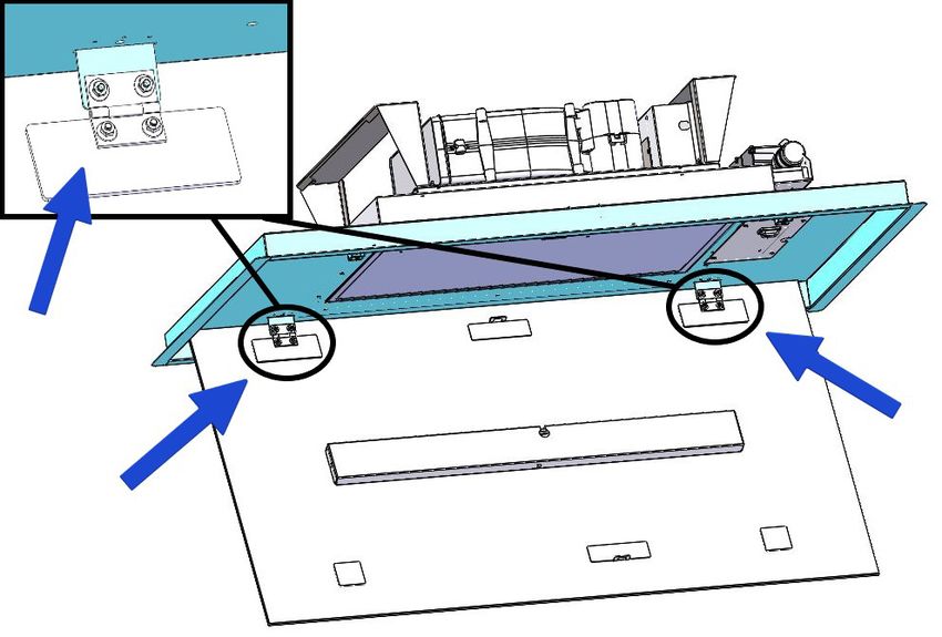
7        8

9        10

11       12
     4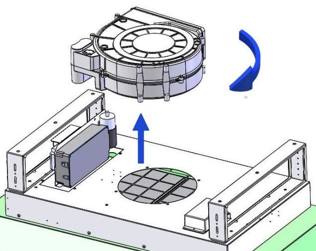
13

14

15       16
     5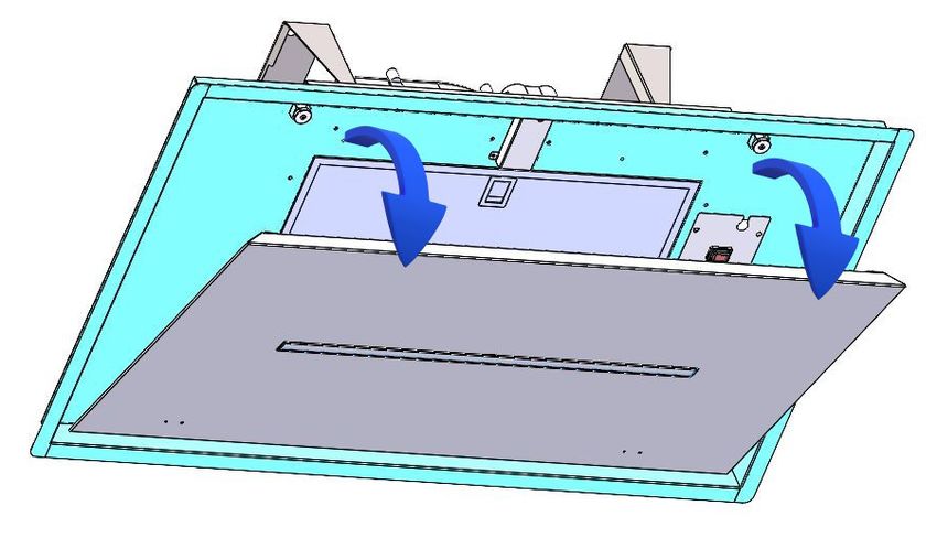
17       18

19       20

21
     6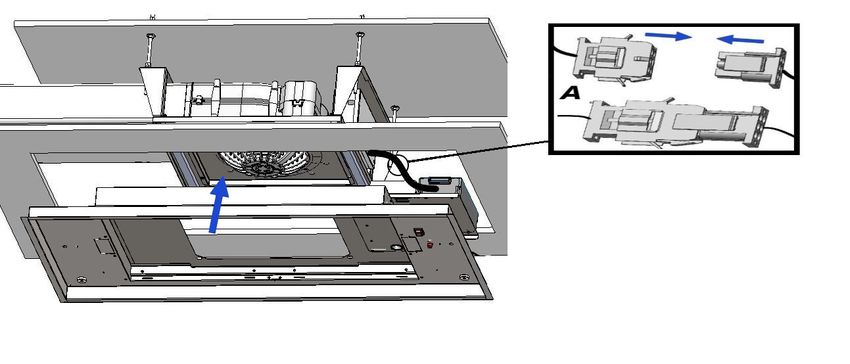
INDICE       IT

Avvertenze

Sistema d’uso

Installazione

Funzionamento

Manutenzione

                         7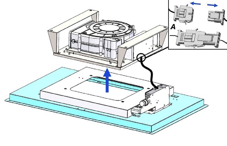
- I bambini non devono giocare
        AVVERTENZE                          con l’apparecchio.

                                            - la pulizia e la manutenzione
L’uscita aria dell’apparecchio, non         non devono essere eseguite da
deve essere collegata ad un con-            bambi ni senza supervisione.
dotto usato per lo scarico di altri
fumi quali impianti di riscaldamen-         - Se il cavo di alimentazione è
to, scaldabagni, ecc..                      danneggiato, esso deve essere
Per l’emissione all’esterno dell’aria       sosti tuito da un cavo o da un as-
rispettare le norme vigenti.                semblaggio speciale, disponibili
                                            presso il costruttore o il suo ser-
L’alimentazione per il motore della         vizio assistenza tecnica.
centralina avviene tramite la cap-
pa posta in cucina.                         - Il locale deve disporre di ade-
Prima del collegamento elettrico            guata ventilazione quando si
assicurarsi che i valori di tensione        utilizza la cappa da cucina con-
dell’abitazione corrispondano con           temporaneamente con altri ap-
quelli delle traghette dati elettrici       parecchi che impiegano gas o
dell’apparecchio.                           altri combustibili (non si applica
                                            agli apparecchi che si limitano a
Prima di procedere a qualsiasi              scaricare nuovamente l’aria nel
tipo di operazione di pulizia o ma-         locale);
nutenzione assicurarsi che l’appa-
recchio sia scollegato dalla rete           - Esiste la possibilità di incendio
elettrica.                                  qualora le operazioni di pulizia
                                            non vengano effettuate secondo
Una buona manutenzione garanti-             quanto indicato nelle istruzioni;
sce un buon funzionamento ed un
buon rendimento nel tempo.                  - Non preparare alimenti flambé
                                            sotto la cappa da cucina.
Tutti i modelli sono in classe I per-
tanto necessitano di collegamento           ATTENZIONE: Le parti accessi-
a terra.                                    bili possono scottare se utilizzate
                                            in concomitanza con gli apparec-
- Questo apparecchio può essere             chi di cottura.
utilizzato da bambini di età pari o
superiore a 8 anni e da persone
con ridotte capacità fisiche, sen-
soriali o mentali o mancanza di
esperienza e conoscenza se sono
stati sottoposti a supervisione o
istruzione sull’uso dell’apparec-
chio in modo sicuro e comprendo-
no pericoli coinvolti.
                                        8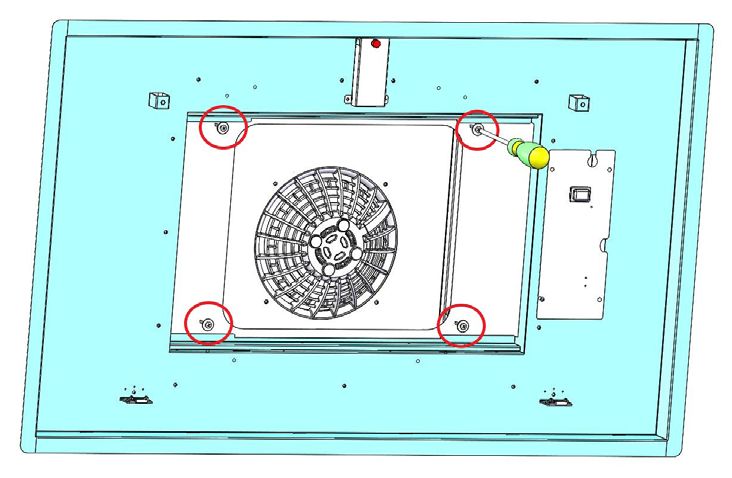
SLT970 BRHM
         VERSIONI D’USO
                                                                         SLT971 BRHM
APERTURA PANNELLI                                            Estrarre il prodotto dalla confezione e collocarlo
E’ possibile aprire i pannelli di copertura dei filtri       su una superficie adatta: suggeriamo di usare un
antigrasso tirandoli delicatamente come indicato             morbido materiale, come una spugna o un pan-
in fig. 1.                                                   no.
                                                             Aprire il pannello ruotandolo come mostrato in
Per un adeguato funzionamento si consiglia di in-            Fig.1 e rimuovere i filtri antigrasso.
stallare il prodotto ad una distanza massima, dal            NEL CASO DI PANNELLO IN VETRO PRIMA
livello del pavimento, di 2000 - 2100 mm.                    DELL’INSTALLAZIONE, PER EVITARE QUAL
                                                             SIASI POSSIBILE DANNO AI VETRI, SI RAC-
Prima di procedere nell’installazione dell’appa-             COMANDA DI RIMUOVERE IL PANNELLO IN
recchio verificare che tutti i componenti non siano          VETRO DALLA CAPPA SVITANDO LE VITI RI-
danneggiati, in caso contrario contattare il riven-          PORTATE IN FIG.2.
ditore e non proseguire con l’installazione.                 Rimuovere i filtri antigrasso (Fig. 3).
Utilizzare un tubo di evacuazione aria che abbia             Svitare le nr.4 viti di fissaggio (Fig. 4), separare la
la lunghezza massima non superiore a 5 metri.                cornice della cappa dalla parte superiore (Fig. 5)
- Limitare il numero di curve nella canalizzazio-            e scollegare il cavo elettrico (Fig. 5A).
ne poiché ogni curva riduce l’efficienza di aspi-            L’ apertura che ospiterà la cappa dovrà essere:
razione equiparata a 1 metro lineare. (Es: se si
utilizzano n°2 curve a 90°, la lunghezza della ca-           850 x 470 per il modello SLT970
nalizzazione non dovrebbe superare i 3 metri di              865X515 per il modello SLT971 Cm90
lunghezza).                                                  1165x615 per il modello SLT971 Cm120.
- Evitare cambiamenti drastici di direzione.
- Utilizzare un condotto con diametro da                     La distanza tra il cartongesso e il soffitto solido
150mm/200mm costante per tutta la lunghezza.                 dovrà essere compresa tra 200 mm a 280 mm.
- Utilizzare un condotto di materiale approvato              Effettuare le quattro forature nel soffitto solido uti-
normativamente.                                              lizzando una punta elicoidale con diametro 8mm,
                                                             seguendo le quote in fig. 6.
                                                             Inserire gli inserti metrici forniti in dotazione, nelle
                                                             forature realizzate.
                                                             Inserire le barre filettate negli inserti metrici pre-
                                                             cedentemente installati.
                                                             Avvitare le barre filettate utilizzando due dadi,
                                                             come da fig. 7, agire nel dado basso per avvitare
                                                             la barra filettata.

                                                             Inserire un ulteriore dado, una rondella metallica
                                                             e la rondella in plastica di bloccaggio come da
                                                             figura 8.
                                                             E’ determinante, ai fini di una corretta installazio-
                                                             ne, posizionare la rondella metallica a 200mm di
                                                             altezza dalla superficie inferiore del cartongesso,
                                                             vedi fig. 9.
                                                             Installare la parte superiore della cappa nello
                                                             scavo in cartongesso realizzato, occorre far coin-
                                                             cidere i 4 fori con le barre filetatte precedente-
                                                             mente installate, come da fig. 10.
                                                             Portare il prodotto a battuta delle rondelle posi-
                                                             zionate in precedenza.
                                                             Bloccare il prodotto mediante 4 rondelle e 4 dadi
                                                             forniti in dotazione. (fig. 11)
                                                             Effettuare il collegamento della canalizzazione
                                                             uscita aria (fig.12).
                                                         9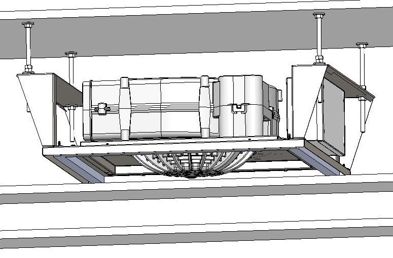
Prendere la cornice della cappa precedentemen-
te smontata e posizionarla al di sotto dell’apertu- SLT958 BRHM
ra ricavata nel cartongesso (fig. 13).
Collegare il cavo motore precedentemente scol- INSTALLAZIONE VERSIONE
legato (fig. 14A) ed il cavo alimentazione rete
elettrica.
BUILT IN - ASPIRANTE
Fissare la cornice alla parte superiore della cap-
pa mediante nr. 4 viti (fig.4). Prelevare il prodotto dall’imballo e posizionarlo
in una zona idonea, si consiglia di utilizzare del
materiale morbido come spugna o panno, su cui
appoggiare il prodotto.
Aprire il pannello ruotandolo come da fig.1,
NEL CASO DI PANNELLO IN VETRO PRIMA
DELL’INSTALLAZIONE, PER EVITARE QUAL-
SIASI POSSIBILE DANNO AI VETRI, SI RAC-
COMANDA DI RIMUOVERE IL PANNELLO IN
VETRO DALLA CAPPA SVITANDO LE VITI RI
PORTATE IN FIG. 2.
Rimuovere i filtri antigrasso (fig. 3).
Si dovrà realizzare una nicchia nella quale in-
stallare il prodotto, detta nicchia deve avere una
apertura di forma rettangolare 865mm x 405
mm per una profondità compresa tra 200mm e
270mm.
LA NICCHIA DEVE ESSERE REALIZZATA A SE
GUITO DELL’INSTALLAZIONE DEL PRODOT
TO E SOPRATTUTTO A SEGUITO DEL COLLE
GAMENTO DELLA TUBATURA USCITA ARIA.
Prevedere nella nicchia una presa di corrente e la
tubatura circolare del diametro di 150mm, o pari
sezione, per l’uscita aria.
Effettuare le forature al soffitto solido come indi-
cato in fig. 17, inserire i tasselli in plastica nei fori
praticati quindi installare le staffe a soffitto come
da fig.18.
Le staffe a soffitto sono telescopiche pertanto,
è possibile avere una regolazione in altezza di
70mm tra il soffitto solido e la cappa.
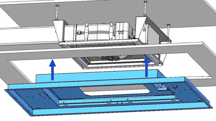
Nel caso si intenda orientare l’uscita aria del
prodotto, in una direzione diversa da quella pre-
stabilita in fabbrica, è possibile smontare il ven
tilatore (vedi fig. 19), agendo sulle quattro viti di
fissaggio, quindi ruotarlo e posizionarlo come si
desidera, ripristinare le quattro viti di fissaggio ri-
mosse in precedenza.
Avvicinare la cappa in corrispondenza delle staffe
installate quindi effettuare il collega mento elet-
trico.
Fissare il prodotto al soffitto mediante le viti, for-
nite in dotazione, come da fig. 20.
10SLT975 BRHM FUNZIONAMENTO
Prelevare il prodotto dall’imballo e posizionarlo RADIOCOMANDO SERIE
in una zona idonea, si consiglia di utilizzare del RC001
materiale morbido come spugna o panno, su cui Radiocomando per il comando a distanza di cap-
appoggiare il prodotto. pe aspiranti.
Aprire il pannello ruotandolo come da fig.1.
Rimuovere i filtri antigrasso (fig. 3). CARATTERISTICHE TECNICHE
Si dovrà realizzare una nicchia nella quale in - Alimentazione pila alkalina: 12V mod. 27A
stallare il prodotto, detta nicchia deve avere una - Frequenza di lavoro: 433,92 Mhz
apertura di forma rettangolare - Combinazioni: 32.768
- Consumo max.: 25 mA
865 x 465 per il modello SLT975 Cm90 - Temperatura d’esercizio: -20 ÷ + 55 °C
1165 x 615 per il modello SLT975 Cm120. - Dimensioni: 130x45x15mm.
per una profondità compresa tra 210mm e DESCRIZIONE DI FUNZIONAMENTO
280mm. Il trasmettitore è dotato di 5 tasti per la gestione
LA NICCHIA DEVE ESSERE REALIZZATA A SE- del funzionamento della cappa, come di seguito
GUITO DELL’INSTALLAZIONE DEL PRODOT- specificato:
TO E SOPRATTUTTO A SEGUITO DEL COLLE-
GAMENTO DELLA TUBATURA USCITA ARIA.
Prevedere nella nicchia una presa di corrente e la : interruttore ON/OFF luce.
tubatura circolare del diametro di 150mm, o pari : interruttore ON (1° velocità) OFF motore.
sezione, per l’uscita aria.
: diminuire velocità.
Effettuare le forature al soffitto solido come indi-
cato in fig. 21, inserire i tasselli in plastica nei fori : aumentare velocità.
praticati quindi installare le staffe a soffitto come : temporizzatore 10 minuti.
da fig.18.
Le staffe a soffitto sono telescopiche pertanto, La velocità di aspirazione impostata viene indica-
è possibile avere una regolazione in altezza di ta mediante il led presente nel canale perimetrale
70mm tra il soffitto solido e la cappa. di aspirazione.
Nel caso si intenda orientare l’uscita aria del Ad ogni colore generato dal led, corrisponde una
prodotto, in una direzione diversa da quella pre determinata velocità come indicato sotto:
stabilita in fabbrica, è possibile smontare il ven- Prima velocità colore BIANCO
tilatore (vedi fig. 19), agendo sulle quattro viti di Seconda velocità colore AZZURRO
fissaggio, quindi ruotarlo e posizionarlo come si Terza velocità colore BLU
desidera, ripristinare le quattro viti di fissaggio ri- Quarta velocità colore ROSSO
mosse in precedenza.
Avvicinare la cappa in corrispondenza delle staffe
installate quindi effettuare il collega mento elet-
trico.
Fissare il prodotto al soffitto mediante le viti, for-
nite in dotazione, come da fig. 20.
11FUNZIONE LUCI DIMMERABILE CONDIZIONE INIZIALE DI FUNZIONAMENTO
Il radiocomando viene fornito dal costruttore
TALE FUNZIONE PREVEDE LA DIMMERA- pronto per l’uso, contenente già dei codici prede-
BILITA’ DELLE LUCI DAL 20% FINO AL 100% finiti di Fabbrica.
TRAMITE LA PRESSIONE CONTINUATA DEL
TASTO LUCE DEL TELECOMANDO.
LE FUNZIONI SONO LE SEGUENTI:
- LUCE CAPPA SPENTA - PRESSIONE BREVE
DEL TASTO - ACCENZIONE LUCE AL 100%.
MODALITÀ DI FUNZIONAMENTO
- LUCE ACCESA AL 100% - PRESSIONE BRE- Configurazione standard:
VE DEL TASTO - SPEGNIMENTO LUCE. La configurazione di fabbrica prevede che tut-
ti i sistemi “ cappa - radiocomando “ abbiano lo
- LUCE ACCESA AL 100% - PRESSIONE CON- stesso codice di trasmissione. Nel caso siano
TINUATA DEL TASTO - DIMINUZIONE DELLA installati due sistemi “ cappa - radiocomando “
LUMINOSITÀ. nello stesso locale o nelle immediate vicinanze
i sistemi avendo lo stesso codice di trasmissione
- RILASCIO DEL TASTO DURANTE LA DIMINU- potrebbero essere influenzati quindi è necessario
ZIONE O INCREMENTO - LA LUCE RIMANE cambiare il codice di un solo radiocomando.
NELL’INTENSITÀ OTTENUTA.
Generazione di un nuovo codice trasmissio-
- LUCE ACCESA DIMMERATA - NUOVA PRES- ne:
SIONE CONTINUATA DEL TASTO - INVERSIONE Il radiocomando viene fornito dalla fabbrica con
LUMINOSITA’ RISPETTO ALLA PRECEDENTE. dei codici predefiniti. Se si desidera una nuova
generazione di codici, occorre eseguire la proce-
dura nel seguente modo: premere contempora-
SETTAGGIO TEMPERATURA COLORE neamente i tasti:
Assicurarsi che le luci ed il ventilatore siano spenti.
Tenendo premuto il tasto TIMER, viene accesa la
luce nella temperatura colore impostata in pre ce- in modo continuo per 2 secondi, nello stesso
denza. istante si avrà l’accensione dei Led, successiva-
Premere e mantenere premuto il tasto Luce per va- mente premere i tasti:
riare la temperatura colore.
Fintanto che il tasto viene mantenuto premuto, vie-
ne variata la temperatura colore da calda a fredda,
basta lasciare il tasto Luce per seleziona re il colore (entro 5 secondi), 3 lampeggi dei Led indicheran-
desiderato. no che l’operazione è stata completata.
Uscire dalla funzione di selezione della tempera
tura colore premendo il tasto ON/OFF. ATTENZIONE! Questa operazione cancella in
maniera definitiva i codici preesistenti.
Apprendimento del nuovo codice di trasmis-
sione:
Dopo aver cambiato il codice di trasmissione nel
radiocomando, occorre far apprendere alla cen-
trale elettronica della cappa aspirante il nuovo
codice nel seguente modo:
Premere il pulsante di spegnimento generale
della cappa (Fig. 15), ripristinare l’alimentazione
alla centrale elettronica, da questo momento ci
sono 15 secondi di tempo per premere il tasto
Luce: per far sì che la centrale si sincronizzi
con il nuovo codice.
12Ripristino della configurazione di Fabbrica: TEMPORIZZAZIONI
Se si desidera ripristinare la configurazione di Con l’entrata in vigore dal 1° Gennaio 2015 dei
Fabbrica, occorre eseguire la procedura nel se- nuovi regolamenti della Commissione Europea
guente modo: premere contemporaneamente i EU65 “Energy label” e EU66 “ Ecodesign”, ab-
tasti: biamo reso conforme i prodotti in base ai requisiti
richiesti.
Tutti i modelli nelle versioni energy label dispon-
gono di una elettronica, con funzioni di temporiz-
in modo continuo per 2 secondi, nello stesso zazione delle velocità di aspirazione, superiore a
istante si avrà l’accensione dei Led, successiva- 650m³/h.
mente premere i tasti: In effetti i modelli con motore a bordo, con porta-
ta massima superiore a 650m³/h, prevedono la
IVa velocità temporizzata dopo 5 minuti di funzio-
namento, Trascorsi i tempi di cui sopra il motore
(entro 5 secondi), 6 lampeggi dei Led indicheran- di aspirazione passa alla IIIa velocità in maniera
no che l’operazione è stata completata. automatica.
ATTENZIONE! Questa operazione cancella in I prodotti in versione external motor, vengono
maniera definitiva i codici preesistenti. abbinati soltanto con motori remoti dove, come
per la versione con motore a bordo, vengono
Tasto d’emergenza: temporizzate le velocità con portate superiori a
In caso di non funzionamento del radiocomando, 650m³/h. (Vedi istruzioni riportate nei motori re-
per lo spegnimento dell’apparecchiatura, interve- moti).
nire sul tasto d’emergenza. Dopo eventuali ripa- I motori remoti, che hanno una portata superio-
razioni, ripristinare il tasto d’emergenza. re a 650m³/h sia alla IVa che alla IIIa velocità,
vengono automaticamente temporizzate come
ATTENZIONE segue: dalla IVa velocità, dopo 6 minuti di funzio-
La batteria deve essere sostituita ogni anno namento passa automaticamente alla II velocità.
per garantire la portata ottimale del trasmet- Se il prodotto viene impostato alla IIIa velocità,
titore. passa automaticamente alla II velocità dopo 7
Per sostituire la batteria scarica rimuovere il minuti. Resta comunque possibile modificare le
coperchio di plastica, togliere la batteria in uso velocità in uso.
e inserirne una nuova rispettando la polarità Il prodotto in modalità stand-by ha un consumo
indicata nel contenitore. inferiore a 0.5W.
La batteria usata deve essere smaltita negli
appositi raccoglitori.
Il prodotto
Radiocomando RC001
è conforme alle specifiche della Direttiva
RED 2014/53/EU.
AVVERTENZE
Cambiamenti o modifiche non espressamente
approvate dal detentore del certificato di com-
patibilità alle norme possono invalidare il di-
ritto dell’utente all’utilizzo dell’apparecchiatura
Rev. 0 26/08/14
Il prodotto è dotato di un dispositivo elettronico
che permette lo spegnimento automatico dopo
quattro ore di funzionamento dall’ultima opera-
zione eseguita.
13MANUTENZIONE
Una manutenzione accurata garantisce un buon
funzionamento e prestazioni durature.
Una speciale cura va rivolta al filtro antigrasso:
per accedere al filtro, procedere come descritto
nel Capitolo APERTURA DEL PANNELLO.
Rimuovere il filtro antigrasso, usando l’apposita
maniglia.
Per rimontare il filtro antigrasso dopo la pulizia,
eseguire
la stessa operazione in ordine inverso.
Per rimuovere il filtro al carbone, se installato, se-
guire gli stessi passi come per il filtro antigrasso.
Il filtro a carbone si trova immediatamente sopra
il filtro antigrasso.
L’acqua tiepida e detergenti neutri sono racco-
mandati per pulire l’apparecchio, mentre devono
essere evitati prodotti abrasivi.
Se il cavo di alimentazione è danneggiato, deve
essere sostituito o dal produttore o da un centro
assistenza assistenza o da una persona qualifi-
cata per evitare rischi.
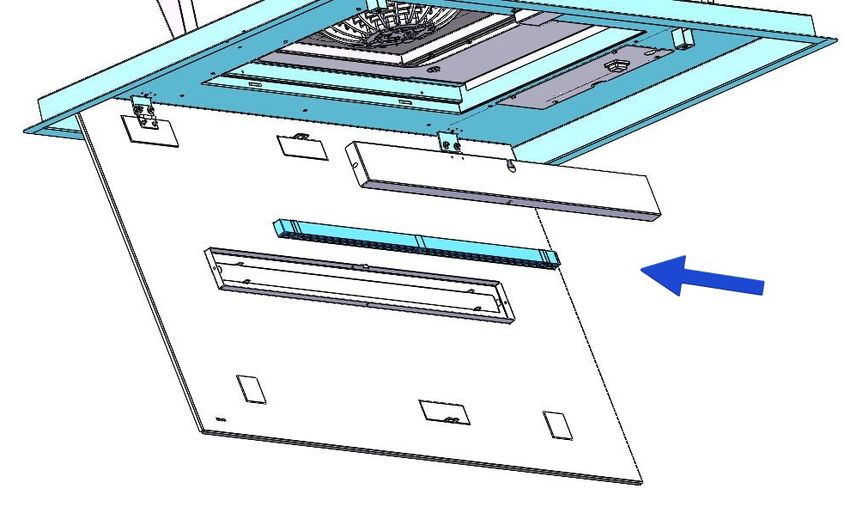
* Sostituzione della barra LED
Utilizzando un utensile appropriato, rimuovere la
barra LED dalla sua sede (vedi Fig. 15), scolle-
garla elettronicamente mediante l’apposito con-
nettore quindi sostituirla con una di pari caratte-
ristiche.
SOSTITUZIONE DELLA BARRA LED PANNELLO
IN VETRO
Per la sostituzione della barra led si consiglia di
rimuovere il listello in metallo come da figura 16.
Sostituire la barra led con una di pare caratteri-
stiche.
Ripristinare il listello metallico al prodotto.
14CONTENTS GB
Warnings
Uses
Installation
Working
Maintenance
15concerning use of the appliance
WARNINGS in a safe way and under stand
the hazards involved.
The air outlet of the appliance - Children shall not play with the
must not be connected to a flue appliance.
which is used for exhausting other
fumes from appliances, such as a - Cleaning and user maintenan-
central heating, boilers etc.. ce shall not be made by children
without supervision.
For the external exhausting of the
fumes, comply with the regula- - If the power cable is damaged,
tions in force. it must be replaced by a cable
or a special assembly, available
The motor of the peripheral from the manufacturer or its ser-
exhausting group is powered by vice de partment technique.
the coo ker-hood placed in the
kitchen. - The room must have adequa-
te ventilation when using the
Before connecting the cooker kitchen hood simultaneously with
hood to the mains supply, make other appliances that use gas or
sure that the voltage indicated in other fuels (not yes applies to
the rating plate corresponds to appliances that simply release
the mains voltage in the home. the air back into the room);
Before carrying out any sort of - There is the possibility of fire if
maintenance or cleaning opera- the cleaning operations are not
tion, make sure that the applian- carried out as indicated in the in-
ce is disconnected from the elec- structions;
trical mains.
- Do not prepare flambéed food
An appropriate maintenance en- under the kitchen hood.
sures a good working and a good
per formance in the long run. ATTENTION: The accessible
parts can burn if used in conjun-
All models are built in class I, the- ction with the cooking applian-
refore they must be earthed. ces.
- This appliance can be used by
children aged from 8 years and
above and persons with reduced
physical, sensory or mental ca-
pabilities or lack of experience
and knowledge if they have been
given supervision or instruction
16SLT970 BRHM
USES
SLT971 BRHM
PANEL OPENING Take the product out of the packaging and place
it on a suitable surface: we Suggest to use a soft
It is possible to open the panel, which cover the material, such as a sponge or a cloth.
grease filters, slightly pulling the panel on a side, Open the glass panel , rotating it as shown in Fig.
as shown on fig. 1. 1.
In order to make the hood working properly, it is IN CASE THE HOOD COMES WITH A GLASS
recommended to install the appliance at a distan- PANEL BEFORE INSTALLATION , IN ORDER
ce of 2000 - 2100 mm from the floor. TO AVOID ANY POSSIBLE DAMAGE TO THE
GLASSES, WE RECOMMEND TO REMOVE
Before starting the appliance installation, please THEM BY UNSCREWING THE EIGHT SCREWS
check that all components are not damaged, in SHOWN IN FIG.2.
such a case contact your retailer and do not carry Remove the grease filters (Fig. 3).
out installation. Unscrew the 4 fixing screws (Fig. 4), separate
Furthermore, please read carefully all of the fol- the hood frame from the upper part (Fig. 5) and
lowing installation instructions. disconnect the electric cable (Fig. 5A).
- Use an exhausting pipe whose maximum length Where you intend to install the appliance, you
does not exceed 5 meters. must create a recess which will have a rectangu-
- Limit the no. of elbows in the piping, since each lar opening of:
elbow reduces the air capacity of 1 linear meter.
(Ex.: if you use no. 2 x 90 ° elbows, the length of 850 x 470 per il modello SLT970
piping must not exceed 3 meters). 865x515 mm model SLT971 Cm.90
- Avoid abrupt direction changes. 1165X615 mm model SLT971 Cm.120
- Use a 150 mm constant diameter pipe for the
whole length, or same section. The depth must range from 200 to 280mm.
- Use piping approved by standards in force.
Make the four holes in the solid ceiling using an
8mm helical bit, following the dimensions in fig.6.
Insert the dowels supplied in the holes made.
Insert the threaded rods in the previously instal-
led dowels.
Screw the threaded rods using two nuts, as
shown in fig. 7, act in the low nut to screw the
threaded rod.
Insert an additional nut and the plastic locking
washer as shown in figure 8.
It is crucial, for a correct installation, to place the
metal washer 200mm high from the bottom surfa
ce of the plasterboard, see fig. 9.
Install the upper part of the hood in the plasterbo
ard niche already made, the 4 holes must coinci
de with the threaded bars previously installed, as
shown in fig. 10.
Bring the product to the stop of the washers pre
viously positioned.
Secure the product with the 4 washers and 4 nuts
supplied. (fig. 11)
Connect the air outlet ducting (fig. 12).
Take the frame of the dismantled hood and
position it under the opening made in the
plasterboard(fig.13).
17Connect the previously disconnected motor cable
(fig.14A) and the power supply cable. SLT958 BRHM
Fasten the frame to the upper part of the hood
using n. 4 screws (fig. 4). BUILT IN - SUCKING VERSION
INSTALLATION
Take the product out of the packaging and place
it on a suitable surface: we suggest to use a soft
ma terial, such as a sponge or a cloth.
Open the glass panel, rotating it as shown in Fig.
1.
IN CASE THE HOOD COMES WITH A GLASS
PANEL BEFORE INSTALLATION , IN ORDER
TO AVOID ANY POSSIBLE DAMAGE TO THE
GLASSES, WE RECOMMEND TO REMOVE
THEM BY UNSCREWING THE EIGHT SCREWS
SHOWN IN FIG.2.
Remove the grease filters (Fig. 3).
A recess shall be created , where the applian-
ce will be placed, which shall have a 865mm X
405mm rectangular opening and depth ran ging
from 200mm to 270 mm.
THE RECESS SHALL BE MADE AFTER IN
STAL LING THE APPLIANCE AND ESPECIALLY
AFTER
CONNECTING THE AIR OUTLET PIPE
The recess shall be provided with a socket and a
round pipe of 150mm diameter, or a similar sec-
tion, for the air outlet.
Drill the holes on the ceiling, as shown in Fig. 17,
in sert the plastic plugs into the holes made, and
then fix the ceiling brackets as shown in Fig. 18.
The ceiling brackets are telescopic, so their
height can be adjusted at 70mm between the cei-
ling and the hood.
If you intend to orient the air outlet of the product,
in a different direction from that established in the
factory, you can dismantle the fan (see fig.19),
acting on the four fixing screws, then rotate and
position it as you want, restore the four fixing
screws removed previously.
Bring the hood close to the brackets previously
fixed and then connect the appliance to the sup-
ply mains.
Secure the hood to the ceiling, by using the
screws supplied, as shown in Fig. 20.
18SLT975 BRHM WORKING
Take the product out of the packaging and place RC001
it on a suitable surface: we suggest to use a soft RADIO CONTROL
material, such as a sponge or a cloth. Radio control used for the remote operation of
Open the glass panel, rotating it as shown in Fig. 1. ducted cooker hoods.
Remove the grease filters (Fig. 3).
A recess shall be created , where the applian ce TECHNICAL DATA
will be placed, which shall have a - Alkaline battery powered: 12V mod. 27A
- Operating frequency: 433.92 Mhz
865 x 465 for model SLT975 Cm90 - Combinations: 32.768
1165 x 615 for model SLT975 Cm120. - Max. consumption: 25 mA
- Operating temperature: -20 ÷ + 55 °C
and depth ranging from 210mm to 280 mm. - Dimensions: 130x45x15 mm.
THE RECESS SHALL BE MADE AFTER IN
STAL LING THE APPLIANCE AND ESPECIALLY OPERATING DESCRIPTION
AFTER CONNECTING THE AIR OUTLET PIPE. The transmitter is equipped with 5 buttons for co-
The recess shall be provided with a socket and a oker hood management, as specified below:
round pipe of 150mm diameter, or a similar sec-
tion, for the air outlet.
Drill the holes on the ceiling, as shown in Fig. 21, : Light ON/OFF command.
in sert the plastic plugs into the holes made, and : Motor ON (speed level 1) / OFF command.
then fix the ceiling brackets as shown in Fig. 18.
: Reduce speed.
The ceiling brackets are telescopic, so their
height can be adjusted at 70mm between the cei- : Increase speed.
ling and the hood. : 10-minute timer.
If you intend to orient the air outlet of the product,
in a different direction from that established in the The set suction speed is indicated by the LED in
factory, you can dismantle the fan (see fig.19), the suction perimeter channel.
acting on the four fixing screws, then rotate and To each color generated by the LED, it corre-
position it as you want, restore the four fixing sponds a specific speed, as shown below:
screws removed previously. First speed WHITE
Bring the hood close to the brackets previously Second speed BLUE
fixed and then connect the appliance to the sup- Third speed DARK BLUE
ply mains. Fourth speed RED
Secure the hood to the ceiling, by using the
screws supplied, as shown in Fig. 20.
19DIMMABLE LIGHTS FUNCTION INITIAL OPERATING CONDITION
The manufacturer supplies the radio control unit
THIS FUNCTION PROVIDES FOR LIGHTS DIM- ready to be used with codes preset in the Factory
MABILITY, RANGING FROM 20% TO 100% , BY
CONTINUOUSLY PRESSING THE LIGHT KEY
ON THE REMOTE CONTROL.
FUNCTIONS ARE THE FOLLOWING:
- HOOD LIGHT OFF - SHORTLY PRESS THE
KEY - LIGHT ON AT 100%. OPERATION MODE
Standard configuration:
- LIGHT ON AT 100% - SHORTLY PRESS THE Standard configuration requires all “cooker hoods
KEY - LIGHT OFF. – radio control - system” to be provided with the
same transmission code. In the event two cooker
- LIGHT ON AT 100% - CONTINOUSLY PRESS hoods – radio control system are installed in the
THE KEY - BRIGHTNESS REDUCTION. same room or nearby, each system may affect
the operation of the another. Therefore, the code
- RELEASING THE KEY DURING REDUCTION of one radio control system must be changed.
OR INCREASE - LIGHT KEEPS THE LUMI-
NOUS INTENSITY REACHED. Generating a new transmission code:
The radio control system is provided with preset
- LIGHT ON - DIMMED - CONTINOUSLY PRESS codes. Should new codes be required, proceed
THE KEY - BRIGHTNESS IS INVERTED IF as follows: Press simultaneously buttons:
COMPARED TO THE PREVIOUS FUNCTION.
COLOUR TEMPERATURE SETTING for two seconds. When Leds light on, press but-
tons:
Make sure that the lights and the fan are off.
Holding down the TIMER key will turn on the light
at the previously set colour temperature.
Press and hold the Light key to change the colour (within 5 seconds). Leds flashing 3 times indicate
temperature. the procedure is completed.
As long as the key is kept pressed, the colour
temperature is changed from warm to cold, just WARNING! This operation deletes permanen-
leave the Light key to select the desired colour. tly the preset codes.
Exit the colour temperature selection function by
pressing the ON/OFF key. Learning the new transmission code:
Once the transmission code is changed in the ra-
dio control unit, the electronic central unit of the
cooker hood must be made to set the new code
in the fol- lowing way:
Press the main power-off button (fig. 15) of the
hood and then restore power to the electronic
control unit. Within the next 15 seconds, press
the Liight Button to synchronise the central
unit with the code.
Reset of the Factory configuration:
To restore the Factory configuration, follow the
procedure described below: press simultaneou-
sly buttons:
20for 2 seconds. When Leds light on, press buttons:
MAINTENANCE
(within 5 seconds). Leds flashing 6 times indicate
the procedure is completed. An accurate maintenance guarantees good fun-
WARNING! This operation deletes permanen- ctioning and long-lasting performance. Special
tly the preset codes. care needs to be taken with the grease filter:
to access the filter, proceed as described in the
Emergency button: PANEL OPENING chapter.
In the event that the radio control does not work, Remove the grease filter, using the special handle.
use the emergency button to switch the appliance To refit the grease filter after cleaning, carry out
off. After any necessary repairs have been perfor- the same operation in reverse order.
med, reset the emergency button. To remove the carbon filter, if fitted, follow the
same steps as for the grease filter.
WARNING The carbon filter is located immediately above
The battery should be replaced every year to the grease filter.
guarantee the optimal range of the transmitter. Tepid water and neutral detergents are recom-
To replace the exhausted battery, take the pla- mended to clean the appliance, while abrasive
stic lid off, remove the battery and replace it products should be avoided.
with a new one, observing the correct battery
polarities. If the supply cord is damaged, it must be replaced
Used batteries should be discarded in special by the manufacturer or its service agent or a simi-
collection bins. larly qualified person in order to avoid a hazard.
* Replacement of the LED bar:
The below product: Using an appropriate tool, remove the LED bar
RC001 Radio Controll from its seat (refer to Fig. 15), disconnect it elec-
complies with the specifications set out in the tro nically throught the appropriate connector
Directive RED 2014/53/EU. then re place it with a LED bar with same cha-
racteristics.
WARNING * Replacement of the LED bar GLASS PANEL
Any adjustments or modifications which have To remove the led bar , it is recommended to re-
not been expressly approved by the holder of move the steel bar as shown in Fig. 16.
the legal conformity certificate may invalidate Replace the led bar with one of the same cha-
the user’s rights relating to the operation of racteristics.
the device. Refit the steel bar.
Rev. 0 26/08/14
The products are endowed with an electronic de-
vice which allows the automatic switching off after
4 hours working from the last operation.
2122
IT   Il simbolo sul prodotto o sulla confezione indica che il prodotto non deve essere considerato
     come un normale rifiuto domestico, ma deve essere portato nel punto di raccolta appro-
     priato per il riciclaggio di apparecchiature elettriche ed elettroniche. Provvedendo a smal-
     tire questo prodotto in modo appropriato, si contribuisce a evitare potenziali conseguenze
     negative per l’ambiente e per la salute, che potrebbero derivare da uno smaltimento ina-
     deguato del prodotto. Per informazioni più dettagliate sul riciclaggio di questo prodotto,
     contattare l’ufficio comunale, il servizio locale di smaltimento rifiuti o il negozio in cui è sta-
     to acquistato il prodotto. Questo elettrodomestico è marcato conformemente alla Diretti-
     va Europea 2012/19/EC sui rifiuti da apparecchiature elettriche ed elettroniche (WEEE).

GB   The symbol on the product or on its packaging indicates that this product may not be
     treated as household waste. Instead it shall be handed over to the applicable collec-
     tion point for the recycling of electrical and electronic equipment. By ensuring this pro-
     duct is disposed of correctly, you will help prevent potential negative consequences for
     the environment and human health, which could otherwise be caused by inappropriate
     waste handling of this product. For more detailed information about recycling of this pro-
     duct, please contact your local city office, your household waste disposal service or the
     shop where you purchased the product. This appliance is marked according to the Eu-
     ropean directive 2012/19/EC on waste electrical and electronic equipment (WEEE).

                                               23
90007011099 - 01/21
Puoi anche leggere