Atisa Aero-Termica Italiana S.p.A - SSV MANUALE D'USO USER MANUAL
←
→
Trascrizione del contenuto della pagina
Se il tuo browser non visualizza correttamente la pagina, ti preghiamo di leggere il contenuto della pagina quaggiù
Atisa Aero-Termica Italiana S.p.A.

                MANUALE D’USO
                 USER MANUAL

                    SSV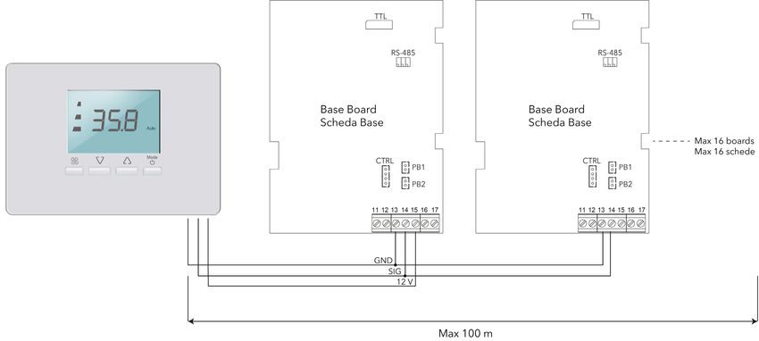
ATTENZIONE:                                                                  CAUTION:
     PRIMA D’INSTALLARE L’APPARECCHIO LEGGERE                                          BEFORE INSTALLING THE DEVICE,
          ATTENTAMENTE QUESTO MANUALE.                                              PLEASE READ THIS MANUAL CAREFULLY.

             LETTERA ALLA CONSEGNA                                                         LETTER AT DELIVERY
Gentile cliente, queste unità sono state costruite in conformità alle     Dear Customer, these units are constructed in compliance with
Direttive 2006/42/EC (Direttiva macchine), 2006/95/EC (Direttiva          Directives 2006/42/EC (Machines Directive), 2006/95/EC (Low
bassa tensione), 2004/108/EC (Compatibilità elettromagnetica) ed          Voltage Directive), 2004/108/EC (Electromagnetic Compatibility)
alla 2002/95/EC (RoHS).                                                   and 2002/95/EC (RoHS).
Le prevenzioni dettate dalle normative vigenti devono comunque            The measures set out by current regulations must nevertheless
essere adottate dal costruttore, dall’installatore e dal proprietario     be observed by the Manufacturer, the installer and the owner of
della macchina per le parti di competenza.                                the machine for the relevant parts.
Atisa, in qualità di costruttore, interpreta l’applicazione della         Atisa, as the Manufacturer, plays its part in the application of the
Direttiva Macchine con le prevenzioni che seguono, demandando             Machines Directive with the steps below, requiring the installer -
all’installatore, o al proprietario, il completamento della messa in      or owner - to complete the safety measures for the machine and
sicurezza della macchina e dell’intero impianto in cui la stessa è        for the entire system in which it is installed.
inserita.                                                                 The device does not present any danger for the operator if used in
L’apparecchio non presenta pericoli per l’operatore se usato              accordance with the safety measures listed later in this manual.
secondo le prescrizioni di sicurezza riportate di seguito in questo       This page is intended to verify that the User manual was delivered
manuale.                                                                  on receipt of the machine, and that the operator assumes all
Questa pagina ha lo scopo di attestare che al ricevimento della           responsibility for following the instructions contained within it.
macchina sia stato consegnato il Manuale d’Uso e che l’operatore
si assuma la responsabilità di seguirlo in ogni sua parte.
                                                                          This manual must also be kept for future reference and Atisa
Questo manuale deve essere inoltre conservato per futuri                  declines all responsibility if the information contained herein is not
riferimenti e Atisa declina ogni responsabilità nel caso non siano        observed.
osservate le raccomandazioni riportate in questo manuale.                 Any damages caused to people, animals or possessions as a
I danni che tali inadempienze possono recare a persone, animali           result of the non-observance of this information is not the
o cose non sono a carico della Società.                                   responsibility of the Company.

Atisa si augura che il prodotto possa incontrare piena
soddisfazione e la invitiamo a rivolgersi al nostro Agente di zona        Atisa hopes that you are fully satisfied with this product; please
per qualsiasi ulteriore chiarimento si rendesse necessario.               contact our local Agent if you require any further clarification.
Questo manuale e di proprietà di Atisa e qualsiasi riproduzione           This manual remains the property of Atisa and any duplication,
anche parziale è vietata.                                                 even partial, is strictly prohibited.
Il seguente manuale adotta al suo interno alcuni segni                    This manual contains several conventional symbols that will help
convenzionali che aiutano a meglio identificare i punti ritenuti          you identify essential information.
essenziali.                                                               For this reason we have provided an explanation of the symbols
A tale scopo si da di seguito spiegazione dei simboli utilizzati:         used below:

                          ATTENZIONE:                                                                  CAUTION:
  IGNORARE QUESTA NOTA PUÒ GENERARE UN GUASTO                                 DISREGARDING THIS NOTE MAY CAUSE THE APPLIANCE
    DELL’APPARECCHIO O IL SUO DANNEGGIAMENTO.                                       TO BREAK DOWN OR BECOME DAMAGED.

                               NOTA:                                                                     NOTE:
indica un’informazione importante o di particolare interesse.                  indicates important or particularly relevant information.

                                                                        -2-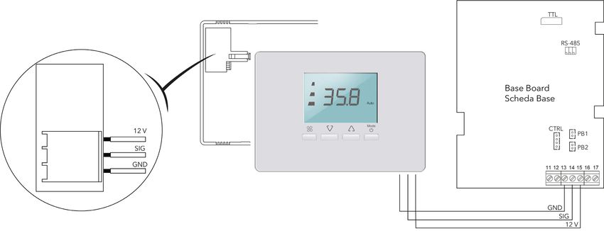
DESCRIZIONE DEL SISTEMA                                                         SYSTEM DESCRIPTION
I principali componenti del sistema di regolazione SSV sono i               The main components of the SSV regulation system are:
seguenti:                                                                   Electronics board:
Scheda elettronica:                                                         the main control part of the SSV system. Normally located on
costituisce la parte di controllo principale del sistema SSV, è             board the unit subject to its control.
normalmente posizionata a bordo dell’unità che è oggetto della              Air - water probes:
regolazione.
                                                                            elements controlling the temperature of the surrounding
Sonde aria - acqua:                                                         environment and the exchange fluids, on which the regulation
sono gli elementi di controllo della temperatura ambiente e dei             modes are based.
fluidi di scambio su cui si basano le modalità di regolazione.              RS485 board:
Scheda RS485:                                                               the board involved in communication from the base board (and
è la scheda che si occupa della comunicazione, tramite protocollo           therefore from the unit) to a remote management system, using
bus, dalla scheda base, quindi dall’unità, ad un sistema remoto di          bus protocol.
gestione.                                                                   Remote Terminal:
Terminale Remoto:                                                           the user interface which connects via cable to the base board and
è l’interfaccia utente che si collega via cavo alla scheda base e           allows the management and programming of that board, and
permette sia la gestione che la programmazione della scheda                 therefore the unit it controls.
stessa e quindi dell’unità che è oggetto della regolazione.                 Remote control:
Telecomando:                                                                the user interface which connects to the base board wirelessly
è l’interfaccia utente che si collega, in modalità wireless ad              using infrared technology, only allowing the management of that
infrarossi, alla scheda base e permette la sola gestione della              board and therefore the unit it controls.
scheda stessa e quindi dell’unità che è oggetto della regolazione.          Infrared receiver:
Ricevitore ad infrarossi:                                                   this module allows wireless exchanging between the remote
è il modulo che permette lo scambio wireless tra il telecomando e           control and the base board on the unit.
la scheda base a bordo dell’unità.

     TRASPORTO E NOTE GENERALI ALLA                                             TRANSPORTATION AND GENERAL NOTES
               CONSEGNA                                                                   ON DELIVERY
Il sistema è contenuto in una o più scatole di cartone e, nel caso          The system is packaged in one or more cardboard boxes and, if
di quantità elevate, può essere posizionato su pallet.                      there are a lot of boxes, may be stacked on pallets.
Al ricevimento della fornitura controllare che:                             On receipt of the products, make sure that:
- l’imballo sia integro.                                                    - the packaging is intact.
- la fornitura corrisponda alle specifiche dell’ordine (vedi bolla di       - the goods supplied correspond to the order specifications (see
consegna).                                                                  delivery note).
- non vi siano danni alle apparecchiature.                                  - the equipment is not damaged.
In caso di danni o di non corrispondenza della fornitura con                If you notice any damage, or if the goods supplied do not match
quanto ordinato, informare immediatamente e in modo dettagliato             the order you placed, please inform the courier and/or ATISA
lo spedizioniere e/o ATISA citando i riferimenti dell’ordine.               immediately, quoting the order reference number.

        STOCCAGGIO E MOVIMENTAZIONE                                                        STORAGE AND HANDLING

                              ATTENZIONE:                                                                CAUTION:
 PER PESI SUPERIORI A 25 KG, PER GLI UOMINI, E 20 KG,                           PACKAGES WEIGHING OVER 25 KG (FOR MEN) AND 20 KG
 PER LE DONNE, SOLLEVARE L’IMBALLO CON L’AIUTO DI                                  (FOR WOMEN) SHOULD BE LIFTED BY 2 PEOPLE.
                UN’ALTRA PERSONA.
                                                                            When the goods arrive, make sure there is a space for them
All’arrivo della fornitura, predisporre uno spazio adeguato che             where:
abbia:                                                                      - they can be placed on a stable surface.
- un piano d’appoggio stabile.                                              - the surrounding environment       is   dry   and   sheltered   from
- un ambiente non umido e riparato dagli agenti atmosferici.                atmospheric agents.

Scaricare la fornitura prestando attenzione alle indicazioni di peso        Unload the goods, noting the weight indications provided on the
riportate sulla bolla e, nel caso, sollevare il carico con l’ausilio di     note and, if necessary, lift the load using suitable equipment such
attrezzi quali transpallet, muletti, ecc..                                  as pallet trucks, forklift trucks, etc.
Le condizioni di stoccaggio sono:                                           The storage conditions are as follows:
Temperatura       =        –30 ÷ +85 °C                                     Temperature      =    -30 ‐ +85°C
Umidità           =        10 ÷ 90 % RH (non condensante).                  Humidity         =    10 ‐ 90% RH (non-condensing).
                                                                          -3-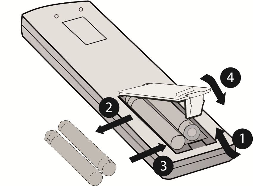
AVVERTENZE GENERALI                                                          GENERAL WARNINGS
I componenti del presente manuale sono stati progettati per la             The components in this manual are designed to regulate
regolazione di ambienti attraverso un insieme di macchine ad               environments by means of an assembly of water-powered
acqua. Atisa declina ogni responsabilità per i danni derivanti da          machines. Atisa declines all responsibility resulting from the
un uso improprio, da una cattiva installazione, da modifiche o da          improper use or incorrect installation of, modifications to or
manomissioni dell’apparecchio.                                             tampering with the device.

Questo libretto deve sempre accompagnare l’apparecchio in                  This manual should be considered an integral part of the device
quanto parte integrante dello stesso.                                      and as such must always be kept with it.
Ogni riparazione o manutenzione deve essere sempre eseguita                Any repair or maintenance work must always be carried out by
da personale qualificato.                                                  qualified staff.

In generale è vietato:                                                     In general the following is prohibited:
- l’uso delle apparecchiature da parte di bambini o da persone             - use of the equipment by children or disabled persons without
   inabili senza assistenza.                                                 assistance.
- toccare le apparecchiature con parti del corpo bagnate o a piedi         - touching the equipment with wet parts of the body, or while
   nudi.                                                                     barefoot.
- qualsiasi tipo d’intervento o manutenzione senza aver prima              - any type of work or maintenance              without   first   having
  scollegato l’alimentazione elettrica.                                      disconnected the electricity supply.
- qualsiasi tipo d’intervento o manutenzione senza aver chiuso             - any type of work or maintenance without having shut off the
  la/e valvola/e di alimentazione dell’acqua e la batteria sia a             water supply valve(s) and ensuring the battery is at room
  temperatura ambiente.                                                      temperature.
- manomettere o modificare i dispositivi di regolazione o di               - tampering with or modifying the regulation or safety devices
  sicurezza senza essere autorizzati e senza indicazioni scritte             without authorisation and without written instructions from Atisa.
  da parte di Atisa.                                                       - twisting, pulling or disconnecting the equipment electrical wires.
- torcere, tirare o staccare i cavi elettrici delle apparecchiature.       - dumping and/or spraying water or other liquids onto the
- gettare e/o spruzzare acqua, o altri liquidi, sulle apparecchiature.       equipment.
- rimuovere qualsiasi elemento di protezione senza aver prima              - removing any protective element             without    first   having
  scollegato l’alimentazione elettrica.                                      disconnected the electricity supply.
- lasciare l’imballo o parte di esso alla portata dei bambini perché       - leaving the packaging, or part of it, within reach of children, as it
   potenziale causa di pericolo.                                             is a potential hazard.
- installare l’apparecchio in atmosfera esplosiva o corrosiva, in          - installing the appliance in an explosive or corrosive environment,
  luoghi molto umidi, molto polverosi o all’aperto.                          in very damp or dusty sites or in the open.

In generale osservare le seguenti prescrizioni:                            The following guidelines in general should be observed:
- conservare le apparecchiature nell’imballo conduttivo di                 - keep the equipment in the protective packaging until ready for
  protezione fino a quando non si è pronti per l’installazione.              installation.
- installare le apparecchiature solo in involucri omologati e/o in         - install the equipment in type-approved casings and/or in points
   punti che impediscano l’accesso casuale e offrano protezione              that prevent accidental access and provide protection from
   contro le scariche elettrostatiche come definito nella IEC 1000-          electrostatic discharge as defined in IEC 1000-4-2.
   4-2.                                                                    - when handling sensitive equipment, use an antistatic bracelet or
- nel maneggiare le apparecchiature sensibili utilizzare un                  equivalent earthed protective device against electrostatic
  braccialetto antistatico o un equivalente dispositivo di                   discharge.
  protezione dalle scariche elettrostatiche collegato a una messa          - before handling the equipment, always discharge the static
  a terra.                                                                   electricity from the body by touching an earthed surface or type-
- prima di maneggiare l’apparecchiatura, scaricare sempre                    approved antistatic mat.
  l’elettricità statica dal corpo toccando una superficie messa a
  terra o un tappetino antistatico omologato.
                                                                           Failure to follow these instructions can result in damage to
                                                                           possessions, serious injury, and/or equipment damage.
Il mancato rispetto di queste istruzioni può essere dannoso per
cose e persone con gravi infortuni e/o danni alle apparecchiature.
                                                                           When replacing components, only use authentic spare parts.

In caso di sostituzione di componenti utilizzare esclusivamente
ricambi originali.

                                                                         -4-
SCHEDA ELETTRONICA                                                       ELECTRONICS BOARD

                            ATTENZIONE:                                                                 CAUTION:
       OSSERVARE TUTTE LE PRECAUZIONI NELLA                                   TAKE ALL THE APPROPRIATE PRECAUTIONS WHEN
      MANIPOLAZIONE DI DISPOSITIVI SENSIBILI ALLE                               HANDLING DEVICES WHICH ARE SENSITIVE TO
            SCARICHE ELETTROSTATICHE.                                                 ELECTROSTATIC DISCHARGES.
La scheda elettronica è sensibile alle scariche elettrostatiche          The electronics board is sensitive to electrostatic discharges and
pertanto occorre eliminare ogni possibile scarica elettrostatica in      therefore all potential electrostatic charge must be eliminated in an
maniera appropriata. Utilizzare braccialetti antistatici, scarpe ed      appropriate manner. Use anti-static bracelets, shoes and suitable
indumenti adeguati, tappetini antistatici, ecc., prima di manipolare     garments, anti-static mats, etc. before handling and installing the
e installare il dispositivo elettronico.                                 electronic device.
La scheda elettronica è del tipo a micro processore ed è protetta        The electronics board has a microprocessor and is protected on
sull’alimentazione da un varistore.                                      the power supply by a varistor.
Tutti i collegamenti a 230Vac sono con morsetto a vite.                  All 230 Vac connections have screw terminals.
Tutti i collegamenti delle sonde sono con innesto rapido.                All probe connections are click-fit.

Dati tecnici (EN 60730-2-9):                                             Technical specifications (EN 60730-2-9):
Classificazione: Dispositivo di funzionamento (non di sicurezza)         Classification: Operating device (not safety device) to be
da incorporare.                                                          incorporated.
Montaggio: Incorporato.                                                  Installation: Built-in.
Tipo di azione: 1.B.                                                     Type of action: 1.B.
Grado di inquinamento: 2.                                                Pollution class: 2.
Gruppo del materiale d’isolamento: IIIa.                                 Insulating material group: IIIa.
Categoria di sovratensione: II.                                          Over-voltage category: II.
Tensione impulsiva nominale: 2500 V.                                     Nominal pulse voltage: 2500 V.
Temperatura:                                                             Temperature:
     Utilizzo: –5 ÷ +55 °C.                                                    Operation: -5 ‐ +55°C.
     Immagazzinamento: –30 ÷ +85 °C.                                           Storage: -30 ‐ +85°C.
Alimentazione: 100 ÷ 240 Vac (±10 %) 50/60 Hz.                           Power supply: 100 ‐ 240 Vac (±10%) 50/60 Hz.
Consumo: 3,5 W max.                                                      Power consumption: 3.5 W max.
Uscite digitali (relè): 5 relè (Vedi “Caratteristiche Uscite”).          Digital outputs (relay): 5 relays (see “Output characteristics”).
Classe del software: A.                                                  Software class: A.

Caratteristiche Ingressi:                                                Input Characteristics:
Accuratezza: NTC: ±0.5 °C per temperature comprese tra -10 ...
+90 °C.                                                                  Accuracy: NTC: ±0.5°C in temperatures between -10        … 90°C.
Risoluzione: 0,1 °C.                                                     Resolution: 0.1°C.
Ingressi Analogici: 2 NTC 10 kOhm @ 25 °C.                               Analogue Inputs: 2 NTC 10 kOhm @ 25°C.
Ingressi Digitali: 1 libero da tensione.                                 Digital Inputs: 1 voltage-free.

Caratteristiche Uscite:                                                  Output Characteristics:
Uscite Digitali:                                                         Digital Outputs:
Bassa velocità ventilatore: 4(2) A.                                      Low fan speed: 4(2) A.
Media velocità ventilatore: 4(2) A.                                      Medium fan speed: 4(2) A.
Alta velocità ventilatore: 4(2) A.                                       High fan speed: 4(2) A.
Uscita Out1: 4(2) A.                                                     Output Out1: 4(2) A.
Uscita Out2: 4(2) A.                                                     Output Out2: 4(2) A.
Uscita Analogica: 1 da 0 a 10 V 1 % del valore di fondo scala.           Analogue output: 1 x 0 to 10 V 1% of the fullscale value.

Caratteristiche Meccaniche:                                              Mechanical Characteristics:
Contenitore: Scheda base fornita a “giorno”.                             Casing: The base board is supplied with no cover.
Dimensioni: 121 x 90 mm.                                                 Dimensions: 121 x 90 mm.

                                                                       -5-
Morsetti: Terminals:
A vite sconnettibili. Quick disconnect screw type.
Connettori: Connectors:
TTL (non utilizzato). TTL (not used).
CTRL (non utilizzato). CTRL (not used).
Pb1 sonda aria Pb1 air probe
Pb2 sonda acqua Pb2 water probe
RS485 modulo di comunicazione RS485 RS485 communication module RS485
Umidità: Utilizzo / Immagazzinamento: 10 ÷ 90 % RH (non Humidity: Operation / Storage: 10 ‐ 90% RH (non-condensing).
condensante).
NOTE:
NOTA:
the technical specifications listed in this document regarding
le caratteristiche tecniche, riportate nel presente documento, measurement (accuracy, resolution, etc.) refer strictly to the
inerenti la misura (accuratezza, risoluzione, ecc.) si instrument and not to any accessories provided, such as the
riferiscono allo strumento in senso stretto, e non ad probes.
eventuali accessori in dotazione quali, ad esempio, le sonde.
TTL
RS485
123
ON
COMUNE
COMMON
M CTRL PB1
PB2
G/V
SUPPLY
M G/V
0 230 D.I. 10V
0V
VA1 VA2
TR
0 230
-6-Collegamenti elettrici: Electrical connections:
terminali [5-6] -Supply = alimentazione scheda 230 Vac. terminals [5-6] -Supply = board power supply 230 Vac.
terminali [11-12] -D.I = ingresso digitale D.I.. terminals [11-12] -D.I. = digital input D.I..
terminali [13–14– 15] -TR = collegamenti del Terminale Remoto. terminals [13–14–15] -TR = Remote Terminal connections.
13 = collegamento di massa (GND). 13 = earth (ground) connection (GND).
14 = collegamento del segnale. 14 = signal connection.
15 = collegamento di alimentazione (+12V). 15 = power supply connection (+12V).
Terminali [16 – 17] = Uscita analogica 0-10V. Terminals [16 – 17] = Analogue output 0-10V.
RS485 = collegamento del modulo RS485. RS485 = RS485 module connection.
CTRL = non utilizzato. CTRL = not used.
Pb1 = connessione rapida sonda aria. Pb1 = air probe quick connection.
Pb2 = connessione rapida sonda acqua. Pb2 = water probe quick connection.
Terminali [1-2-3-4] connessione motore Terminals [1-2-3-4] motor connection
1 = rirono comune 1 = common return
2 = Uscita relé (velocità massima). 2 = Relay output (maximum speed).
3 = Uscita relé (velocità media) 3 = Relay output (medium speed).
4. = Uscita relé (velocità media) 4 = Relay output (medium speed)
[7-8] Out1 e [9-10] (Out2) = Uscite valvole. [7-8] Out1 and [9-10] (Out2) = Valve outputs.
Impianto 2 tubi: 2-pipe systems:
Out1 = Uscita valvola 1 (caldo/freddo). Out1 = Valve 1 output (hot/cold).
Out2 = Non utilizzato. Out2 = Not used.
Impianto 4 tubi: 4-pipe systems:
Out1 = Uscita valvola 1 (caldo). Out1 = Valve 1 output (hot).
Out2 = Uscita valvola 2 (freddo). Out2 = Valve 2 output (cold).
Impianto 2 tubi con resistenza: 2-pipe system with heater:
Out1 = Uscita valvola 1 (caldo/freddo). Out1 = Valve 1 output (hot/cold).
Out2 = Uscita resistenza elettrica. Out2 = Electric heater output.
NOTA: NOTE:
la resistenza elettrica può essere utilizzata come sostituzione the electric heater may be used as a replacement or a
oppure come integrazione in base al parametro di supplement depending on configuration parameter P07
configurazione P07 (vedi sezione ELENCO PARAMETRI). (see LIST OF PARAMETERS section).
TTL = non utilizzato. TTL = not used.
Sulla scheda è presente un led rosso di segnalazione con le There is a red alert LED on the board, which functions as follows:
seguenti funzioni: lit = electronics board powered.
acceso = scheda elettronica alimentata. flashing = Pb2 water probe disconnected or faulty.
lampeggiante = sonda acqua Pb2 scollegata o guasta.
COLLEGAMENTI ELETTRICI ELECTRICAL CONNECTIONS
ATTENZIONE: CAUTION:
NEL CASO DI UTILIZZO CON VENTILATORI BRUSHLESS E IF USING WITH BRUSHLESS FANS, IT IS PROHIBITED TO
VIETATO DERIVARE L’ALIMENTAZIONE DEL DRIVER DEL BRANCH THE FAN DRIVER POWER SUPPLY FROM THE
VENTILATORE, DAI MORSETTI SUPPLY DELLA SCHEDA. BOARD SUPPLY TERMINALS. THE FAN DRIVER MUST
L’ALIMENTAZIONE DEL DRIVER DEL VENTILATORE DEVE ALWAYS BE POWERED DIRECTLY FROM THE MAINS
ESSERE SEMPRE ALIMENTATO DIRETTAMENTE DALLA NETWORK.
RETE.
-7-Configurazione degli Switch. Switch configuration.
Gli Switch presenti sulla scheda permettono di selezionare il The Switches on the board allow selection of the system operating
modo di funzionamento dell’impianto, se di tipo a 2 o 4 tubi, e la mode, whether it has 2 or 4 pipes, and if there are valves and/or an
presenza o meno delle valvole e/o della resistenza elettrica. electric heater.
NOTA: NOTE:
la configurazione dell’unità avviene utilizzando solo gli the unit is only configured using Switches 1 and 2. Switch 3 is
Switch 1 e 2. Lo Switch n° 3 serve per impostare la priorità used to set the priority of the digital input to either local
dell’ingresso digitale da funzionamento locale, dove ogni operation, where each board uses its own, or shared
scheda utilizza il proprio, a funzionamento condiviso, dove operation, where one board also controls the others.
una scheda comanda anche le altre. For a complete explanation of switch 3, please refer to the
Per la spiegazione completa dello switch 3 vedere il paragraph “Switch 3 configuration”.
paragrafo “Configurazione switch 3”.
TTL
ON
RS485
123
123
ON
COMUNE
COMMON
M CTRL PB1
PB2
G/V
SUPPLY
M G/V
0 230 D.I. 10V
0V
VA1 VA2
TR
0 230
Selezione del tipo di impianto: Select system type:
Gli Switch servono ad impostare il tipo di impianto e quindi il tipo The Switches are used to set the system type and therefore the
di funzionamento desiderato. desired type of operation.
La sequenza di configurazione è secondo il seguente schema: The configuration sequence takes place in accordance with the
diagram below:
Posizione di fabbrica: Factory position:
ON Switch 1 = OFF ON Switch 1 = OFF
Switch 2 = OFF Switch 2 = OFF
123 Switch 3 = OFF 123 Switch 3 = OFF
Impianto 2 tubi senza valvole: 2-Pipe system without valves:
ON Switch 1 = OFF ON Switch 1 = OFF
Switch 2 = OFF Switch 2 = OFF
123 Switch 3 = OFF 123 Switch 3 = OFF
-8-Impianto 2 tubi con valvola: 2-Pipe system with valve:
ON Switch 1 = ON ON Switch 1 = ON
Switch 2 = OFF Switch 2 = OFF
123 Switch 3 = OFF 123 Switch 3 = OFF
Impianto 2 tubi con resistenza: 2-pipe system with heater:
ON Switch 1 = ON ON Switch 1 = ON
Switch 2 = ON Switch 2 = ON
123 Switch 3 = OFF 123 Switch 3 = OFF
Impianto 4 tubi con valvole: 4-Pipe system with valves:
ON Switch 1 = OFF ON Switch 1 = OFF
Switch 2 = ON Switch 2 = ON
123 Switch 3 = OFF 123 Switch 3 = OFF
Collegamento delle valvole: Valve connection:
Per il collegamento delle valvole utilizzare il morsetto Out1 per To connect the valves, use terminal Out1 to connect the hot valve
collegare la valvola calda ed il morsetto Out2 per collegare la and terminal Out2 to connect the cold valve.
valvola fredda. The Out2 output can also be used to control an electric heater
E’ possibile utilizzare l’uscita Out2 anche per pilotare una whose operation is defined by parameter P07, as specified in the
resistenza elettrica il cui funzionamento è definito dal parametro LIST OF PARAMETERS section.
P07 come riportato nella sezione ELENCO PARAMETRI. In the diagram, the valves are labelled as:
Nello schema le valvole sono indicate come: 2-pipe systems:
Impianto 2 tubi: Out1 = Valve 1 output (hot/cold).
Out1 = Uscita valvola 1 (caldo/freddo). Out2 = Not used.
Out2 = Non utilizzato. 4-pipe systems:
Impianto 4 tubi: Out1 = Valve 1 output (hot).
Out1 = Uscita valvola 1 (caldo). Out2 = Valve 2 output (cold).
Out2 = Uscita valvola 2 (freddo). 2-pipe system with heater:
Impianto 2 tubi con resistenza: Out1 = Valve 1 output (hot/cold).
Out1 = Uscita valvola 1 (caldo/freddo). Out2 = Heater output.
Out2 = Uscita resistenza.
Probe connection:
Collegamento delle sonde: NTC probes are used and must exclusively be the type specified
Le sonde utilizzate sono del tipo NTC e devono essere solo ed by Atisa.
esclusivamente del tipo previsto da Atisa. Pb1 Recovery air probe.
Pb1 Sonda aria di ripresa. Pb2 Water probe.
Pb2 Sonda acqua.
Remote Terminal connection:
Collegamento del Terminale Remoto: The Remote Terminal allows board configuration and
Il Terminale Remoto permette la configurazione e la gestione management, and consequently board operation.
della scheda e quindi il suo funzionamento. The Remote Terminal should be connected to terminals 3 (GND),
Il Terminale Remoto va collegato, sulla scheda elettronica, ai 4 (Signal) and 5 (+12V) on the electronics board.
morsetti 3 (GND), 4 (Segnale) e 5 (+12V).
Probe temperature/resistance specifications:
Caratteristiche di temperatura/resistenza sonde:
Temp C -50 -45 -40 -35 -30 -25 -20 -15 -10
Temp F -58 -49 -40 -31 -22 -13 -4 5 14
Res kOhm 329,5 247,7 188,5 144,1 111,3 86,43 47,77 53,41 42,47
Temp C -5 0 5 10 15 20 25 30 35
Temp F 23 32 41 50 59 68 77 86 95
Res kOhm 33,90 27,28 22,05 17,96 14,69 12,09 10,00 8,313 6,940
-9-Temp C 40 45 50 55 60 65 70 75 80
Temp F 104 113 122 131 140 149 158 167 176
Res kOhm 5,827 4,911 4,160 3,536 3,020 2,588 2,228 1,924 1,668
Temp C 85 90 95 100 105 110
Temp F 185 194 203 212 221 230
Res kOhm 1,451 1,266 1,108 0,9731 0,8572 0,7576
Collegamento del consenso esterno. External consent connection.
I morsetti 1 e 2 rappresentano un contatto pulito di consenso Terminals 1 and 2 create a voltage-free contact for external
esterno a cui viene subordinato il funzionamento della scheda. consent, on which board operation depends.
Il funzionamento del contatto è stabilito attraverso due parametri, Contact operation is established through two parameters, the Pdi
il parametro Pdi ed il parametro Fdi. parameter and the Fdi parameter.
Il parametro Pdi (Polarità ingresso digitale) permette di impostare The Pdi (Digital input polarity) parameter can be used to set the
lo stato del contatto tra normalmente aperto e normalmente contact status to normally open or normally closed.
chiuso. The Fdi (Digital input configurability) parameter can be used to
Il parametro Fdi (Configurabilità ingresso digitale) permette di configure the regulation mode depending on the position of the
configurare la modalità di regolazione in base alla posizione del contact. The available options are Economy function activation or
contatto. Le possibili scelte sono tra attivazione della funzione regulation activation/deactivation (on/off).
Economy oppure attivazione/ disattivazione (on/off) della Operating logic is then determined by switch 3 on the base board,
regolazione. as detailed in the relevant paragraph “Switch 3 configuration”.
Le logiche di funzionamento sono poi determinate dallo switch Receiver panel.
n° 3 sulla scheda base come riportato nell’apposito paragrafo
“Configurazione switch 3”. The receiver panel should be connected to the board in
correspondence with terminals 3/4/5 and replaces, in conjunction
Pannello ricevitore. with the remote control, the Remote Terminal functions.
Il pannello ricevitore va collegato sulla scheda in corrispondenza The cable connecting the receiver to the board is multipolar, with a
dei morsetti 3/4/5 e sostituisce, in abbinata con il telecomando, le screw terminal coupling.
funzioni del Terminale Remoto.
Il cavo di collegamento del ricevitore alla scheda è del tipo
multipolare con innesto su morsetto a vite. RS485 serial module
The additional module for serial communication connects to the
board by means of 6 contact needles, identified as RS485.
Modulo seriale RS485 Securing to the board, on the other hand, takes place by means of
La scheda aggiuntiva per la comunicazione seriale, si innesta 4 plastic spacers, which should be placed in the corresponding
sulla scheda tramite 6 aghi di contatto, identificati come RS485. Il holes provided on both boards.
fissaggio alla scheda invece avviene tramite 4 distanziali in The RS485 bus is isolated from the base board.
plastica da interporre negli appositi fori predisposti su entrambe le
schede.
Il bus RS485 è isolato rispetto alla scheda base .
- 10 -TTL
RS485
RS485
123
ON
COMUNE
COMMON
M CTRL PB1
GND
PB2
G/V
SUPPLY
M G/V
0 230 D.I. 10V
0V
VA1 VA2
TR
0 230
Il collegamento dei morsetti verso l’impianto è il seguente: The connection of terminals to the system is as follows:
+ = collegamento più del cavo RS485 + = RS485 cable positive connection
- = collegamento meno del cavo RS485 - = RS485 cable negative connection
GND = collegamento della massa del cavo RS485 GND = RS485 cable earth connection
Collegando il modulo RS485 alla scheda base è possibile If the RS485 module is connected to the base board, it is possible
collegarsi da remoto all’ unità, ed eseguire alcune azioni. Di to connect to the unit remotely and carry out several actions. Below
seguito un elenco riassuntiva dei comandi disponibili e delle is a list summarising the available commands and priorities:
priorità:
CAUTION:
ATTENZIONE: IF SEVERAL BOARDS ARE GROUPED IN A ZONE
NEL CASO DI PIU’ SCHEDE RAGGRUPPATE IN ZONA (CONTROLLED BY A SINGLE USER INTERFACE), A SINGLE
(GESTITE DA UN ‘UNICA INTERFACCIA UTENTE) SI DEVE RS485 BOARD MUST BE CONNECTED TO ONE OF THE
NECESSARIAMENTE COLLEGARE UNA SOLA SCHEDA BASES.
RS485 SU UNA DELLE BASI.
The communication protocol used is MODBUS RTU, which
Il protocollo di comunicazione implementato è MODBUS allows you to:
RTU tramite il quale si potrà: Set the on/off status of the unit (or zone)
Impostare lo stato acceso/ spento dell’unità (o della zona) zona
Set the Set point
Impostare il setpoint Set the fan speed
Impostare la velocità della ventilazione Set the operating mode
Impostare il modo di funzionamento.
Detect the operating status of the unit (probe readings, digital input
Rilevare lo stato di funzionamento dell’unità (lettura delle sonde, status, etc.)
stato dell’ingresso digitale, ecc…)
Manage a unit with no user interface by assigning the operating
Gestire una unità priva di interfaccia utente assegnadone da BMS parameters and operating modes from the BMS.
i parametri di lavoro e le modalità operative.
- 11 -ATTENZIONE: CAUTION:
PER DETTAGLI FUNZIONALI SI FACCI ARIFERIMENTO AL FOR FUNCTIONAL DETAILS, PLEASE REFER TO THE SHEET
FASCICOLO DEDICATO AL FUNZIONAMENTO SOTTO DEDICATED TO SUPERVISED OPERATION
SUPERVISIONE
Recovery Time:
Tempo di Recovery: To avoid problems linked to a sudden lack of BMS functionality
per evitare problemi legati ad improvvisa mancanza di funzionalità (e.g. lack of power or damage to the monitoring system), the
del BMS (es: mancanza di tensioni o danneggiamenti al sistema fancoil has a recovery time, i.e. a period after which the commands
di supervisione), nel fancoil è presente un tempo di recovery, cioè received from the BMS are considered obsolete. The operating
un tempo dopo il quale i comandi ricevuti da BMS, vengono modes set in turn from the BMS remain valid but the setting priority
considerati obsoleti. Le modalità operative impostte a suo tempo shifts to the remote user terminal.
da BMS rimangono valide ma la priorità di impostazione passa l After this period the priority of the commands will be the same as
terminale utente remoto. described in the paragraph ““ of the Remote Terminal document.
Dopo tale tempo le priorità dei comandi saranno gli stessi descritti
nel paragrafo “ del documento del Terminale Remoto.
TERMINALE REMOTO REMOTE TERMINAL
Il Terminale Remoto (TR) è dotato di un display grafico di The Remote Terminal (TR) is equipped with a graphic display and
visualizzazione e di 4 pulsanti di interfaccia per l’utilizzo e la 4 interface buttons for using and managing operating modes.
gestione dei modi di funzionamento.
AUTO
AUTO
Mode
I pulsanti presenti sono: The buttons are:
Mode Mode
Tasto ON/OFF – Mode. ON/OFF - Mode key
Tasto SU. UP key
Tasto GIU’. DOWN key
Tasto VENTILATORE. FAN key
I tasti presenti sul Terminale Remoto permettono anche delle The keys on the Remote Terminal also allow for additional
funzioni aggiuntive, in base al contesto, come meglio spiegato nei functions, depending on the context, as explained fully in
paragrafi “STATO DELLA MACCHINA” e “PROGRAMMAZIONE” paragraphs “MACHINE STATUS” and “PROGRAMMING”.
- 12 -Classificazione: Dispositivo di funzionamento (non di sicurezza) Classification: Operating device (not safety device) to be
da incorporare Montaggio: Indipendente. incorporated. Mounting: Stand-alone.
Temperatura: Temperature:
Utilizzo: –5 ÷ +55 °C. Operation: -5 ‐ +55°C.
Immagazzinamento: –30 ÷ +85 °C. Storage: -30 ‐ +85°C.
Alimentazione: 12 Vac (±10 %) da base di potenza. Power supply: 12 Vac (±10 %) from power base.
Classe del software: A. Software class: A.
Caratteristiche Ingressi: Input Characteristics:
Range di visualizzazione: 0,0 ÷ 99,9 °C; (su display con 3 digit). Display range: 0.0 ‐ 99.9°C; (on 3-digit display).
Accuratezza: NTC a bordo + Terminale Remoto: ± 0,6 °C nelle Accuracy: On-board NTC + Remote Terminal: ± 0.6°C in
temperature comprese tra -10 ÷ +40 °C Risoluzione: 0,1 °C. temperatures between -10 ‐ +40°C Resolution: 0.1°C.
Ingressi Analogici: 1 NTC 25 °C @ 10 kΩ a bordo. Analogue Inputs: 1 on-board NTC 25°C @ 10 kΩ
Caratteristiche Meccaniche. Mechanical Characteristics.
Contenitore: PC+ABS UL94 V-0, vetrino in policarbonato, tasti in Casing: PC+ABS UL94 V-0 polycarbonate window, thermoplastic
resina termoplastica Dimensioni: 120 x 86 mm. resin keys Dimensions: 120 x 86 mm.
Morsetti: A molla. Terminals: Spring-loaded.
Umidità: Utilizzo/Immagazzinamento: 10 ÷ 90 % RH (non Humidity: Operation/Storage: 10 ‐ 90% RH (non-condensing).
condensante).
Installazione: Installation:
ATTENZIONE: CAUTION:
NON INSTALLARE IL TERMINALE REMOTO IN AMBIENTI DO NOT INSTALL THE REMOTE TERMINAL IN DUSTY OR
POLVEROSI E SOGGETTI AD UMIDITA’ IN QUANTO HUMID ENVIRONMENTS, AS DOING SO COULD DAMAGE IT
POTREBBERO CAUSARE DANNI E MALFUNZIONAMENTI OR CAUSE IT TO MALFUNCTION.
DELLO STESSO. The Remote Terminal may be wall mounted using the holes
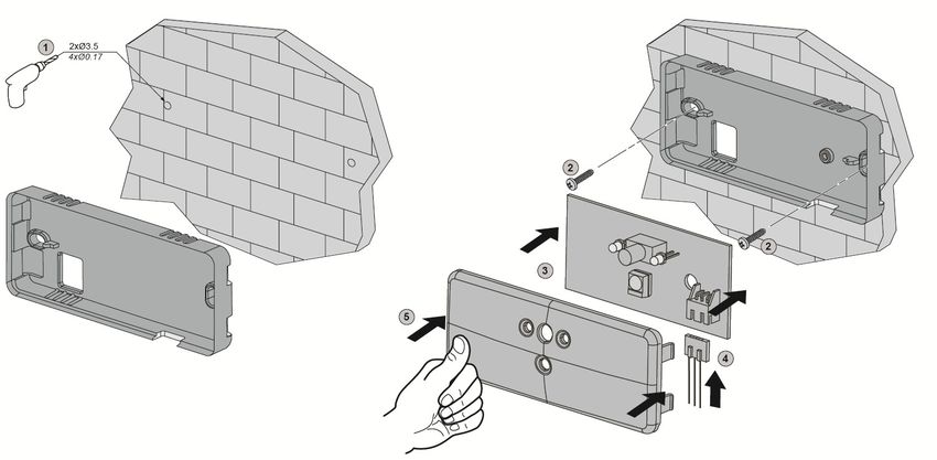
Il Terminale Remoto può essere fissato a muro utilizzando i fori provided in the plastic base with a screw/push-fit fixing system.
predisposti sulla base in plastica con un sistema di fissaggio a To proceed, open the Remote Terminal by pressing the side tabs
vite/inserto. gently so as to lift and remove the cover with display.
Per procedere occorre aprire il Terminale Remoto premendo
delicatamente le linguette laterali in modo da sollevare e
rimuovere il coperchio dotato di display.
- 13 -AUTO
AUTO
Mode
Per il posizionamento utilizzare la base stessa come dima oppure When positioning, use the base itself as a template or use the plan
utilizzare il disegno sottostante per il posizionamento dei fori di below to position the fixing holes.
fissaggio. For incoming wires, use the specially provided central hole.
Per l’ingresso cavi utilizzare il foro centrale appositamente When fixing, take care to position the base horizontally, taking care
predisposto. not to force the screws and damage the base.
Nel fissaggio prestare attenzione a posizionare la base in
posizione orizzontale evitando di sforzare con le viti per non
danneggiare la base stessa.
- 14 -Una volta fissata a muro la base del Terminale Remoto è Once the Remote Terminal base is fixed to the wall, you can
possibile procedere con i collegamenti elettrici alla morsettiera proceed with electrical connection to the terminal block on the base
presente sulla base stessa. itself.
Il collegamento ai morsetti è del tipo a molla e va effettuato Connection to the terminals is spring-loaded and should be
secondo il seguente schema: performed according to the following diagram:
Una vola collegati i cavi alla morsettiera, fissarli, con una fascetta, Once the wires have been connected to the terminal block, fix
alla linguetta “F” posta in prossimità del foro di entrata cavi. them to tab “F” near the wire entry hole using a clamp.
- 15 -12V
SIG
GND
F
I morsetti presenti, dall’alto al basso, sono: The terminals are, from top to bottom:
V alimentazione (+12V) dal morsetto 5 della scheda. V power supply (+12 V) from terminal 5 on the board
Sig segnale dal morsetto 4 della scheda Sig signal from terminal 4 on the board
GND massa dal morsetto 3 della scheda GND earth from terminal 3 on the board
Per il collegamento dei cavi premere con un cacciavite il To connect the wires, use a screwdriver to push the spring-loaded
pulsantino a molla, inserire il cavo e poi rilasciare. button, insert the wire and then release.
ATTENZIONE: CAUTION:
VERIFICARE SEMPRE CHE I CAVI SIANO BEN SALDI NEI ALWAYS MAKE SURE THE WIRES ARE FIRMLY INSERTED
MORSETTI ED UTILIZZARE SOLO CAVI DI DIAMETRO INTO THE TERMINALS, AND ONLY USE WIRES WITH A
CORRETTO IN RELAZIONE AL MORSETTO. DIAMETER SUITED TO THE TERMINAL.
NOTA: NOTE:
Per il collegamento del Terminale Remoto si consiglia We recommend the BELDEN 8762 20 AWG wire when
l’utilizzo del cavo BELDEN 8762 20 AWG. connecting the Remote Terminal.
Interfaccia e gestione del Terminale Remoto: Remote Terminal interface and management:
Come detto il Terminale Remoto è costituito da un display grafico As stated, the Remote Terminal consists of a graphic display and
e da quattro pulsanti di interfaccia. four interface buttons.
I pulsanti hanno tutti una funzione principale e delle funzioni The buttons all have a main function and additional functions
aggiuntive in base al contesto in cui vengono utilizzati. depending on the context in which they are used.
- 16 -AUTO
AUTO
Mode
In generale abbiamo: In general there is:
Mode Mode
Tasto ON/OFF – Mode. ON/OFF - Mode key.
Il tasto ON/OFF – Mode permette di accendere e spegnere il The ON/OFF - Mode key can be used to switch the Remote
Terminale Remoto e quindi avviare o fermare la regolazione del Terminal on and off, and therefore to start or stop system
sistema. regulation.
ATTENZIONE: CAUTION:
L’ACCENSIONE E/O LO SPEGNIMENTO AVVENGONO TO SWITCH IT ON AND/OR OFF, PRESS AND HOLD THE
TRAMITE UNA PRESSIONE PROLUNGATA DEL PULSANTE BUTTON FOR APPROXIMATELY 6/8 SECONDS.
DI CIRCA 6/8 SECONDI. In addition to the ON/OFF function, you can press and release the
Oltre alla funzione di ON/OFF, il tasto consente, tramite una key to change the Remote Terminal operating mode.
pressione singola, il cambio del modo di funzionamento del
Terminale Remoto.
UP key
Tasto SU. Increases displayed values, such as the set point value, or scrolls
upwards through the programming parameters.
Permette di aumentare i valori visualizzati, come il valore di set-
point, oppure scorrere verso l’alto i parametri di programmazione. DOWN key
Tasto GIU’. Decreases displayed values, such as the set point value, or scrolls
downwards through the programming parameters.
Permette di decrementare i valori visualizzati, come il valore di
set-point, oppure scorrere verso il basso i parametri di
programmazione.
FAN key
The key can be used to select the fan operating speed by cycling
Tasto VENTILATORE. through the minimum, medium, maximum and automatic speed
settings.
Il tasto permette di selezionare la velocità di funzionamento del During automatic operation, the speed changes automatically
ventilatore passando ciclicamente da velocità minima, media, depending on the difference between the ambient temperature and
massima e automatica.
the set point.
In funzionamento automatico la velocità varia automaticamente in
For 3-speed motors, parameter P16 sets the difference threshold
funzione dello scostamento tra temperatura ambiente e set-point. (between Tambient and Setpoint) which corresponds to an
Per motori 3 velocità il parametro P16 imposta la soglia di increase in speed, while for the motors controlled by the 0-10V
scostamento (tra Tambiente e Setpoint) corrispondente ad un output there is a constant regulation between the minimum and
incremento di velocità mentre per motori pilotati dall’uscita 0-10V maximum speed. A difference of 2x P16 in Tambiente in relation to
si ha una regolazione continua tra velocità minima e massima. the set point corresponds to the maximum speed setting.
Uno scostamento della Tambiente rispetto al setpoint pari a 2x The fan key corresponds to the ESC function when navigating the
P16 corrisponde alla velocità massima. machine status or programming menu.
- 17 -Il tasto ventilatore corrisponde alla funzione ESC quando si è nel
menù stato macchina o programmazione.
STATO DELLA MACCHINA MACHINE STATUS
AUTO
AUTO
Mode
Visualizzazione dello stato della macchina (menù risorse): View machine status (resource menu):
Con la pressione contemporanea di tasti e , per almeno Press and hold and simultaneously for at least 6/8
6/8 secondi, è possibile visualizzare lo stato della macchina a cui seconds to view the status of the machine to which the Remote
è collegato il Terminale Remoto. Terminal is connected.
Una volta attivato il menù è possibile scorrere le varie risorse Once the menu has been activated, you will be able to scroll
tramite i tasti e . through the various resources using keys and .
Una volta selezionato lo stato è possibile visualizzarne il valore Once the status has been selected you will be able to view its
Mode Mode
con la pressione del tasto . value by pressing .
Per stato si intende: The following are considered as statuses:
Temperatura rilevata dalla sonda acqua [H2O] The temperature detected by the water probe [H2O]
Temperatura rilavata dalla sonda aria collegata alla base [Aib] The temperature detected by the air probe connected to the base
[Aib]
Temperatura letta dal terminale LCD [AiL]
The temperature read by the terminal [AiL]
Stato dell’ingresso digitale (secondal aseguent elegenda)
The digital input status (in accordance with the following list)
0: ingresso digitale non configurato
0: digital input not configured
1: modalità economy da digitale
1: economy mode from digital
2: sistema spento da digitale
2: system off from digital
3: modalità comfort da digitale
3: comfort mode from digital
Setpoint reale usato per la termoregolazione
Actual set point used for temperature control
- 18 -NOTA: NOTE:
I valori visualizzati nel menù stato macchina provengono The values displayed in the machine status menu originate
dalla base dotata di sonda acqua, che dev’essere unica in from the base fitted with a water probe, which should be the
una zona (più fancoil connessi ad un medesimo terminale only one in the zone (several fancoils connected to the same
remoto). remote terminal).
Ne consegue che in caso di sonda acqua guasta o non It follows that, if a water probe is faulty or not installed,
installata il menù stato macchina non visualizzerà alcun the machine status menu will not display a value.
valore.
NOTE:
NOTA:
if the Remote Terminal keys are not used for a period of
nel caso non si utilizzino i tasti del Terminale Remoto per più 15 seconds or more, the terminal will exit machine status
di 15 secondi lo stesso uscirà dallo stato della macchina mode and automatically return to the main screen.
tornando automaticamente alla schermata principale.
PROGRAMMAZIONE SCHEDULING
NOTA: NOTE:
il menù di programmazione è protetto da password in modo the programming menu is password-protected so as to ensure
da garantire l’accesso solo alle persone autorizzate. that only authorised persons may access it.
Il valore di default è 15 e nel caso si desideri limitare The default value is 15 and, if you want to restrict access to
l’accesso al Terminale Remoto è consigliabile cambiarla the Remote Terminal, we recommend changing it via the
tramite il menù di programmazione. programming menu.
NOTA: NOTE:
nel caso non si utilizzino i tasti del Terminale Remoto per più if the Remote Terminal keys are not used for a period of
di 15 secondi lo stesso uscirà dal menù programmazione 15 seconds or more, the terminal will exit the programming
tornando automaticamente alla schermata principale. menu and automatically return to the main screen.
ATTENZIONE: CAUTION:
NEL CASO AL TERMINALE REMOTO CI SIANO COLLEGATE IF SEVERAL BOARDS ARE CONNECTED TO THE REMOTE
PIU’ SCHEDE, LA MODIFICA DEI PARAMETRI PORTERA’ TERMINAL, CHANGING THE PARAMETERS WILL
ALLA SOVRASCRITTURA DEI VALORI PRESENTI IN TUTTE OVERWRITE THE VALUES FOR ALL CONNECTED BOARDS.
LE SCHEDE AD ESSO COLLEGATE.
- 19 -AUTO
AUTO
Mode
Mode
Per attivare il menù programmazione occorre premere
Mode To activate the programming menu, press and hold the and
contemporaneamente il tasto ed il tasto per circa 6/8
secondi. keys together for 6/8 seconds.
Inserire il valore della password di sistema utilizzando i tasti Enter the system password value, using and to scroll
e per scorrere i valori. through the values.
Mode
Mode Press to confirm.
Premere il tasto per confermare.
Once you have accessed the menu, scroll through the parameters
Una volta nel menù è possibile scorrere i parametri tramite i tasti
using and .
e .
Mode
Una volta selezionato il parametro desiderato, premere il tasto Once you have selected the desired parameter, press to
Mode
per visualizzare il valore, scorrere i tasti e per view the value, use and to scroll through the values to
modificarlo e successivamente ancora il tasto Mode per change it and then press Mode to confirm the changes.
confermare la modifica.
Press the fan key to exit the menu without saving the
La pressione del tasto ventola consente di uscire dal menù
changes.
senza memorizzare le modifiche effettuate.
ELENCO PARAMETRI LIST OF PARAMETERS
Par. Descr. Range U.M. Default
Isteresi di Regolazione.
P00 0,2 ÷ 2,0 °C/°F 0,5
Control hysteresis.
Zona neutra (Differenziale cambio automatico modo funzionamento).
P01 1,0 ÷ 5,0 °C/°F 2,0
Neutral zone (Automatic operating mode change differential).
Unità Misura Temperatura 0 = °C; 1 = °F.
P02 0÷1 flag 0
Temperature Unit of Measurement 0 = °C; 1= °F.
Soglia Temperatura Acqua funzionalità Hot Start.
P03 30,0 ÷ 122 °C/°F 35,0
Hot Start function Water Temperature Threshold.
- 20 -Soglia Temperatura Acqua funzionalità Too Cool.
P04 12,0 ÷ 77,0 °C/°F 15,0
Too Cool function Water Temperature Threshold.
Compensazione lettura sonda locale modalità caldo.
P05 -5,0 ÷ 5,0 °C/°F 0,0
Heating mode local probe reading compensation.
Compensazione lettura sonda locale modalità freddo.
P06 -5,0 ÷ 5,0 °C/°F 0,0
Cooling mode local probe reading compensation.
Resistenza elettrica in sostituzione o integrazione
0 = Integrazione; 1 = Sostituzione.
P07 0÷1 flag 1
Electric heater as replacement or supplement
0 = Supplement; 1 = Replacement.
Soglia temperatura acqua intervento resistenza integrazione.
P09 30,0 ÷ 122 °C/°F 40,0
Supplementary electric heater cut-in water temperature threshold.
Isteresi temperatura acqua intervento resistenza integrazione.
P10 0,4 ÷ 2,0 °C/°F 2,0
Supplementary electric heater cut-in water temperature hysteresis.
Set-point Ambiente.
P11 P23 ÷ P24 °C/°F 25,0
Ambient set-point.
Tempo Post Ventilazione da spegnimento resistenze.
P12 0 ÷ 900 sec 60
Post-ventilation resistor switch-off time.
Ritardo attivazione ventola rispetto apertura valvola.
P14 0 ÷ 10 sec 0
Fan switch-on delay in relation to valve opening.
Soglia temperatura per ventilazione automatica.
P16 1,0 ÷ 5,0 °C/°F 1,0
Temperature threshold for automatic ventilation.
Isteresi temperatura acqua per Hot Start e Too Cool.
P17 0,4 ÷ 5,0 °C/°F 2,0
Water temperature hysteresis for Hot Start and Too Cool.
Differenziale Economy.
P18 1,0 ÷ 15,0 °C/°F 3,0
Economy differential.
Tempo on ventilazione periodica in Caldo.
P19 0 ÷ 900 min 1
Periodic ventilation ON time in Heating mode.
Tempo off ventilazione periodica in Caldo.
P20 0 ÷ 900 min 20
Periodic ventilation OFF time in Heating mode.
Tempo on ventilazione periodica in Freddo.
P21 0 ÷ 900 min 1
Periodic ventilation ON time in Cooling mode.
Tempo off ventilazione periodica in Freddo.
P22 0 ÷ 900 min 20
Periodic ventilation OFF time in Cooling mode.
Limite inferiore set-point.
P23 0,0 ÷ P24 °C/°F 15,0
Set-point lower limit.
Limite superiore set-point.
P24 P23 ÷ 86,0 °C/°F 30,0
Set-point upper limit.
Tempo ventilazione ON forzata in modo auto.
P25 0 ÷ 900 sec 60
Initial forced ON ventilation time in Auto mode.
Tempo ventilazione OFF iniziale forzata in modo auto.
P26 0 ÷ 900 min 600
Initial forced OFF ventilation time in Auto mode.
Tempo valvola off per lettura temperatura acqua.
P29 1 ÷ 900 sec 600
Valve OFF time due to water temperature reading.
Tempo valvola on per lettura temperatura acqua.
P30 0 ÷ 900 sec 0
Valve ON time due to water temperature reading.
- 21 -Selezione valore visualizzazione principale. 0 = Temperatura letta da NTC zona;
1 = Temperatura sonda Aria della scheda base nella quale è installata la sonda
acqua;
ddd 2 = Set-point; 3 = Set-point reale.
0÷3 flag 0
Selection of main display value. 0 = Temperature read by zone NTC;
1 = Air probe temperature for the base board on which the water probe is installed;
2 = Set point; 3 = Actual Set point.
Polarità ingresso digitale D.I. - 0 = Normalmente aperto; 1 = Normalmente chiuso.
Pdi 0÷1 flag 0
Polarity of D.I. input. - 0 = Normally open; 1 = Normally closed.
Configurabilità ingresso digitale D.I. - 0 = Contatto Economy; 1 = ON / OFF.
Fdi 0÷1 flag 1
Configurability of D.I. digital input. - 0 = Economy Contact; 1 = ON / OFF.
Minima velocità uscita analogica.
P80 0 ÷ 999 num 330
Analogue output minimum speed.
Media velocità uscita analogica.
P81 0 ÷ 999 num 660
Analogue output medium speed.
Massima velocità uscita analogica.
P82 0 ÷ 999 num 990
Analogue output maximum speed.
Modalità di funzionamento 0 = Freddo; 1 = Caldo; 2 = Freddo/Caldo/Auto.
H_C 0÷2 num 2
Operating mode 0 = Cooling; 1 = Heating; 2 = Cooling/Heating/Auto.
Valore Password.
PS1 0 ÷ 999 num 15
Password value.
Indirizzo controllore protocollo Modbus.
Adr* 1 ÷ 250 num 1
Modbus protocol controller address
Selezione baud-rate 0 = 9600; 1 = 19200; 2 = 38400.
bAU 0÷2 num 0
Baud-rate selection 0 = 9600; 1 = 19200; 2 = 38400.
Bit Parità Modbus
0 = Nessuna / 2 bit stop; 1 = Pari / 1 bit stop; 2 = Dispari / 1 bit stop.
PtY 0÷2 num 2
Modbus Parity bit
0 = None / 2 bit stop; 1 = Even / 1 bit stop; 2 = Odd / 1 bit stop.
* La modifica dell’impostazione dell’indirizzo MODBUS Adr ha effetto solo in presenza del modulo RS485.
* Changing the setting for the MODBUS address Adr only takes effect when the RS485 module is present.
In assenza di tale modulo l’indirizzo MODBUS attivo rimane sempre quello di default: 1.
If this module is not present, the active MODBUS address will always be the default one: 1.
MODO DI FUNZIONAMENTO OPERATING MODE
I principali parametri di funzionamento sono la temperatura di set- The main operating parameters are the set point temperature, the
point, la velocità del ventilatore e la modalità di funzionamento. fan speed and the operating mode.
La temperatura di set-point è la temperatura desiderata in ambiente The set point temperature is the desired ambient temperature to
a cui il sistema fa riferimento per la gestione dell’unità. which the system refers when managing the unit.
La velocità del ventilatore permette all’utilizzatore di scegliere un The fan speed allows the user to select operation at one of three
funzionamento ad una velocità fissa, selezionabile tra tre, oppure a fixed speed settings, or automatic operation.
velocità automatica. The operating mode allows the user to select the cooling, heating
La modalità di funzionamento permette all’utilizzatore di scegliere or automatic operating mode.
tra il funzionamento in raffreddamento, riscaldamento o automatico.
VENTILATION:
VENTILAZIONE: This configuration allows adjustment of the fan speed to one of the
In questa configurazione è possibile regolare la velocità del four settings, in order to have air circulation only, with no other
ventilatore, tra le quattro previste, così da avere la sola circolazione treatment.
dell’aria senza nessun tipo di trattamento.
- 22 -ATTENZIONE: CAUTION:
per il corretto funzionamento della modalità ventilazione the valves must be present for ventilation mode to work
occorre che siano presenti le valvole. properly.
IMPIANTO A 2 TUBI. 2-PIPE SYSTEM.
In questa configurazione, sull’unità, è montata una unica batteria In this configuration, the unit is fitted with a single battery, offering
con funzione di raffreddamento e di riscaldamento. cooling and heating functions.
Sulla scheda elettronica gli switch devono essere in posizione: The switches on the electronics board must be in the following
position:
ON
1 - OFF 1 - OFF
2 - OFF 2 - OFF
123
Nel caso sia presente la valvola, la stessa è unica per i due If the valve is present, it is the only one required for both operating
funzionamenti ed è normalmente chiusa. modes and is normally closed.
Sulla scheda elettronica gli switch devono essere in posizione: The switches on the electronics board must be in the following
position:
ON
1 - ON 1 - ON
2 - OFF 2 - OFF
123
Modo RAFFREDDAMENTO. COOLING mode.
In questa modalità il ventilatore rimane in moto finché la In this mode the fan continues running as long as the ambient
temperatura ambiente è superiore al valore di set-point impostato. temperature is greater than the specified set point value.
NOTA: NOTE:
Funzione Termostato di minima: Minimum Thermostat function:
per evitare l’immissione in ambiente di aria calda è possibile to prevent hot air from being released into the room, a water
impostare una valore di temperatura dell’acqua che, se temperature value can be set that, if exceeded, causes the
superiore, la valvola si apre ma il funzionamento del valve to open but fan operation to be halted.
ventilatore viene inibito. When the correct water temperature has been reached, the fan
Al raggiungimento della temperatura dell’acqua corretta, il is activated automatically.
ventilatore viene attivato automaticamente. To prevent air stratification, if the fan has been inactive for a long
Per evitare fenomeni di stratificazione dell’aria, nel caso di fermo period of time, the system automatically starts fan operation.
prolungato del ventilatore, il sistema provvede in automatico a far In cooling mode the fan is activated at minimum speed for P21
partire il ventilatore, minutes for every P22 minutes of inactivity.
Il modo freddo il ventilatore viene attivato alla velocità minima per If P21 = 0 the function is disabled.
P21 minuti ogni P22 minuti di fermo.
Se P21 =0 la funzione viene disabilitata
The activity and inactivity times are defined by parameters P19
(Periodic ventilation ON time in Heating mode) and P20 (Periodic
I tempi di attività e di fermo sono definiti rispettivamente dai ventilation OFF time in Heating mode) respectively.
parametri P19 (Tempo on di ventilazione periodica in Caldo) e P20
(Tempo off di ventilazione periodica in Caldo).
HEATING mode.
In this mode the fan continues running as long as the ambient
Modo RISCALDAMENTO. temperature is lower than the specified set point value.
In questa modalità il ventilatore rimane in moto finché la
temperatura ambiente è inferiore al valore di set-point impostato.
- 23 -Puoi anche leggere