RIDUTTORI DI PRESSIONE - PRESSURE REDUCING VALVE
←
→
Trascrizione del contenuto della pagina
Se il tuo browser non visualizza correttamente la pagina, ti preghiamo di leggere il contenuto della pagina quaggiù
RIDUTTORI DI PRESSIONE - PRESSURE REDUCING VALVE
RIDUTTORI DI PRESSIONE - PRESSURE REDUCING VALVES

    1. Presentazione
    I possibili sbalzi della pressione in rete rendono fondamentale e primaria la sua riduzione all’ingresso degli impianti.
    L’operazione, oltre che prolungare nel tempo l’efficienza dei suoi componenti e ridurne la rumorosità, consente anche un notevole
    risparmio d’acqua. Ad esempio, riducendo la pressione da 6 a 3 bar, si può calcolare una riduzione dei consumi fino al 30%.
    Le reti di distribuzione presentano spesso variazioni di pressione tra le ore diurne e quelle notturne quando, per la minore richiesta
    d’acqua, la pressione in rete aumenta naturalmente passando, ad esempio dai 10 bar diurni ai 15 bar notturni.
    E’ quindi fondamentale montare un dispositivo che sia in grado di mantenere costante la pressione a valle indipendentemente del
    variare della pressione a monte dello stesso.
    Rubinetterie Bresciane presenta la nuova gamma di riduttori EURO che soddisfa tutte le esigenze sopre elencate.

    1. Introduction
    Pressure variations of the water supply do require a stabilization while entering the plant. This operation does protect the lifetime of
    the single parts of the pipeline, reduces the water noise and moreover does generate a significant saving of water.
    By reducing the line pressure from 6 to 3 bar, a saving up to 30% water is reached.
    Further, water supply lines do show huge pressure variations between day and night time. Due to a limited request of water during
    night time, water pressure tends to raise significantly.
    It’s therefore strongly recommended to install devices which may stabilize the downstream pressure in case of pressure variation
    on the upstream side.
    At this purpose Rubinetterie Bresciane is glad to introduce the new range of EURO pressure reducing valves.

2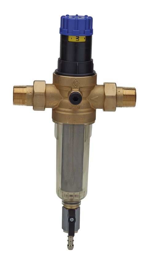
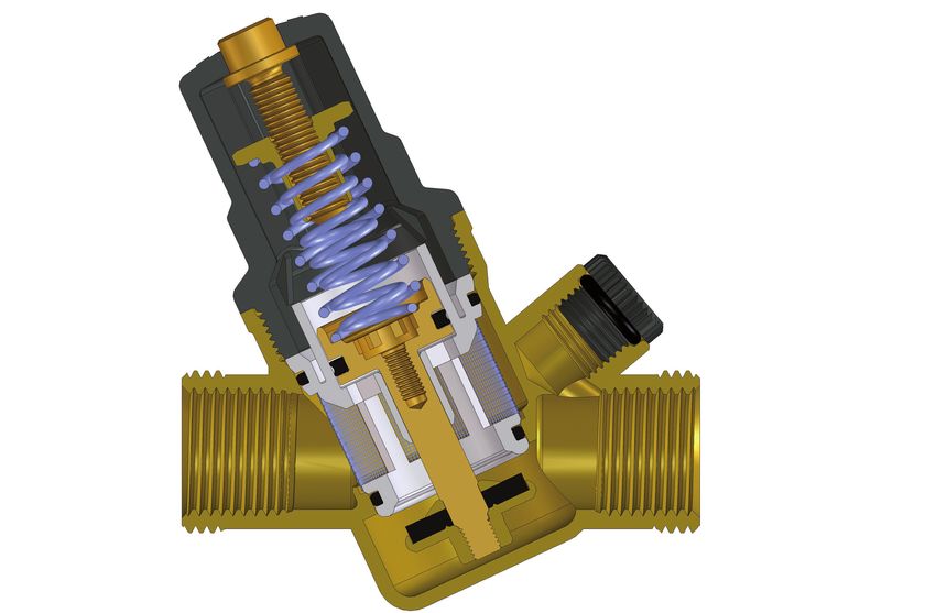
ELEMENTI ESSENZIALI DEL RIDUTTORE - MAIN PARTS OF THE PRESSURE REDUCING VALVE

                                                                                  Appoggio basculante della molla
     Membrana più robusta ed elastica                                         Migliora il tempo di reazione dell’otturatore,
     Migliora la resistenza alla rottura e lo                                  sia in apertura sia in chiusura, facendolo
        scalzamento della membrana                                                 lavorare sempre in modo lineare e
          sollecitata dai colpi d’ariete                                      scaricando la forza della molla solo in asse
          e dalla pressione di ritorno
                                                                                      Bascule seat of the spring
      More flexible and robust membrane                                         It does improve the reaction time of the
  It does improve the resistance due to water                                  obstructor either for opening and closing.
             hammer and backflow                                              Further the whole power of the spring loads
                                                                                 on the central shaft of the device only

                                                                                    Guarnizione della tenuta rinforzata
            Retina rompi flusso                                                       Migliora la resistenza alla rottura
        Elimina i rumori di passaggio                                                e lo scalzamento della guarnizione
  dell’acqua e le risonanze che possono                                               di tenuta dovuti dai colpi d’ariete
   presentarsi in particolari circuiti con                                                e dalla velocità dell’acqua
        alta pressione o alta velocità
              dell’acqua stessa                                                               Reinforced seat
                                                                                       It does improve the resistance
        Strainer for flow breaking                                                   due to water hammer and backflow
     It does reduce water noise and
         resonacne which may be
        generated by high pressure
       or by high velocity of the flow

                        Otturatore inox integrale                                      Guarnizione a labbro
      Le parti di scorrimento sulle guarnizioni dell’otturatore sono    Abbinata al trattamento anticalcare dell’otturatore,
      trattate in modo da ridurre sensibilmente i depositi calcarei,   riduce i problemi di bloccaggio dell’otturatore stesso
                      bloccaggi e malfunzionamenti.                        dovuti a sporcizia e depositi calcarei presenti
                  La struttura in inox riduce i problemi di                    nell’acqua di rete, ed, inoltre, riduce i
              cavitazione e corrosione, anche se la velocità                fenomeni di isteresi, migliorando i tempi di
                       dell’ acqua supera i 2 m/sec                                    reazione del riduttore

                     Solid stainless steel shutter                                           Lip seat
     Very smooth outside surface of sliding parts of the shutter for     Along with the smooth surface treatment of the
                reducing limestone to get choked on it.                 shutter, does improve resistance against dirt and
          Further, the stainless steel material allows a much                     calcareous deposits of water.
           better resistance against cavitation and corrosion               Furthermore it does reduce phenomenon
            even by velocity of the fluid faster than 2 m/sec          of hysteresis and does improve the reaction time of
                                                                                       the pressure reducer

                                                                                                                                3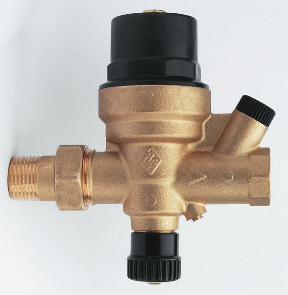
Scelta della dimensione del riduttore di pressione
    Supponendo che in un impianto domestico la velocità dell’acqua è compresa tra 1 e 2 m/sec, fascia sempre consigliata per evitare
    fenomeni di cavitazione, per stabilire la dimensione del riduttore di pressione da installare, e considerando un fabbisogno di 30 l/min.,
    tracciare una linea verticale in corrispondenza del valore indicato sulle ordinate, fino ad incrociare la retta del riduttore da 3/4”
    compreso nella fascia.
    Determinazione delle caratteristiche idrauliche del riduttore di pressione (grafico A)
    Per determinare la portata di un riduttore di pressione da 1”, tracciare una linea orizzontale in corrispondenza del valore di 2 m/sec
    fino ad incrociare la retta corrispondente alla misura del riduttore scelto. Tracciare una linea verticale fino a intersecare la linea delle
    ordinate, leggendo una portata di 80 l/min.
    Determinazione della caduta di pressione del riduttore (grafico B)
    Per determinare la perdita di carico di un riduttore di pressione da 1/2”, con una portata di 30 l/min, tracciare una linea verticale
    in corrispondenza del valore di portata indicato sulle ordinate, fino ad intersecare la curva corrispondente al riduttore di pressione
    da 1/2”, tracciare in questo punto una linea retta orizzontale che indicherà sulle ascisse il valore di caduta di pressione da 0,7 bar.

    Size selection of pressure reducer
    Made by taking into consideration a plumbing line with a velocity of water between 1 and 2 m/sec, which is the suggested value to avoid
    cavitation phenomenon. For selecting a suitable size of a pressure reducing valve to be installed with a requirement of 30 l/min, draw a
    vertical line in correspondence to the value on the ordinate until it crosses the 3/4” reducer line (since included in the advisable area).
    Calculation of the hydraulic features of a pressure reducing valve (chart A)
    To calculate the flow rate of a 1” pressure reducer, draw a horizontal line in correspondence to the value 2 m/sec until it crosses
    the line corresponding to the chosen reducer. Draw a vertical line until it intersects the ordinate axis at 80 l/min.
    Calculation of the pressure drop of a pressure reducing valve (chart B)
    In order to calculate the pressure drop of a 1/2” reducer with a flow of 30 l/min., draw a vertical line in correspondence to the value
    indicated on the y axis, until it crosses the 1/2” reducer curve. Starting from this point draw a horizontal line which will show on the
    x axis the pressure drop of 0,7 bar.

GRAFICO VELOCITA’ DI CIRCOLAZIONE - FLOW SPEED DIAGRAM

    Ve locità di circolazione (m/sec)
                                                                                                      1"1/4
                                                                                                              1"1/2
                                                                              1/2"

                                                                                          3/4"

    Flow speed (m/sec)                    X
                                                                                                 1"

                                                                                                                      2"
                                    5
                                    4
                                    3
                                    2

                                    1

                                   0.5
                                   0.4
                                   0.3
                                    0.2

                                    0.1                                                                          Y
                                          3    5     10       20 30 40 50                100      200 300 500 700 l/min
                                                                                                                               Po r tata
                                          0.2 0.3    0.6      1.2    2    3          5           10           30       m /h
                                                                                                                           3   Fl ow rate

                                                                                                                                Grafico-Chart A

4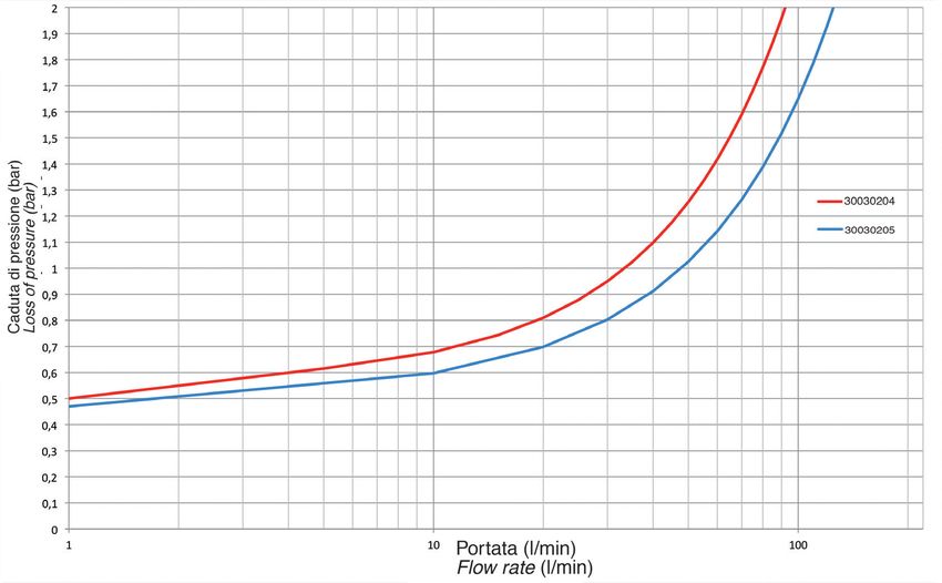
GRAFICO PERDITE DI CARICO - DROP LOSS DIAGRAM

             Caduta di pressione (bar)
             Loss of pressure (bar)

                                                                                                              1"1/4
                                                                                                                      1"1/2
                                                                                       1/2"

                                                                                                  3/4"
                                               X

                                                                                                         1"

                                                                                                                              2"
                                         1.5

                                         1

                                         0.7

                                         0.5
                                         0.4

                                         0.3

                                         0.2

                                                                                                                                         Y
                                               0.2         0.5       1       2        3 4 5              10   20 30 40 50           m 3 /h
                                                                                                                                                    Po r tata
                                                                                                                                                    Flow rate
                                                       5     10 15           30       50                              500            l/min

                                                                                                                                                         Grafico-Chart B

   Determinazione delle zone di cavitazione
   La cavitazione è un fenomeno fisico che si determina all’interno di tutti i fluidi, per l’elevata velocità assunta dal flusso che viene
   intercettato. L’eccessivo aumento di questa provoca lo scoppio delle bolle di aria (o cavità) che sono contenute e trasportate dal fluido.
   L’aria innesca onde di pressione e depressione cariche di energia d’urto, possibile causa della prematura corrosione di tutti i
   dispositivi di intercettazione. Nel grafico C, sono state individuate le aree che identificano le possibili zone di lavoro del riduttore.
   La zona ideale per un suo corretto funzionamento e per un suo corretto mantenimento è la zona blu (zona n.3).

   Cavitation range definition
   Cavitation means that cavities are forming in the liquid because of high velocity. The cavities or bubbles collapse when they
   pass into the higher regions of pressure causing noise, vibration, and damage (including corrosion) to many of the components.
   In the chart we can identify different working areas, the pressure reducing/regulating valve works in the correct way if we are in the
   blue area (area n°3).

RAPPORTO TRA LA PRESSIONE MONTE/VALLE - RELATIONSHIP BETWEEN UPSTREAM AND DOWNSTREAM
PRESSURE

         Pressione in ingresso
            Inlet pressure
                                    20
                              bar
                                    18                                                                                             ZONA DI CAVITAZIONE
                                                       1                                                                       1
                                    16                                                                                             CAVITATION AREA
                                    14
                                    12                           2                                                             2   ZONA DI PENDOLAZIONE
                                                                                                                                   INSTABILITY AREA
                                    10
                                    8                                                                                              ZONA DI LAVORO
                                                                             3                                                 3
                                    6                                                                                              WORKING AREA

                                    4
                                    2

                                                   1   2     3           4        5           6
                                                                                                              Pressione in uscita
                                                                                                               Outlet pressure                           Grafico-Chart C

                                                                                                                                                                           5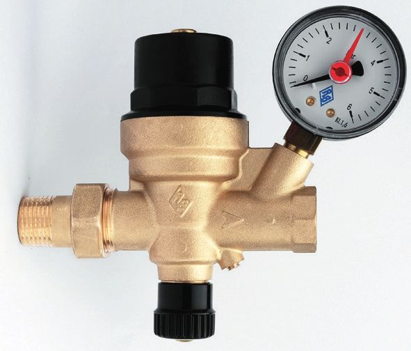
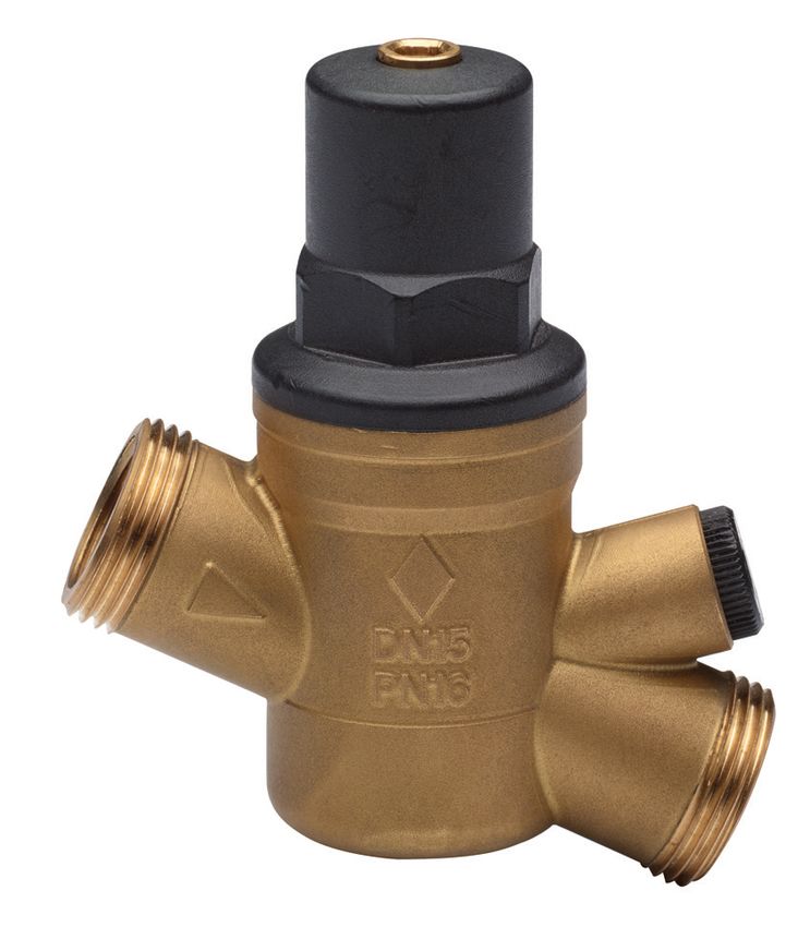
Caratteristiche principali - Main features

                                          art. 300000

                                          art. 300030                                            art. 300050
                                                                                                                                   Fig.1

    Serie:
    Art. 300000 da 1/2 a 1”1/4: Regolazione con volantino e display di lettura graduato ed orientabile.
    Art. 300030 da 1/2 a 2”: Regolazione con brugola.
    Art. 300050 da 1/2 a 1”1/4: Regolazione con volantino e display di lettura graduato ed orientabile e con filtro autopulente.
    Connessioni:
    a) Maschio/Maschio a bocchettone: EN 10226-R.
    b) Femmina/Femmina: EN 10226-Rp.
    c) n° 2 attacchi manometro: EN 10226-Rp 1/4 (femmina) da 1/2 a 1”1/4.
    d) n° 2 attacchi manometro: ISO 228-G 1/4 (femmina) da 1”1/2 a 2”.
    DN:
    Artt. 300000-300050 da DN15 a DN32.
    Art. 300030 da DN15 a DN50.
    Filtro:
    a) In acciaio INOX AISI 304 posizionato in entrata, capacità filtrante 500 μm ( F ) da 1/2 a 2”.
    b) In acciaio INOX AISI 304, in maglia REPS, capacità filtrante 100 μm ( F1 ) da 1/2 a 1”1/4.
    Corpo ottone CW617N, UNI EN12165
    Trattamento esterno sabbiato giallo.
    Per art. 300030 1”1/2 e 2” la sede dell’otturatore è intercambiabile ed è in acciaio inox AISI 316.
    Collaudo:
    Eseguito elettronicamente al 100%, con settaggio della pressione a 3 bar (art. 3000030 1”1/2-2” a 4 bar).

6
Series:
Art. 300000 from 1/2” to 1”1/4: outlet setting by means of a wheel handle, with numbered and adjustable display.
Art. 300030 from 1/2” to 2”: outlet setting by means of an allen key.
Art. 300050 from 1/2” to 1”1/4: outlet setting by means of a wheel handle, with numbered and adjustable display, assembled with a
self-cleaning strainer.
Threads:
a) Both sides outer Male with union tails as per EN 10226-R standard.
b) Both sides, 1”1/4 excluded, inner Female as per EN 10226-Rp.
c) From 1/2” to 1”1/4 sizes, n° 2 female 1/4” threaded.
connections as per EN 10226-Rp for pressure gauge.
d) For 1”1/2 and 2” sizes, n° 2 female 1/4” threaded connections as per ISO 228-G for pressure gauge.
DN:
Artt. 300000-300050 from DN15 to DN32.
Art. 300030 from DN15 to DN50.
Strainer :
a) From 1/2” to 2” stainless steel AISI304 fitted on the inlet, filtration capacity 500 µm.
b) From 1/2” to 1”1/4 stainless steel AISI304 REPS mesh, filtration capacity 100 µm (F1).
Body:
Yellow finished and sandblasted art. 300030 1”1/2 and 2” with replaceable stainless steel AISI 316 obstructor.
Testing:
By means of electronic test bench on 100% of production.

2. Condizioni di esercizio
• Pressione nominale in entrata (PN): artt. 300000 e 300030: 30 bar, art.300050: 16 bar.
• Regolazione pressione in uscita: da 1,5 a 6 bar.
• Minima pressione differenziale: 1 bar.
• Kv coefficiente di efflusso (m3/h): vedi tabella tecnica.
• Limiti di temperatura: acqua da 0°C a +70°C, aria da 0°C a +70°C .
• Fluidi intercettabili: acqua, aria, altri fluidi a richiesta.
NB: Il fluido che attraversa il riduttore di pressione deve essere compatibile con i materiali di costruzione del riduttore di pressione
stesso.
Per ricevere informazioni tecniche più dettagliate relative alla compatibilità con i materiali di costruzione utilizzati, contattare il
personale tecnico di Rubinetterie Bresciane.
• Direzione del flusso: UNIDIREZIONALE (vedi freccia sul corpo).

2. Working conditions
• Inlet nominal pressure (PN) in bar: Artt. 300000 e 300030: 30 bar, Art.300050: 16 bar.
• Setting of the outlet pressure: from 1.5 to 6 bar.
• Lowest differential pressure: 1 bar.
• Kv value (m3/h): please refer to the chart.
• Working temperature: water from 0°C to +70°C, air from 0°C to +70°C.
• Intercepted fluids: water and air; other fluids on request.
Notice: the fluid interecepted by the pressure reducing valve must be compatible with its materials.
Additional information regarding compatibility with materials are available with Rubinetterie Bresciane technical office.
• Fluid direction: ONE-WAY (as per arrow on the body).

                                                                                                                                      7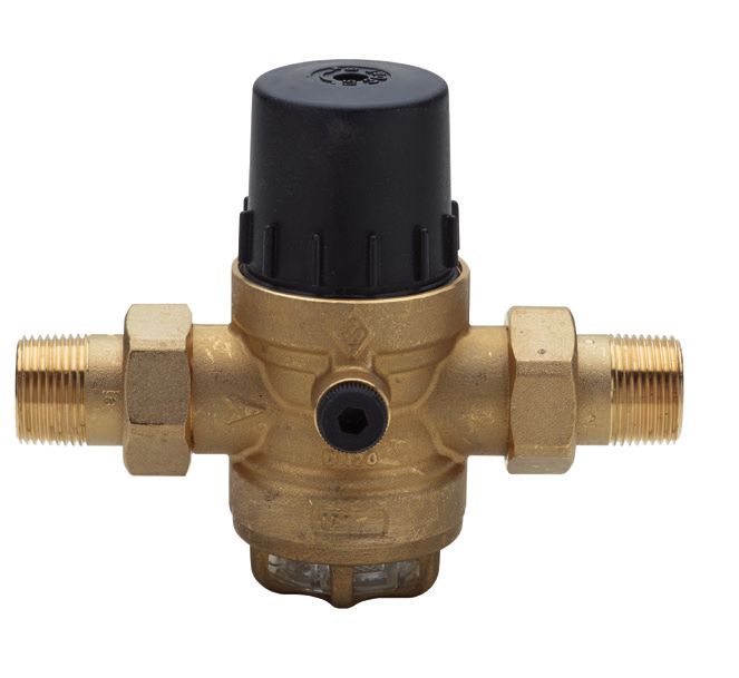
Elenco ricambi - Spare parts

        MANOMETRO 1/4” ATTACCO ASSIALE 0-6 bar                                             GRUPPO FILTRO 100 µm AUTOPULENTE 1/2 - 1"1/4
     PRESSURE GAUGE 1/4” AXIAL CONNECTION 0-6 bar                                          STRAINER SET 100 µm SELFCLEANING 1/2 - 1"1/4
                    art 30090402                                                                          art. 30090200

                                                                                                                   CHIAVE - SPANNER
                                                                                                                     art. 30090300

                                                                    FILTRO - STRAINER 500 µm
                                                                         RI440 (1/2 - 3/4)
       KIT CODOLI - UNION TAILS                                          RI442 (1"1/2 - 2")
       RI577 (1/2) - RI578 (3/4)
       RI579 (1") - RI584 (1"1/4)
       RI589 (1"1/2) - RI590 (2")

                                                                                                                     FILTRO - STRAINER 100 µm
                                                                                                                          RI470 (1/2-1”1/4)

                                                    CARTER TRASPARENTE
                                                      TRANSPARENT CUP
                                                RI518 (1/2 - 3/4) - RI448 (1"1/2 - 2")

      GRUPPO OTTURATORE + GUARNIZIONE A LABBRO
                  OBSTRUCTOR KIT + LIP SEAT
      RI597 (1/2 - 3/4) - RI598 (1" - 1"1/4) - RI599 (1"1/2 - 2")                                                                            Fig. 2

    Come funziona un riduttore di pressione e/o riduttore di pressione con filtro autopulente:
    Il riduttore di pressione di Rubinetterie Bresciane “EURO” è un prodotto a sede compensata, utilizzabile per garantire una pressione in uscita
    “costante” e per salvaguardare la rete dell’utente indipendentemente dalla pressione in entrata o eventuali “colpi d’ariete“ e può venire installato
    sia a monte sia a valle del contatore d’utenza.
    FILTRAGGIO:
    Al suo interno i fluidi sono intercettati in entrata da un ampio filtro ispezionabile. La maglia da 500 a 100 micron intercetta le sostanze
    abrasive preservandone la funzionalità, salvaguardando l’impianto e riducendo sensibilmente il consumo d’acqua.
    CAMPI D’IMPIEGO:
    Ospedali, alberghi, abitazioni specie se pedemontane, industrie, dove necessitano pressioni controllate.

    How does a pressure reducing valve and /or a pressure reducing valve with self-cleaning strainer work:
    The pressure reducing valve “EURO” of Rubinetterie Bresciane is made with a balanced seat system capable to maintain a stable outlet
    pressure to protect the down-stream pipeline from inlet pressure peaks and water hammer.
    FILTRATION:
    The fluids are intercepted at the inlet by a large inspectionable strainer from 500 to 100 micron mesh to protect the inner part and reduce
    water consumption significantly too.
    WHERE TO USE:
    Hospitals, hotels, houses, industries, whenever control of pressure is required.

8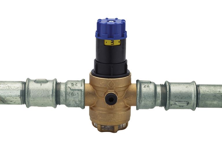
3. Installazione (Fig.3)
PREMESSA:
• L’installazione deve avvenire nel rispetto della regola dell’arte.
• Il luogo di destinazione deve essere facilmente accessibile e ben visibile per effettuare le operazioni di manutenzione.
Deve essere assolutamente protetto dal gelo.
E’ CONSIGLIATO
     • In entrata: prevedere una valvola on/off (X).
     • In uscita: prevedere una valvola di ritegno, tipo art. 100000 (R), a protezione del riduttore, una valvola on/off per scaricare, tipo
     art. 4904 (Y), e una valvola on/off tipo art. 2020 (Z).
COLLEGAMENTO DEL RIDUTTORE:
• Chiudere le valvole in entrata (X) ed in uscita (Y e Z).
• Utilizzando le connessioni filettate del corpo del riduttore, collegare il dispositivo alla condotta.
• Aprire la valvola in entrata (X) e verificare che non ci siano perdite sulle connessioni filettate.
• Se non ci sono perdite aprire la valvola in uscita (Z).

3. Installation (Fig.3)
NOTICE:
• The installation shall be made in compliance with the state of the art.
• The installation site must be easily accessible and clearly visible for maintenance purposes. A frost isolation must be provided.
IT IS SUGGESTED
     • Inlet: to fit a shut-off ball valve (X).
     • Outlet: to fit a check valve art. 100000 (R) on the down-stream side along with a shut-off hose ball bib-cock art. 4904 (Y) for draining
     purposes and an additional shut-off ball valve art. 2020 (Z).
ASSEMBLY OF THE PRESSURE REDUCING VALVE:
• Close both the inlet (X) and outlet (Y and Z) shut-off ball valves.
• Fit the threaded connections of the pressure reducing valve to the pipeline.
• Open the inlet shut-off valve (X) and check if any leakage at both connections.
• If thight, open down-stream shut-off ball valve (Z) too.

                                                                                                                          Z

                                                                                        R

                            X

                                                                                                                                      Y

                                                                                                                                      Fig. 3

                                                                                                                                               9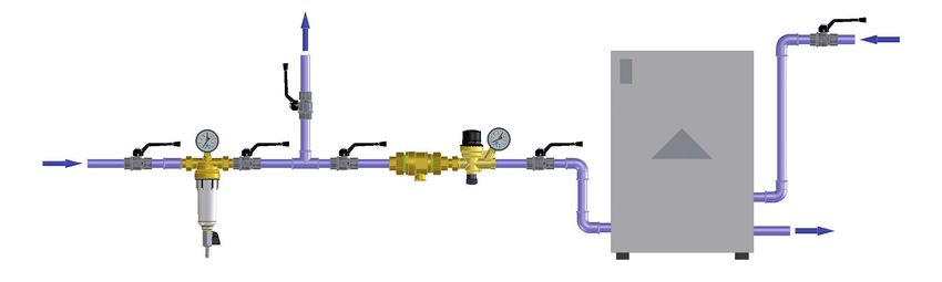
4. Regolazione della pressione in uscita (Fig.4)
     AUMENTO DELLA PRESSIONE:
     1) Chiudere la valvola in uscita (Z) e ruotare in senso orario il volantino blu finchè non appare sul display graduato (giallo) il valore
     della pressione desiderata.
     NB: se si desidera una regolazione precisa procedere come segue:
     2) Chiudere le valvole in entrata ed in uscita (X e Z) e scaricare la pressione usando la valvola (Y).
     3) Montare il manometro al posto del tappo ed aprire la valvola entrata (X).
     4) • Artt. 300000 e 300050: ruotare in senso orario, manualmente o con la chiave art. 30090300 il volantino blu e controllare la
     pressione sul manometro.
        • Art. 300030: ruotare in senso orario, regolando con la chiave a brugola.
     5) Aprire la valvola di scarico (Y) per qualche secondo e lentamente richiuderla.
     6) Controllare che la pressione sul manometro non sia variata altrimenti ripetere come dal punto 4.

     DIMINUZIONE DELLA PRESSIONE:
     1) Chiudere la valvola in uscita (Z) e ruotare in senso antiorario il volantino blu finchè non appare sul display graduato (giallo) il valore
     della pressione desiderata.
     NB: Se si desidera una regolazione precisa procedere come segue:
     2) Chiudere le valvole in entrata ed in uscita (X e Z) e scaricare la pressione usando la valvola (Y).
     3) Montare il manometro al posto del tappo ed aprire la valvola entrata (X).
     4) • Artt. 300000 e 300050: ruotare in senso antiorario, manualmente con la chiave art. 30090300 il volantino blu e controllare la
     pressione sul manometro.
        • Art. 300030: ruotare in senso antiorario, regolando con la chiave a brugola.
     5) Aprire la valvola di scarico (Y) per qualche secondo e lentamente richiuderla.
     6) Controllare che la pressione sul manometro non sia variata altrimenti ripetere come dal punto 4.

     4. Setting of outlet pressure (Fig.4)
     INCREASING THE OUTLET PRESSURE
     1) Shut-off the ball valve (Z) on the down-stream side, turn clockwise the blue wheel until the requested down-stream pressure
     value appears on the yellow display.
     Notice: if a precise down-stream pressure is required please proceed as follows.
     2) Close both inlet (X) and outlet (Z) shut-off ball vales and drain the pressure by means of the bib-cock (Y).
     3) Fit the pressure gauge on the body and then open the inlet shut-off ball valve (X).
     4) • Artt. 300000 and 300050: turn clockwise the blue wheel by means of the spanner art. 30090300 and check the pressure on the
          gauge.
        • Art. 300030: turn clockwise and set by means of an allen key.
     5) Open for few seconds only the drain bib-cock (Y) and close it again slowly.
     6) If gauge shows a pressure drop, please repeat procedure from point 4.

     DECREASING THE OUTLET PRESSURE
     1) Turn counterclockwise the blue wheel until the requested down-stream pressure value appears on the yellow display.
     Notice: if a precise down-stream pressure is required please proceed as follows.
     2) Close both inlet (X) and outlet (Z) shut-off ball vales and drain the pressure by means of the bib-cock (Y).
     3) Fit the pressure gauge on the body and then open the inlet shut-off ball valve (X).
     4) • Artt. 300000 and 300050: turn counterclockwise the blue wheel by means of the spanner art. 30090300 and check the pressure
           on the gauge.
        • Art. 300030: turn counterclockwise and set by means of an allen key.
     5) Open for few seconds only the drain bib-cock (Y) and close it again slowly.
     6) If gauge shows a pressure drop, please repeat procedure from point 4.

10
Brugola
Allen key
Volantino blu con display graduato giallo
Blue hand weehl with downstream pressure display
Z
R
X
Y
Fig. 4
115. Manutenzione ordinaria del filtro (Fig.5)
• Artt. 300000 e 300030
Si consiglia di controllare periodicamente il contenitore trasparente del filtro (D).
Se necessita di pulizia seguire la seguente istruzione:
1) Chiudere le valvole in entrata (X) ed in uscita (Z) e svitare la gabbia in ottone (E) con la chiave art. 30090300.
2) Togliere il filtro (F) e lavarlo con acqua corrente.
3) Mettere il filtro (F) nel contenitore trasparente (D) ed inserirli nell’alloggiamento del riduttore di pressione.
4) Riavvitare la ghiera di contenimento in ottone (E).
5) Aprire lentamente la valvola in entrata (X) e, successivamente ma sempre lentamente, la valvola in uscita (Y) per riempire
l’impianto.
NB: L’installazione del kit di filtraggio autopulente (art. 30090200) al posto del normale filtro può essere effettuata avvitando
direttamente la tazza del filtro sulla filettatura del corpo del riduttore (da 1/2” a 1”1/4) con la chiave art. 30090300.
• Art. 300050 con filtro autopulente
1) Per effettuare la pulizia, è sufficiente aprire la valvola (M) posizionata sul fondo della tazza trasparente (T) almeno per 15 sec.
2) Per una pulizia più accurata dei componenti interni, (F1) svitare la tazza trasparente (T) con la chiave art. 30090300.
5. Maintenance of strainer (Fig.5)
• Artt. 300000 and 300030
It is suggested to periodically check the transparent cup (D) containing the strainer. If cleaning is required, these are the instructions:
1) Shut-off both inlet (X) and outlet (Z) ball valves; unscrew the bottom brass cage (E) by means of the spanner art. 30090300.
2) Remove the strainer (F) and clean it with water.
3) Insert the strainer (F) into the plastic cup (D) and fit them into the pressure reducing valve.
4) Screw the bottom brass cage (E).
5) Slowly open the inlet shut-off ball valve (X) first and then, slowly again, do open the outlet shut-off ball valve (Y) to fill the pipeline.
Notice: the installation of the long self-cleaning strainer art. 30090200 instead of the standard one, can be effected by means of the
same spanner art. 30090300 (suitable for pressure reducing valves from 1/2” to 1”1/4 only).
• Art. 300050 with self-cleaning strainer
1) Clean the strainer by opening for at least 15 seconds the drain ball valve (M) fitted on the bottom side of the cup (T).
2) For a more accurate cleaning of the cartridge (F1), do remove the entire strainer (T) from the pressure reducing valve by means
of the spanner art. 30090300.
F1
F
D
T
E
M
Fig. 5
126. Verifica periodica dell’efficienza del riduttore (Fig.6)
Si consiglia di effettuare il controllo almeno una volta all’anno.
IMPORTANTE: è opportuno che la manutenzione venga eseguita da personale qualificato.
1) Chiudere le valvole in entrata ed in uscita (X e Z) e scaricare la pressione usando la valvola (Y).
2) Montare il manometro al posto del tappo ed aprire la valvola entrata (X).
3) Aprire la valvola di scarico (Y) per qualche secondo e lentamente richiuderla.
4) Controllare che la pressione sul manometro rimanga stabile e corrisponda al valore della pressione che era impostata sul display
graduato (giallo).
Nel caso in cui si verificano anomalie (esempio: la pressione continua lentamente a salire) procedere come segue:
5) Chiudere le valvole in entrata (X) ed in uscita (Z).
6) • Artt. 300000 e 300050: senza togliere il volantino blu, svitare la ghiera superiore (G) con la chiave art. 30090300, utilizzando
una pinza estrarre la cartuccia dell’otturatore.
• Art. 300030: svitare il cappellotto (C) con un giratubi, premendolo il meno possibile.
7) Procedere con il controllo delle guarnizioni di tenuta, della membrana dell’otturatore e dei vari componenti.
8) Se necessario, sostituire l’otturatore (vedi kit di ricambio Fig. 2).
9) Ponendo attenzione a tutti i particolari, procedere con il rimontaggio.
ATTENZIONE: avvitare la ghiera (C o G) manualmente, per quanto consentito. Successivamente, chiudere con un appropriato
utensile come indicato nella Tabella 1.
10) Riaprire lentamente le valvole in entrata (X) ed in uscita (Z).
11) Controllare il valore di pressione in uscita, sul manometro campione, per verificare se il problema è stato risolto.
6. Periodic check of the pressure reducing valve (Fig.6)
It is suggested to check the pressure reducing valve once a year.
MOST IMPORTANT: it is recommended that maintenance is made by qualified staff.
1) Shut-off both inlet and outlet valves (X e Z) and drain pressure by means of the valve (Y).
2) Remove plug and fit pressure gauge, open inlet valve (X).
3) Open the drain valve (Y) for a few seconds and then shut it off slowly.
4) Check that pressure shown on the gauge remains stable and matches with the downstream pressure value on the yellow
display.
In case of pressure changes (for instance the pressure tends to increase) please proceed as follows:
5) Shut-off both inlet (X) and outlet (Z) ball valves.
6) • Artt. 300000 and 300050: without removing the blue wheel, unscrew the black cap (G) by means of the spanner art. 30090300,
then by means of a pliers pull and remove the shutter.
• Art. 300030: unscrew with most care the cap (C) by means of a spanner.
7) Do check all seats, the membrane and all parts of the shutter.
8) If required, do replace the whole shutter (please refer to the spare kit Fig. 2).
9) Carefully assembly all parts again and tighten.
WARNING: Screw the cap (C o G) by hand, till the end. Then, tighten by means of proper tools as shown in Table 1.
10) Open both shut-off valves (X) and (Z) with care.
11) Check the downstream pressure by means of a sample gauge.
GIRI DI SERRAGGIO - TIGHTENING TURNS
MISURE - SIZE
MIN. MAX.
1/2” - 3/4”- 1”1/2 - 2” 1/4 1/3
1” - 1”1/4 1/3 1/2
Tab. 1
13C
G
Estrarre con pinza
Remove with a plier
Z
Rete
Net
R
X
Y
Fig. 6
14SOLUZIONE MONTAGGIO TUBAZIONE - MOUNTING SOLUTIONS
ARTT. 300000 - 300030 - 300050 - 300200
SOLUZIONE 1 SOLUZIONE 2
SOLUTION 1 SOLUTION 2
SOLUZIONE 3 SOLUZIONE 4
SOLUTION 3 SOLUTION 4
CON GLI ARTICOLI INDICATI NELLO SCHEMA, GRAZIE ALLE FILETTATURE INTERNE/ESTERNE, SI POSSONO REALIZZARE
QUATTRO TIPI DI CONNESSIONI DIVERSE PER IL COLLEGAMENTO ALL’IMPIANTO.
Soluzione 1: connessione del nipples femmina con il bocchettone maschio.
Soluzione 2: connessione del tubo maschio (di una misura maggiore a quella del riduttore) con filettatura femmina del girello del
riduttore di pressione (ottenibile avvitando il bocchettone all’interno della filettatura del corpo stesso).
Soluzione 3: connessione del tubo maschio con la filettatura interna femmina del riduttore di pressione.
Si consiglia di lasciare i dadi (forniti in dotazione) avvitati sulla filettatura esterna del riduttore come protezione e/o riutilizzo.
Soluzione 4: connessione del nipples femmina (di una misura maggiore a quella del riduttore) con la filettatura maschio esterna del
riduttore di pressione.
THANKS TO THE INNER/OUTER THREADS, FOUR DIFFERENT KIND OF CONNECTIONS CAN BE OBTAINED FOR
THE ASSEMBLY ON THE PIPELINE
Solution 1: connection between a female nipple and a male union tail.
Solution 2: connection between a male pipe (a size bigger than the pressure reducer’s one) and the female ring nut thread of the
pressure reducer (the male union tail with ring nut has to be screwed into the inner female threads of the pressure reducer).
Solution 3: connection between a male pipe and a female inner thread of the pressure reducer.
Solution 4: connection with a female nipple (a size bigger than the pressure reducer’s one) and the outer male thread of the
pressure reducer.
15serie EURO
Art. 300000
Riduttore stabilizzatore di pressione a sede compensata, regolazione da 1,5 a 6
bar, sistema di filtraggio 500 micron a monte con dado e cannotto.
Pressure reducing and regulating valve with balanced seat, outlet setting from
1,5 to 6 bar, with upstream 500 micron flow filtering system, connections with
ring nut and male union tails.
Art. 300002: senza codoli - without male union tails
ØA
6 13 2
ØD1UNI EN 10226-1 Rp
ØD1UNI EN 10226-1 Rp
1 28 14
5 29 15
20 30
ØD2UNI EN 10226-1 R
16
ØD2UNI EN 10226-1 R
ØD UNI ISO 228/1-G
ØD UNI ISO 228/1-G
h1
22
I1 I1 9
H
12 24 27 25
12
26
21 23
18
h
I I
3 4 4 10
L1 3
L 11 19
7
17
8
POS. DENOMINAZIONE PART NAME MATERIALE-MATERIALS N°P
1 ASTA OTTURATORE STEM OF THE SHUTTER OTTONE CW 614N UNI EN 12164 1
2 MOLLA SPRING ACCIAIO /STEEL C85 CL C 1
3 CANNOTTO MALE UNION TAIL OTTONE CW 617N UNI EN 12165 2
4 GUARNIZIONE PIANA FLAT SEAT FIBRA/FIBER 2
5 CAPPELLOTTO CAP PPA 1
6 VOLANTINO HANDWHEEL PA6 1
7 TAPPO PLUG PA6 2
8 TAPPO BOWL OTTONE CW 617N UNI EN 12165 1
9 O-RING O-RING NBR 1
10 O-RING O-RING NBR 2
11 O-RING O-RING EPDM PEROX 1
12 DADO NUT OTTONE CW 617N UNI EN 12165 2
13 VITE SCREW ACCIAIO/STEEL 1
14 RONDELLA WASHER ACCIAIO/STEEL DD11 1
15 RONDELLA WASHER ACCIAIO/STEEL DD11 1
16 RONDELLA WASHER OTTONE CW 617N UNI EN 12165 1
17 CARTER TRASPARENTE TRANSPARENT CUP PA 12 1
18 OTTURATORE OBSTRUCTOR ACCIAIO INOX/S.STEEL 1.4408 CF8M 1
19 FILTRO STRAINER ACCIAIO INOX AISI 304 1
20 GHIERA ESTERNA RING NUT PA 1
21 GUARNIZIONE SEAT NBR 1
22 BUSSOLA BUSH POM 1
23 GHIERA RING NUT OTTONE CW 614N UNI EN 12164 1
24 CORPO BODY OTTONE CW 617N UNI EN 12165 1
25 GUARNIZIONE PIANA FLAT SEAT NBR 1
26 ROMPIGETTO SPRAY NOZZLE ACCIAO INOX/S.STEEL AISI 304 1
27 SUPPORTO SUPPORT POM 1
28 SUPPORTO SUPPORT OTTONE CW 614N UNI EN 12164 1
29 DADO NUT ACCIAO INOX/S.STEEL AISI 304 1
30 MEMBRANA MEMBRANE NBR 1
MISURA CODICE
SIZE DN CODE ØD ØD1 ØD2 I I1 L L1 ØA h h1 H PN Kg
1/2” 15 30000004 3/4” 1/2” 1/2” 15 15 140 80 56 48 105 153 30 0,75
3/4” 20 30000005 1” 3/4” 3/4” 16,3 16,3 160 92 56 48 105 153 30 0,97
1” 25 30000006 1”1/4 1” 1” 19,1 19,1 185 105 72 54,5 121 175 30 1,46
1”1/4 32 30000007 1”1/2 1”1/4 1”1/4 21,4 21,4 194 109 72 54,5 121 175 30 1,62
Limiti di temperatura (aria e acqua) -10°C +70°C - Temperature range (air and water) -10°C +70°C
16serie EURO
Art. 300030
Riduttore stabilizzatore di pressione a sede compensata, regolazione da 1,5 a 6
bar, sistema di filtraggio 500 micron a monte con dado e cannotto.
Pressure reducing and regulating valve with balanced seat, outlet setting from
1,5 to 6 bar, with upstream 500 micron flow filtering system, connections with
ring nut and male union tails.
Art. 300032: senza codoli - without male union tails
22 28 23 26 11
18
17
20 ØA
ØD1 EN 10226 - Rp
19 10
25
31
24
ØD2 UNI EN 10226 - R
h1
30
ØD UNI ISO 228 - G
27
1
15
H
9
14 3
h
4
2
7
6 L1
21
16 L
5 29 13 8 12
POS. DENOMINAZIONE PART NAME MATERIALE-MATERIALS N°P
1 CORPO BODY OTTONE CW 617N UNI EN 12165 2
2 GUARNIZIONE PIANA FLAT SEAT FIBRA ECOLOGICA VERDE 2
3 SUPPORTO SUPPORT ACCIAIO CF8M 1
4 TAPPO BOWL OTTONE CW 614N UNI EN 12164 2
5 TAPPO BOWL OTTONE CW 617N UNI EN 12165 1
6 O-RING O-RING NBR 2
7 O-RING O-RING NBR 1
8 O-RING O-RING NBR 1
9 DADO NUT OTTONE CW 617N UNI EN 12165 2
10 DADO NUT ACCIAIO CL 04 1
11 RONDELLA WASHER ACCIAIO 1
12 OTTURATORE OBSTRUCTOR ACCIAIO CF8M 1
13 FILTRO STRAINER ACCIAIO AISI 304 1
14 CANNOTTO MALE UNION TAIL OTTONE UNI EN 1982 1
15 BUSSOLA BUSH POM 1
16 GHIERA RING NUT ACCIAIO AISI 316 1
17 GHIERA RING NUT OTTONE CW 614N UNI EN 12164 1
18 MOLLA SPRING ACCIAIO UNI EN 10270-1 SH 1
19 GUARNIZIONE PIANA FLAT SEAT NBR 1
20 SUPPORTO SUPPORT OTTONE CW 614N UNI EN 12164 1
21 GUARNIZIONE SEAT NBR 1
22 O-RING O-RING EPDM PEROX 1
23 VITE SCREW ACCIAIO CL 8.8 1
24 RONDELLA WASHER ACCIAIO AVP 1
25 RONDELLA WASHER ACCIAIO AVP 1
26 RONDELLA WASHER ACCIAIO AVP 1
27 RONDELLA WASHER OTTONE CW 614N UNI EN 12164 1
28 CAPPELLOTTO CAP PA 6 1
29 CARTER TCRAKCASE PA 12 1
30 MEMBRANA MEMBRANE NBR 1
31 ETICHETTA METALLICA METALLIC LABEL ALLUMINIO 1
MISURA CODICE
SIZE DN CODE ØD ØD1 ØD2 ØA h h1 H L L1 PN Kg
1/2” 15 30003004 3/4” 1/2” 1/2” 56 48 78,5 127 140 80 30 0,74
3/4” 20 30003005 1” 3/4” 3/4” 56 48 78,5 127 160 92 30 0,89
1” 25 30003006 1”1/4 1” 1” 72 54,5 94 149 185 105 30 1,44
1”1/4 32 30003007 1”1/2 1”1/4 1”1/4 72 54,5 94 149 194 109 30 1,60
1”1/2 40 30003008 2” 1”1/2 1”1/2 95,5 70 168 238 221 130 30 3,81
2” 50 30003010 2”1/2 2” 2” 95,5 70 168 238 238 140 30 4,97
Limiti di temperatura (aria e acqua) -10°C +70°C - Temperature range (air and water) -10°C +70°C
17serie EURO
Art. 300050
Riduttore stabilizzatore di pressione a sede compensata, regolazione da 1,5 a 6
bar, sistema di filtraggio 100 micron a monte con dado e cannotto.
Pressure reducing and regulating valve with balanced seat, outlet
setting from 1,5 to 6 bar, with upstream 100 micron flow filtering
system, connections with ring nut and male union tails.
Ø D1 UNI EN 10226-1 Rp
ØA
Ø D1 UNI EN 10226-1 Rp
13
Ø D2 UNI EN 10226-1 R
Ø D2 UNI EN 10226-1 R
Ø D UNI ISO 228/1-G
Ø D UNI ISO 228/1-G
h1
I1 I1
H
10
9
I I
1 11
h
8
7 2
7 3
6
4
5
12
Ø D3
L1
L
POS. DENOMINAZIONE PART NAME MATERIALE-MATERIALS N°P
1 TAZZA BOWL PSU 1
2 FILTRO A TELA METALLICA METALLIC MESH STRAINER ACCIAIO INOX AISI 304 1
3 SUPPORTO FILTRO STREINER SUPPORT POM 1
4 GUARNIZIONE PIANA FLAT SEAT NBR 1
5 O-RING O-RING EPDM 1
6 SEEGER SEEGER ACCIAIO/STEEL 1
7 O-RING O-RING EPDM 2
8 RACCORDO CONNECTION OTTONE/BRASS CW 614N 1
9 O-RING O-RING EPDM 1
10 O-RING O-RING EPDM PEROX 1
11 CHIAVE DI MANUTENZIONE SERVICE KEY PA 6,6 4
12 ART. 3834 ART. 3834 - 1
13 ART. 300000 ART. 300000 - 1
MISURA CODICE
SIZE DN CODE ØD ØD1 ØD2 l l1 L L1 ØA h h1 H PN Kg
1/2” 15 30005004 3/4” 1/2” 1/2” 15 15 140 80 56 208 105 313 16 1,00
3/4” 20 30005005 1” 3/4” 3/4” 16,3 16,3 160 92 56 208 105 313 16 1,16
1” 25 30005006 1”1/4 1” 1” 19,1 19,1 185 105 72 215 120 335 16 1,65
1”1/4 32 30005007 1”1/2 1”1/4 1”1/4 21,4 21,4 194 109 72 215 120 335 16 1,81
Limiti di temperatura (aria e acqua) -10°C +70°C - Temperature range (air and water) -10°C +70°C
18serie EURO-FILTER
Art. 300200
Filtro autopulente, maglia filtrante da 100 micron, con dado e cannotto.
Self-cleaning strainer, 100 micron mesh, with nut and male union tails.
8
L
9
E ØA
16
5
14 ØFIL
h
3
DN20
3/4
CW617N
1 13
DN UNI EN 10226-1 R
15 12
W
7 17 ØB
4 11
11
18
2
H
6
19
10
D
ØC
POS. DENOMINAZIONE PART NAME MATERIALE-MATERIALS N°P
1 CORPO BODY OTTONE CW617N UNI EN 12165 1
2 SEEGER SEEGER ACCIAIO PER MOLLE 1
3 CANNOTTTO MALE UNION TAIL OTTONE CW617N UNI EN 12165 2
4 GUARNIZIONE PIANA FLAT SEAT NBR 1
5 GUARNIZIONE PIANA FLAT SEAT FIBRA ECOLOGICA VERDE 2
6 RACCORDO CONNECTION OTTONE CW614N UNI EN 12164 1
7 SUPPORTO FILTRO STREINER SUPPORT POM 1
8 TAPPO MANOMETRO PRESSURE GAUGE CAP POM 1
9 O-RING O-RING NBR 1
10 O-RING O-RING EPDM 1
11 O-RING O-RING EPDM 2
12 O-RING O-RING EPDM 1
13 O-RING O-RING EPDM 1
14 DADO NUT OTTONE CW617N UNI EN 12165 2
15 TAZZA BOWL PSU 1
16 MANOMETRO PRESSURE GAUGE - 1
17 FILTRO A TELA METALLICA METALLIC STRAINER ACCIAIO INOX AISI 304 1
18 CHIAVE DI MANUTENZIONE SERVICE KEY PA 6,6 1
19 VALVOLA DI SCARICO DRAIN VALVE - 1
MISURA CODICE
SIZE DN CODE ØFIL W h H ØA ØB ØC ØD E L Kv PN Kg
1/2” 15 30020004 3/4” 289 77 162 52 56,5 9 50 80 140 4,4 16 0,80
3/4” 20 30020005 1” 295 80 165 52 56,5 9 50 80 148 7,5 16 0,90
1” 25 30020006 1”1/4 301 83,5 167 52 56,5 9 50 100 180 8,5 16 1,28
Limiti di temperatura per aria : -10°C +80°C - Limiti di temperatura per acqua : -10°C +95°C - Temperature range for air: -10°C +80°C - Temperature range for water: -10°C +95°C.
19EURO-FILTER
GRAFICO PERDITE DI CARICO
CHART FLOW COEFFICENT
1/2"
3/4"
X
1"
1.5
Caduta di pressione (bar)
1
Loss of pressure (bar)
0.8
0.5
0.4
0.3
0.2
Y
5 10 15 30 50 500 l/min
Flow rate
Portata
3
0.2 0.5 1 2 3 4 5 10 20 30 40 50 m /h
Il filtro autopulente EURO-FILTER di Rubinetterie Bresciane è un dispositivo adatto a tutti i tipi di impianti per uso civile in grado di
raccogliere, tramite la sua speciale maglia filtrante, le impurità solide trasportate dai fluidi negli impianti di distribuzione.
Il fluido che attraversa il corpo rilascia le impurità solide sulla maglia filtrante che è contenuta all’interno di un bicchiere trasparente
che offre la possibilità di verificare in ogni momento gli eventuali depositi di impurità.
Le particelle più pesanti che si appoggiano sulla rete metallica cadono verso il basso e, tramite la valvola di scarico, vengono espulse
dal dispositivo.
The self cleaning EURO-FILTER by Rubinetterie Bresciane is a device suitable for all types of plants for civil use, able to collect
solid impurities, which are carried by fluids into the distribution plant, using its special filtering mesh. The fluids passing throught the
body deposits solid impurities onto the filtering mesh, housed inside a trasparent glass body, which offers the user the possibility of
verifying deposits at any time.
Il filtro autopulente EURO-FILTER di Rubinetterie
Bresciane è composto da una serie di particolari che
MANOMETRO
CANNOTTO
PRESSURE GAUGE
MALE UNION TAIL
possono essere smontati con estrema facilità in modo da
effettuare una pulizia molto accurata di tutti i componenti
interni.
The self cleaning EURO-FILTER by Rubinetterie
Bresciane comprises a series of components that can be
CORPO
BODY easily disassembled to allow thorought cleaning of internal
components.
DADO PER CANNOTTO
NUT FOR MALE UNION TAIL
SUPPORTO FILTRO
STRAINER SUPPORT
GUARNIZIONE PIANA PER CANNOTTO
FLAT GASKET FOR MALE UNION TAIL
FILTRO A TELA METALLICA
METALLIC STRAINER
GUARNIZIONE PIANA
FLAT GASKET
TAZZA
BOWL
VALVOLA
VALVE
20serie EURO
Art. 300302 6
Riduttore stabilizzatore di pressione a sede compensata, regolazione da 1,5 a 6
bar, sistema di filtraggio 400 micron a monte.
Pressure reducing and regulating valve with balanced seat, outlet
setting from 1,5 to 6 bar, with upstream 400 micron flow filtering
system, connections.
9
7 11 ØA
4
13
2
10 Ch
ØD EN 10226-Rp
5 1
h1
ØD1 ISO 228/1-G
H
ØD EN 10226-Rp
ØD1 ISO 228/1-G
14
8
h
17 I I
6
3 12 16 15 L
POS. DENOMINAZIONE PART NAME MATERIALE-MATERIALS N°P
1 TAPPO CAP PA6 1
2 O-RING O-RING NBR 1
3 O-RING O-RING EPDM 1
4 O-RING O-RING EPDM 1
5 O-RING O-RING EPDM 1
6 CORPO BODY OTTONE CW 617N UNI EN 12420 1
7 ASTA STEM OTTONE CW 614N UNI EN 12164 1
8 ASTA STEM OTTONE CW 614N UNI EN 12164 1
9 GHIERA STEM RETAINING NUT OTTONE CW 614N UNI EN 12164 1
10 MOLLA SPRING ACCIAIO/STEEL AISI 302 1
11 MOLLA SPRING ACCIAIO/STEEL AISI 302 1
12 GUARNIZIONE PIANA GASKET RING NBR 1
13 CAPPELLOTTO CAP PA6 1
14 SUPPORTO SUPPORT POM 1
15 RONDELLA WASHER OTTONE CW 614N UNI EN 12164 1
16 RONDELLA WASHER OTTONE CW 614N UNI EN 12164 1
17 FILTRO STRAINER ACCIAIO/STEEL AISI316 1
MISURA CODICE
SIZE DN CODE ØD ØD1 ØA I Ch L h h1 H PN
1/2” 15 30030204 1/2” 3/4” 40 15 28 84 26 71 97 16
3/4” 20 30030205 3/4” 1” 40 16,3 28 88 26 71 97 16
21ELEMENTI ESSENZIALI DEL RIDUTTORE - MAIN PARTS OF THE PRESSURE REDUCING VALVE
Cartuccia integrale estraibile Doppia molla
Facilita le operazioni di Garantiscono elevate performance
manutenzione e di sostituzione sia ad alte che a basse pressioni di
grazie al rapido sistema di estrazione regolazione
Extractable integral cartridge Double spring
It makes the maintenance and They guarantee high performance
replacement easier thanks to the both at low and high pressure
quick extraction system regulation
Corpo inclinato
L’inclinazione della camera riduce
le perdite di carico e migliora le
performance del riduttore di pressione
Guarnizione speciale
La particolare forma facilita
Inclined body
lo scorrimento e migliora le
The inclination of the chamber
prestazioni del riduttore
reduces the pressure loss and
improves the performances
Special gasket
of the pressure reducing valve
The particular shape eases
the scrolling and makes
the regulation easier
Filettatura interna
ed esterna
Permettono il collegamento
con varie tipologie di
connessione
Internal and external thread
Allow the connection with
different kind of joints
Otturatore bilanciato
Rende il riduttore di pressione
Filtro in acciaio inox indipendente dalla pressione in ingresso
Evita che sporcizia e calcare danneggino la guarnizione
di tenuta. Regolarizza il flusso in entrata Balanced shutter
It makes the pressure reducing
Stainless steel strainer valve independent from inlet
It avoids seal gasket damage from dirt and limestone. pressure variations
It also regularize the inlet flow.
22GRAFICO PERDITE DI CARICO - DROP LOSS DIAGRAM
Determinazione delle zone di cavitazione
La cavitazione è un fenomeno fisico che si determina all’interno di tutti i fluidi, per l’elevata velocità assunta dal flusso che viene
intercettato. L’eccessivo aumento di questa provoca lo scoppio delle bolle di aria (o cavità) che sono contenute e trasportate dal fluido.
L’aria innesca onde di pressione e depressione cariche di energia d’urto, possibile causa della prematura corrosione di tutti i
dispositivi di intercettazione. Nel grafico C, sono state individuate le aree che identificano le possibili zone di lavoro del riduttore.
La zona ideale per un suo corretto funzionamento e per un suo corretto mantenimento è la zona blu (zona n.3).
Cavitation range definition
Cavitation means that cavities are forming in the liquid because of high velocity. The cavities or bubbles collapse when they
pass into the higher regions of pressure causing noise, vibration, and damage (including corrosion) to many of the components.
In the chart we can identify different working areas, the pressure reducing/regulating valve works in the correct way if we are in the
blue area (area n°3).
RAPPORTO TRA LA PRESSIONE MONTE/VALLE - RELATIONSHIP BETWEEN UPSTREAM AND DOWNSTREAM
PRESSURE
Pressione in ingresso
Inlet pressure
20
bar
18 ZONA DI CAVITAZIONE
1 1
16 CAVITATION AREA
14
12 2 2 ZONA DI PENDOLAZIONE
INSTABILITY AREA
10
8 ZONA DI LAVORO
3 3
6 WORKING AREA
4
2
1 2 3 4 5 6
Pressione in uscita
Outlet pressure Grafico-Chart C
23Caratteristiche principali - Main features
Serie :
Art. 300302 1/2” - 3/4”.
Connessioni:
a) Maschio/Maschio ISO 228-G.
b) Femmina/Femmina: EN 10226-Rp.
c) N° 1 attacchi manometro: ISO 228-G 1/4.
Filtro:
a) In acciaio INOX AISI 302 posizionato in entrata, capacità filtrante 400 µm.
Corpo ottone CW617N, UNI EN12420
Trattamento esterno sabbiato giallo.
Collaudo:
Eseguito elettronicamente al 100%, con settaggio della pressione a 3 bar.
Serie :
Art. 300302 1/2” - 3/4”.
Threads:
a) Both sides, outer Male as per ISO 228-G standard
b) Both sides, inner Female as per EN 10226-Rp.
c) N°1 Female 1/4 threaded connections as per ISO 228-G for pressure gauge.
Strainer:
a) Stainless steel AISI 302 fitted on the inlet, filtration capacity 400µm.
Body brass CW617N, UNI EN12420
Yellow finished and sandblasted.
Testing:
By means of electronic test bench of 100% of production, with pressure setting at 3 bar.
2. Condizioni di esercizio
• Pressione nominale in entrata (PN): 16 bar.
• Regolazione pressione in uscita: da 1.5 a 6 bar.
• Minima pressione differenziale: 1 bar.
• Kv coefficiente di efflusso (m³/h): vedi tabella tecnica.
• Limiti di temperatura: da -10°C a +70°C.
• Fluidi intercettabili: acqua, aria, altri fluidi a richiesta.
NB: Il fluido che attraversa il riduttore di pressione deve essere compatibile con i materiali di costruzione del riduttore di pressione stesso.
Per ricevere informazioni tecniche più dettagliate relative alla compatibilità con i materiali di costruzione utilizzati, contattare il personale
tecnico di Rubinetterie Bresciane.
• Direzione del flusso: UNIDIREZIONALE (vedi freccia sul corpo).
2. Working conditions
• Inlet nominal pressure (PN): 16 bar.
• Setting of the outlet pressure: from 1.5 to 6 bar.
• Lowest differential pressure: 1 bar.
• Kv value (m³/h): please refer to the chart.
• Working temperature: from -10°C to 70°C.
• Intercepted fluids: water and air; other fluids on request.
Notice: the fluid intercepted by the pressure reducing valve must be compatible with its materials. Additional information regarding
compatibility with materials are available with the technical office Rubinetterie Bresciane.
• Fluid direction: ONE-WAY (as per arrow on the body).
24Manutenzione del riduttore art. 300302 - Maintenance instruction of pressure reducing valve art. 300302
Seguire le successive istruzioni per eseguire correttamente la pulizia periodica del filtro e per la verifica-sostituzione dei componenti
interni.
Follow the instructions for the proper periodic cleaning of the filter and the verification/replacement of internal components.
1 2 3
M4
RI 723
Prendere nota della pressione a cui è Svitare in senso antiorario il coperchio, Avvitare una vite M4 nella parte centrale
regolato il riduttore. Scaricare la pressione a togliere quindi le molle. della cartuccia.
monte e a valle.
Alleggerire il carico della molla svitando Unscrew anticlockwise the cover and then Screw on a M4 screw in the central part of
totalmente la vite di taratura in senso
remove the springs. the cartridge.
antiorario.
Keep note of the pressure at which the
reducer is regulated. Relieve pressure
upstream and downstream. Ease the
tension of the spring by unscrewing
completely the adjustment screw
anticlockwise.
4 5 6
RI 722
RI 721
Con una pinza sfilare delicatamente la Sfilare delicatamente il filtro dalla cartuccia Se si notano danneggiamenti come
cartuccia facendo presa sulla testa della facendo attenzione a non lesionare l’ O-ring abrasioni, tagli ecc sugli O-ring, oppure
vite. sottostante, se necessario sfilare i due danni sul filtro sostituire entrambi con il
O-ring esterni. ricambio RI 722.
Using pliers remove carefully the
Lavare il filtro, gli O-ring e anche la cartuccia Se si notano imperfezioni, abrasioni, tagli
cartridge by gripping the screw head. aprendo l’otturatore e pulendo la guarnizione sulla guarnizione della cartuccia sostituire
di tenuta indicata in figura. l’intera cartuccia con il ricambio RI 721.
Ispezionare attentamente gli O-ring e la
tenuta della cartuccia. If you notice any damage like abrasions,
cuts, etc. on O-rings, or damages at the
Gently pull out the cartridge filter being filter, replace both with the spare part
careful not to damage the O-ring below. If RI 722.
necessary, remove the two external O-rings.
If you notice any imperfections, abrasions,
Wash the filter, the O-rings and also the cuts on the cartridge, replace the full cartridge
cartridge by opening the shutter and clean seal with the spare part RI 721.
the sealing gasket as shown in the picture.
Carefully inspect the O-rings and the cartridge.
7
Inserire con delicatezza la cartuccia nel corpo, posizionare le molle e riavvitare il coperchio. Ricaricare
quindi le molle per ripristinare la pressione.
Gently insert the cartridge into the body, place the spring, and screw the cover. Then load the spring to
the set pressure.
25serie EURO-FILL
Art. 300150
Gruppo di caricamento automatico.
Automatic feeder.
2 7 ØC
3 9
4 13
19
21
26
28
h
14 Ø FIL
DN UNI EN 10226-1R
16 10
17
W
DN-UNI EN 10226/1-Rp
12
5
H
29 25
15 1
22 6
23 A B
27
11 18
24 8
20 L
POS. DENOMINAZIONE PART NAME MATERIALE-MATERIALS N°P
1 CORPO BODY OTTONE CW617N UNI EN 12165 1
2 ASTA STEM OTTONE CW614N UNI EN 12164 1
3 GHIERA DI REGOLAZIONE REGULATING RING OTTONE CW614N UNI EN 12164 1
4 MOLLA SPRING ACCIAIO C85 CL C UNI 10083 1
5 CANNOTTO MALE UNION TALE OTTONE CW617N UNI EN 12165 1
6 GUARNIZ. PIANA OTTURATORE SHUTTER SEAL EPDM 1
7 CAPPELLOTTO CAP PA 6,6 1
8 VOLANTINO WHEEL HANDLE ABS 1
9 SUPPORTO SUPPORT PSU 1
10 TAPPO MANOMETRO CAP FOR PRESSURE GAUGE POM 1
11 O-RING O-RING NBR 1
12 O-RING O-RING NBR 1
13 O-RING O-RING NBR 1
14 O-RING O-RING NBR 1
15 O-RING O-RING NBR 1
16 O-RING O-RING NBR 1
17 DADO NUT OTTONE CW617N UNI EN 12165 1
18 DADO NUT ACCIAIO INOX A2 UNI 5588 1
19 VITE SCREW ACCIAIO 1
20 VITE SCREW OTTONE CW614N UNI EN 12164 1
21 RONDELLA PREMIMEMBRANA EXPANDER WASHER ACCIAIO DC04 UNI EN 10020 1
22 RONDELLA WASHER OTTONE CW614N UNI EN 12164 1
23 RONDELLA WASHER OTTONE CW614N UNI EN 12164 1
24 GRUPPO OTTURATORE SHUTTER UNIT OTTONE CW614N UNI EN 12164 1
25 VALVOLA DI RITEGNO CHECK VALVE - 1
26 OTTURATORE OBSTRUCTOR OTTONE CW614N UNI EN 12164 1
27 SPURGO DRAIN OTTONE CW614N UNI EN 12164 1
28 MEMBRANA MEMBRANE NBR 1
29 FILTRO/GUARNIZIONE STRAINER/SEAL ACCIAIO AISI 316 HOSTAFORM 1
MISURA CODICE
SIZE DN CODE ØFIL W h H A B ØC L PN Kg
1/2” 15 30015004 3/4” 125,5 76,5 49 66 53 52 119 16 0,63
Limiti di temperatura: -10°C +70°C - Temperature range: -10°C +70°C.
26serie EURO-FILL
Art. 300151
Gruppo di caricamento automatico con manometro.
Automatic feeder with pressure gauge.
ØC
E
h
Ø FIL
DN UNI EN 10226-1 R
DN UNI EN 10226-1 Rp
W
I
H
A B D
L
MISURA CODICE
SIZE
DN CODE
ØFIL W h H A B ØC D E L PN Kg
1/2” 15 30015104 3/4” 125,5 76,5 46 66 53 52 34 34 119 16 0,63
Limiti di temperatura: -10°C +70°C - Temperature range: -10°C +70°C.
GRUPPO DI CARICO AUTOMATICO
DISTRIBUZIONE ACQUA AUTOMATIC FEEDER VALVE
WATER DISTRIBUTION
RISCALDAMENTO
HEATING SYSTEM
GRUPPO DI CARICO AUTOMATICO
Il gruppo di carico automatico EURO-FILL di Rubinetterie Bresciane è un dispositivo capace di alimentare e mantenere servito in
modo automatico un impianto di riscaldamento a circuito chiuso.
Installato sulla tubazione della mandata dell’acqua, regola la pressione del fluido intercettato ad un valore impostato in fase di
installazione.
Il gruppo di carico automatico EURO-FILL è dotato inoltre di un particolare filtro in maglia metallica con guarnizione integrata,
posizionato in ingresso, capace di salvaguardare i componenti interni che servono per regolare e stabilizzare la pressione
dell’impianto.
AUTOMATIC FEEDER UNIT
The EURO-FILL automatic feeder unit by Rubinetterie Bresciane is a device able to automatically supply and maintain a closed
heating circuit. Installed on the water inlet pipes, it adjusts and stabilises the pressure of the intercepted fluid at a value set during
the installation phase.
The EURO-FILL automatic feeder unit is also equipped with a particular metal mesh filter with integrated seal, positioned on the
inlet, able to protect the internal components needed to adjust and stabilise the plant pressure.
27RUBINETTERIE BRESCIANE BONOMI S.p.A.
Via M. Bonomi, 1 - 25064 Gussago (BS) Italia
N. 45° 33’ 2.985’’ - E. 10° 8’ 43.678’’
Tel. +39 030 8250011 - Fax +39 030 8920465
www.rubinetteriebresciane.it - E-mail rb@bonomi.it N. 175
© RUBINETTERIE BRESCIANE BONOMI S.p.A. 2017 Tutti i diritti riservati - All rights reserved e sono marchi registrati - are registered trademarks.
Le caratteristiche riportate a catalogo possono essere oggetto di eventuali modifiche senza preavviso nell’ambito di un costante aggiornamento tecnologico.
La presente documentazione annulla e sostituisce tutte le edizioni precedenti.
To ensure the quality and technical standards at the highest level, the manufacturer reserves the right to alter the specifications without notice.
This documentation supersedes and replaces all previous editions.Puoi anche leggere