MTR VJ - TECHNICAL MANUAL MANUALE TECNICO - Thermoregulation Termoregolazione - RDZ

Pagina creata da Paola Negro
 
CONTINUA A LEGGERE
MTR VJ - TECHNICAL MANUAL MANUALE TECNICO - Thermoregulation Termoregolazione - RDZ
Thermoregulation
Termoregolazione

                         MTR VJ
Mini central heating plant for mixed system
Mini centrale termica per impianto misto a pannelli radianti e radiatori

                 TECHNICAL MANUAL
                  MANUALE TECNICO
MTR VJ - TECHNICAL MANUAL MANUALE TECNICO - Thermoregulation Termoregolazione - RDZ
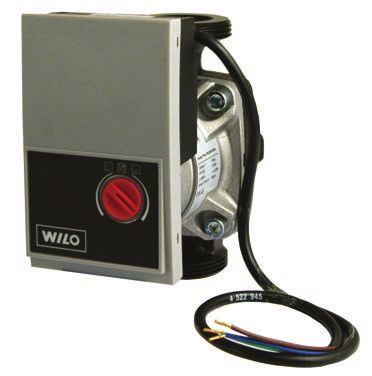
SAFETY WARNINGS - AVVERTENZE PER LA SICUREZZA

Read this manual carefully before installing and/or using the               Le g g e re co n at te n z i o n e q u e s to l i b re t to p r i m a
equipment and keep it in an accessible place.                               dell’installazione e/o dell’uso dell’apparecchiatura e
This equipment constitutes a component which is part of                     conservarlo in un luogo accessibile.
complex installations: it is the responsibility of the electrical           La presente apparecchiatura costituisce un componente che
installer to draw up the general diagram of the system and                  fa parte di installazioni complesse: è compito dell’impiantista
the electrical connections outside the equipment.                           elettrico redigere lo schema generale dell’impianto e dei
The manufacturer’s technical office can be contacted on the                 collegamenti elettrici esterni all’apparecchiatura.
numbers shown on the back of this manual for queries or                     L’ufficio tecnico del Costruttore si rende disponibile
special technical requests.                                                 ai numeri indicati sul retro del presente libretto per
                                                                            consulenze o richieste tecniche particolari.

•          CAUTION                                                          •          ATTENZIONE
    Installation and maintenance must only be carried out by                    L’installazione e la manutenzione vanno eseguiti solo da
    qualified personnel.                                                        personale qualificato.
    The hydraulic and electrical systems and the places where                   Gli impianti idraulici, elettrici ed i locali di installazione
    the equipment is to be installed must comply with the                       delle apparecchiature devono rispondere alle norme di
    safety, accident prevention and fire prevention standards                   sicurezza, antinfortunistiche e antincendio in vigore nel
    in force in the country of use.                                             Paese di utilizzo.

• It is essential to connect the equipment to an effective earthing         • E’ indispensabile collegare l’apparecchiatura ad un efficace
  system and include it in an equipotential system whose effec-               impianto di terra e includerla in un sistema equipotenziale
  tiveness.                                                                   la cui efficacia deve ottemperare alle norme in vigore.

• Before making the electrical connection, ensure that the volt-            • Prima di eseguire il collegamento elettrico, accertarsi
  age and frequency shown on the data plate correspond to                     che la tensione e la frequenza riportate sulla targhetta
  those of the power supply system.                                           caratteristiche corrispondano a quelle dell’impianto
                                                                              d’alimentazione.

         GENERAL WARNINGS - AVVERTENZE GENERALI

• If, after having unpacked the equipment, any anomaly is not-              • Se dopo aver disimballato l’apparecchiatura si nota una
  ed, do not use the equipment and contact an Assistance Cen-                 qualsiasi anomalia non utilizzare l’apparecchiatura e rivolgersi
  tre authorised by the manufacturer.                                         ad un Centro di Assistenza autorizzato dal Costruttore.
• After installation, dispose of the packaging in accordance with           • Alla fine dell’installazione smaltire gli imballi secondo quanto
  the provisions of the regulations in force in the country of use.           previsto dalle normative in vigore nel Paese di utilizzo.
• Use original spare parts only: disregarding this rule invalidates         • Esigere solo ricambi originali: la mancata osservazione di
  the warranty.                                                               questa norma fa decadere la garanzia.
• The manufacturer declines all responsibility and considers the            • Il Costruttore declina ogni responsabilità nei casi seguenti:
  warranty invalid in the following cases:                                    - Non vengano rispettate le avvertenze e le norme di
   - The aforementioned warnings and safety regulations, in-                      sicurezza sopra indicate, comprese quelle vigenti nei paesi
       cluding those in force in the country of installation, are not             di installazione.
       respected.                                                             - Mancata osservanza delle indicazioni segnalate nel
   - The information given in this manual is disregarded.                         presente manuale.
   - There is damage or injury to people, animals or objects, re-             - Danni a persone, animali o cose, derivanti da una errata
       sulting from incorrect installation and/or improper use of                 installazione e/o uso improprio di prodotti e attrezzature.
       the products and equipment..                                           - Inesattezze o errori di stampa e trascrizione contenuti nel
   - Inaccuracies or printing and transcription errors are con-                   presente manuale.
       tained in this manual.                                               • Il Costruttore, inoltre, si riserva il diritto di cessare la
• The manufacturer also reserves the right to cease production                produzione in qualsiasi momento e di apportare tutte le
  at any time and to make all the modifications which it consid-              modifiche che riterrà utili o necessarie senza obbligo di
  ers useful or necessary without any obligation to give notice.              preavviso.

                                                                        3
DISPOSAL - SMALTIMENTO

             In accordance with the provisions of the following                             In base a quanto previsto dalle seguenti direttive
             European directives 2011/65/EU, 2012/19/EU                                     europee 2011/65/UE, 2012/19/UE e 2003/108/
             and 2003/108/EC, regarding reducing the use of                                 CE, relative alla riduzione dell’uso di sostanze
             hazardous substances in electrical and electronic                              pericolose nelle apparecchiature elettriche ed
             equipment, in addition to waste disposal.                                      elettroniche, nonché allo smaltimento dei rifiuti.

The crossed out wheelie bins symbol on the equipment indicates                 Il simbolo del cassonetto barrato riportato sull’apparecchiatura
that, at the end of its useful life, the product must be collected             indica che il prodotto alla fine della propria vita utile deve essere
separately from general waste.                                                 raccolto separatamente dagli altri rifiuti.
Therefore, at the end of its useful life, the user must take the               L’utente dovrà, pertanto, conferire l’apparecchiatura giunta
equipment to a designated electrical and electronic waste                      a fine vita agli idonei centri di raccolta differenziata dei rifiuti
collection point , or return it to the dealer that, against the purchase       elettronici ed elettrotecnici, oppure riconsegnarla al rivenditore
of an equivalent appliance, it is obliged to collect the product for           che, a fronte di acquisto di apparecchio equivalente, è tenuto
disposal free of charge.                                                       al ritiro gratuito del prodotto da smaltire.
Appropriate differentiated waste collection for subsequent                     L’adeguata raccolta differenziata per l’avvio successivo
recycling, treatment and environment-friendly disposal of                      dell’apparecchiatura dismessa al riciclaggio, al trattamento e allo
the discarded equipment helps preventing possible negative                     smaltimento ambientale compatibile contribuisce ad evitare
environmental and health effects and encourages recycling of the               possibili effetti negativi sull’ambiente e sulla salute e favorisce
component materials of the equipment.                                          il riciclo dei materiali di cui è composta l’apparecchiatura.
Illegal disposal of the product by the user entails the application            Lo smaltimento abusivo del prodotto da parte dell’utente
of sanctions provided by the regulations in force.                             comporta l’applicazione delle sanzioni previste dalla vigente
                                                                               normativa in materia.

         NECESSARY EQUIPMENT AND PPD - ATTREZZATURA E D.P.I. NECESSARI

                                                                           4
INDEX - INDICE

      Description                                          Descrizione                                        Pag.
      Safety warnings                                      Avvertenze per la sicurezza                         3
      General warnings                                     Avvertenze generali                                 3
      Disposal                                             Smaltimento                                         4
      Necessary equipment and PPD                          Attrezzatura e D.P.I. necessari                     4
      Preliminary operations                               Operazioni preliminari                              6
 1    Description                                          Descrizione                                         7
 2    Content packaging                                    Contenuto imballo                                   7
2.1   Description of the equipment components              Descrizione parti apparecchiatura                   8
2.2   Connection description                               Descrizione attacchi apparecchiatura                9
 3    Installation                                         Installazione                                      10
3.1   Unpacking                                            Disimballo                                          10
3.2   Overall dimensions                                   Dimensioni di ingombro                              10
3.3   Possible installations                               Installazioni possibili                             11
3.4   Wall installation                                    Installazione a parete                              12
3.5   External wall installation                           Installazione esterna a parete                      14
3.6   Boiler placement with embedded cabinet               Predisposizione caldaia con armadio incassato       15
3.7   Boiler placement with external cabinet               Predisposizione caldaia con armadio esterno         15
3.8   Hydraulic connections                                Collegamenti idraulici                              16
3.9   Electrical connection setup                          Predisposizione collegamenti elettrici              17
3.10 General electrical connection diagram                 Schema di collegamento elettrico generale           18
3.11 Heating consent                                       Consenso riscaldamento                              18
3.12 Electrical connections with LT modules                Collegamenti elettrici con moduli BT                19
3.13 Electrical connections with HT modules                Collegamenti elettrici con moduli AT                20
3.14 Connections with external actuators                   Collegamenti con attuatori esterni all’unità        21
3.15 Wiring connection for optional radiator pump          Collegamenti elettrico pompa opzionale radiatori    21
3.16 Cabinet door earth connection                         Collegamento a terra della porta armadietto         22
 4    Start-up                                             Messa in funzione                                  23
4.1   Main flow rate adjustment                            Regolazione portata principale                      23
 5    Component technical data                             Dati tecnici dei componenti                        24
5.1   Safety control unit                                  Centralina elettronica di sicurezza                 24
5.2   Mixing valve                                         Valvola miscelante                                  27
5.3   M7410E Servomotor                                    Servomotore M7410E                                  28
5.4   Electrothermal head with microswitch                 Testina elettrotermica con micro                    29
5.5   VZR zone valve for MTR                               Valvola di zona VZR per MTR                         30
5.6   MVZ actuator for MTR                                 Attuatore MVZ per MTR                               31
      Grundfos UMPXL 25-105 low temperature side electronic Circolatore elettronico lato bassa temperatura
5.7                                                                                                            32
      circulator                                            Grundfos UMPXL 25-105
5.8   Self-adjusting Electronic Circulation Pump           Circolatore elettronico autoregolante               41
5.9   HE electronic circulation pump                       Circolatore elettronico HE                          46
 6    Accessories                                          Accessori                                          52
 7    Electrical diagrams                                  Schemi elettrici                                   53

                                                       5
PRELIMINARY OPERATIONS - OPERAZIONI PRELIMINARI

TESTING, TRANSPORT AND UNPACKAGING                                      ISPEZIONE, TRASPORTO E DISIMBALLO

Upon receipt, check immediately that the packaging is intact:           All’atto del ricevimento verificare immediatamente l’integrità
the machine has left the factory in perfect working order and any       dell’imballo: la macchina ha lasciato la fabbrica in perfetto stato,
damage must be notified to the carrier immediately and noted on         eventuali danni dovranno essere immediatamente contestati
the Delivery Sheet before it is countersigned.                          al trasportatore ed annotati sul Foglio di Consegna prima di
Within 8 days, the customer must notify the manufacturer of the         controfirmarlo.
extent and type of the damage noted, making a written report:           Il Cliente, entro 8 giorni, deve avvisare il Costruttore sull’entità
always take note of the serial number which can be found on the         e la tipologia dei danni rilevati compilando un rapporto scritto:
plate affixed to the machine.                                           riportare sempre anche il numero di matricola rilevabile dalla
                                                                        targhetta posta a bordo macchina.

                                   2a                     2b

                                                OK!
           1
                                                                                                  RDZ
                                                                                       3b
                                                 3a
                                                                                                        6
                                                                                         within 8 days
                                                                                         entro 8 giorni

                                                                                                              4

                                          Kg
                                        46 Kg
                                      N
                                    MI X 56
                                     MA

                                                                            5

        The unit packaging                                                                                           L’imballo dell’unità
must be removed with care,                                                                                  deve essere rimosso con cura
ensuring that the machine is not                                                                            evitando di arrecare possibili
damaged.                                                                                                    danni alla macchina.
The materials which make up                                                                                 I materiali che costituiscono
the packaging are different:                                                                                l’imballo sono di natura diversa:
wood, cardboard, nylon etc.                                                                                 legno, cartone, nylon, ecc.
Store them separately and                                                                                   Conservarli separatamente e
deliver them for disposal or,                                                                               consegnarli per lo smaltimento
where appropriate, recycling,                                                                               o l’eventuale riciclaggio, alle
to the relevant companies, thus                                                                             aziende preposte allo scopo
reducing the environmental                                                                                  e r i d u r n e co s ì l ’i m p at to
impact.                                                                                                     ambientale.
                                                                    6
1      DESCRIPTION - DESCRIZIONE

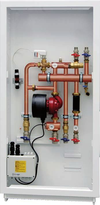
             MTR VJ 0-10 module is a pre-assembled mini-                                   Il Modulo MTR VJ 0-10 è una mini centrale termica premontata
               thermal unit, which is used to regulate underfloor                          per la regolazione di un impianto a pavimento e a radiatori
                  systems and radiators. It includes: a cabinet                            completa di armadietto in acciaio verniciato a polveri con
                  with adjustable feet, made of steel painted with                         piedini regolabili, staffe, portina bianca a finire con serratura.
                  powders, brackets, a white door with lockset,                            Valvola di miscelazione a 3 vie con by-pass incorporato,
                  a three-way mixing valve with integrated by-                             servomotore analogico 0-10, valvole di non ritorno, detentore
                  pass, an analogue motor 0-10, check valves,                              micrometrico di taratura, valvole a sfera con bocchettoni,
                  a micrometric balancing lockshield valve, ball                           termometri a quadrante, circolatore elettronico a portata e
 valves with tail pieces, thermometers with scale labels, a UMPXL                          prevalenza variabile mod. UMPXL 25-105, valvole di sfiato e
25-105 electric circulation pump with variable pressure and                                carico-scarico impianto, termostato di sicurezza elettronico,
flow rate, vent valves and fill/drain valves, a safety electronic                          connettore per l’allacciamento elettrico e impianto cablato
thermostat, a connector to the electrical system and a wired                               comprensivo di cablatura per le valvole di zona della bassa
system both for low-temperature zone valves and high-                                      temperatura e le testine elettrotermiche dell’alta temperatura.
temperature thermo-electric actuators. It can be combined with                             Adatto ad essere comandato da una centralina esterna mod.
RDZ Wi controllers.                                                                        RDZ Wi.

 2      CONTENT PACKAGING - CONTENUTO IMBALLO

The package contains:
La confezione contiene:
Rif.   Description                                                                         Descrizione
 a     MTR VJ                                                                              MTR VJ
 b     Painted frame                                                                       Telaio verniciato
 c     Painted door                                                                        Porta verniciata
 d     Plaster protection cover                                                            Coperchio di protezione intonaci
 e     Allen key of 5 mm                                                                   Chiave a brugola da 9 mm
  f    Cabinet lock                                                                        Serratura per armadietto
 g     Fixing screws for plaster protection                                                Viti per fissaggio protezione intonaco
 h     Declaration of conformity                                                           Dichiarazione di conformità
  i    MTR technical manual                                                                Manuale tecnico MTR

                a                                                                                                                 e
                                                                                   b

                                                                                                      c
                                                                                                                        d         fd

                                                        150
                                            100          200

                                           50           250
                                            0     bar

                                                                                                                                  g

                                                                            150
                                                                100          200

                                                               50           250
                                                                0     bar

                                    150
                        100          200

                       50           250
                        0     bar

                                                                                                                              h

                                                                                                                        i

                                                                                       7
DESCRIPTION OF THE EQUIPMENT COMPONENTS
2.1
       DESCRIZIONE PARTI APPARECCHIATURA

Appliance parts key
Legenda parti apparecchiatura
Rif.   Description                                                                                               Descrizione
 A     Servomotor                                                                                                Servomotore
 B     Regulation holder                                                                                         Detentore di regolazione
 C     Discharge cocks                                                                                           Rubinetto di scarico
 D     Nippers                                                                                                   Tronchetto
 E     Cabinet                                                                                                   Armadietto
 F     Hight temperature thermometer                                                                             Termometro alta temperatura
 G     Control unit                                                                                              Centralina di controllo
 H     Adjustment feet                                                                                           Piedini di regolazione
 I     Supply and consent plugs                                                                                  Spinotti di alimentazione e consenso
 J     Low temperature thermometer                                                                               Termometro bassa temperatura
 K     UPMXL circulator                                                                                          Circolatore UPMXL
 L     Servomotor and delivery probe plug                                                                        Spinotto servomotore e sonda mandata
 M     Mixing valve                                                                                              Valvola miscelatrice
 N     DICF module                                                                                               Modulo DICF
 O     BT2 / BT3 module                                                                                          Modulo BT2 / BT3
 P     HT2 / HT3 module                                                                                          Modulo HT2 / HT3
 Q     Optional ELECTRONIC circulation pump                                                                      Circolatore ELETTRONICO opzionale
 R     Anti-condensation insulation for MTR                                                                      Isolamento anticondensa per MTR

                                         A                                                                                                  OPTIONAL

                                                                                                                                                        N

                                                                                                                                                        O
              M                                                                                                            B
                                                                             30
                                                                        20        40
                                                                             °C
                                                                   10              50

                                                                        0         60

                 L
                                                                                                                          C
                                                                                                                                                        P
                 K                                                                                                        D
                                                                                                                           E

                 J                                                                                                         F                            Q
                                                        30
                                                   20        40                                   30
                                                        °C                                   20        40
                                              10              50                                  °C
                                                                                        10              50
                                                   0         60
                                                                                             0         60

                 I

                                                                                                                                                        R

                 H
                                  G
                                                                                                             8
DESCRIPTION OF THE CONNECTIONS
 2.2
        DESCRIZIONE ATTACCHI APPARECCHIATURA

 Connection keys
 Legenda attacchi apparecchiatura
                                                                                                                                            Connections
 Rif.   Description                                                                    Descrizione
                                                                                                                                              Attacchi
  A     Boiler/chiller flow                                                            Mandata da caldaia / chiller                            M 3/4”
   B    Boiler/chiller return                                                          Ritorno a caldaia / chiller                             M 3/4”
  C     High temperature flow *                                                        Mandata alta temperatura *                              F 3/4”
  D     High temperature return *                                                      Ritorno alta temperatura *                              F 3/4”
   E    Low temperature flow *                                                         Mandata bassa temperatura *                              F 1”
   F    Low temperature return *                                                       Ritorno bassa temperatura *                              F 1”

N.B. See chapter “Accessories” if using optional elements such                                    N.B. Nel caso di utilizzo di accessori opzionali, quali HT2,
as: HT2, HT3, BT2, BT3 and DICF.                                                                  HT3, BT2, BT3 e DICF consultare capitolo “Accessori”.

                                                                                                                              A

                                                                                                                               B
                                                                                  30
                                                                             20        40
                                                                                  °C
                                                                        10              50

                                                                             0         60

                                                             30
                                                        20        40                                           30
                                                             °C                                           20        40
                                                   10              50                                          °C
                                                                                                     10              50
                                                        0         60
                                                                                                          0         60

                                        F                                    E                      D                     C
                                                                                              9
3     INSTALLATION - INSTALLAZIONE

3.1   UNPAKING - DISIMBALLO

1                                                                                                           2
                                                                                                                                                                                 1

                                                                                                   1
                                              150
                                  100          200

                                 50           250
                                  0     bar

                                                                                                                                                      150
                                                                                                                                          100          200

                                                                                                                                         50           250
                                                                                                                                          0     bar

                                                                  150
                                                      100          200

                                                     50           250
                                                      0     bar

                          150
              100          200

             50           250
              0     bar

                                                                                                                      100

                                                                                                                     50
                                                                                                                      0     bar
                                                                                                                                  150
                                                                                                                                   200

                                                                                                                                  250
                                                                                                                                                              100

                                                                                                                                                             50
                                                                                                                                                              0     bar
                                                                                                                                                                          150
                                                                                                                                                                           200

                                                                                                                                                                          250

                                                                                                                                                                                             2

                                                                                                                                                                                     2
                                                                         c                                                                                                               b

3.2   OVERALL DIMENSIONS - DIMENSIONI DI INGOMBRO

                                                                                                       60
                                                                             min. 136 - max. 144

                                                                                                                18

                                                                                                       10
3.3   POSSIBLE INSTALLATIONS - INSTALLAZIONI POSSIBILI

                                                             X Y
                               X

                                                         1

                                                             X Y
                                X

                                DRY                          DRY

       2                                   3

                                          11
3.4       WALL INSTALLATION - INSTALLAZIONE A PARETE

1                                                                                          3

                                                                                                                                                                   2

                                                                                                                                        150
                                                                                                                            100          200

                                                                                                                           50           250
                                                                                                                            0     bar

                                                                                                                                                            150
                                                                                                                                                100          200

                                                                                                                                               50           250
                                                                                                                                                0     bar

                                                                                                                    150
                                                                                                        100          200

                                                                                                       50           250
                                                                                                        0     bar

                                                                                                                                                                       d

                                                                                           1

2                                                                                          4
      1                                                                                        1

                                                           150
                                               100          200

                                              50           250
                                               0     bar

               3                       150
                                                                   100

                                                                  50
                                                                   0     bar
                                                                               150
                                                                                200

                                                                               250

                           100          200

                          50           250
                           0     bar

                                                                                                   2

                         2

                                                                                      12
5                                                                                7
                                                                                                                                                         4

                                                                                                                          150
                                                                                                              100          200

                                                                                                             50           250
                                                                                                              0     bar

        1
                                                                                                                                              150
                                                                                                                                  100          200

                                                                                                                                 50           250
                                                                                                                                  0     bar

                                                                                                      150
                                                                                          100          200

                                                                                         50           250
                                                                                          0     bar

        1                                                                            3                                                               1       2

6

    2
                                             150
                                 100          200

                                50           250
                                 0     bar

                                                                 150
                                                     100          200

                                                    50           250
                                                     0     bar

                         150
             100          200

            50           250
             0     bar

                                                                        1

                                                                            13
3.5     EXTERNAL WALL INSTALLATION - INSTALLAZIONE ESTERNA A PARETE

1                                                                                                                                                       3
    3
                                                                                                                                                                                                                                1
                                                                                                                                                                                                                                    6

                                                                                                                                                                                                 150
                                                                                                                                                                                     100          200

                                                                                                                                                                                    50           250
                                                                                                                                                                                     0     bar

                                                                                                                    150
                                                                                                        100          200

                                                                                                       50           250

                                                                                                                                                            2
                                                                                                        0     bar

                                                                                                                                                                                                                         150
                                                                                                                                                                                                             100          200

                                                                                                                                                                                                            50           250
                                                                                                                                                                                                             0     bar

                                                                                                                                                                             150
                                                                                                                                                                 100          200

                                                                                                                                                                50           250
                                                                                                                                                                 0     bar

                                                                                                                                        150
                                                                                                                            100          200

                                                                                                                           50           250
                                                                                                                            0     bar

                                                                                                150

                                                                                                                                                                                                        5
                                                                                    100          200

                                                                                   50           250
                                                                                    0     bar

                  2

                                                                                                                                                                                                                                3       4
                                                                                                                                               1

2

                                                        150
                                            100          200

                                           50           250
                                            0     bar

                                                                            150
                                                                100          200

                                                               50           250
                                                                0     bar

                                    150
                        100          200

                       50           250
                        0     bar

                                                                                                                                                   14
BOILER SETUP WITH EMBEDDED CABINET                                                BOILER SETUP WITH EXTERNAL CABINET
3.6                                                                               3.7
      CALDAIA CON ARMADIO INCASSATO                                                     CALDAIA CON ARMADIO ESTERNO

                                                                                                                                       150
                                                                                                                           100          200

                                                                                                                          50           250
                                                                                                                           0     bar

                                                  150
                                      100          200

                                     50           250
                                      0     bar

                                                                                                                                                           150
                                                                                                                                               100          200

                                                                                                                                              50           250
                                                                                                                                               0     bar

                                                                      150
                                                          100                                                      150
                                                                       200
                                                                                                       100          200
                                                         50           250
                                                          0                                           50           250
                                                                bar
                                                                                                       0     bar

                              150
                  100          200

                 50           250
                  0     bar

                                                                             15
3.8    HYDRAULIC CONNECTIONS - COLLEGAMENTI IDRAULICI

MTR VJ with HT3 module (optional electrothermal heads) and BT2                                                                                                                                            Modulo MTR VJ con modulo HT3 (testine elettriche optional)
module (Example)                                                                                                                                                                                          e BT2 (Esempio).

                                                                                                                                                                                               30
                                                                                                                                                                                          20        40
                                                                                                                                                                                               °C
                                                                                                                                                                                     10              50

                                                                                                                                                                                          0         60

                                                                                                                                                                          30
                                                                                                                                                                     20        40                                          30
                                                                                                                                                                          °C                                          20        40
                                                                                                                                                                10              50                                         °C
                                                                                                                                                                                                                 10              50
                                                                                                                                                                     0         60
                                                                                                                                                                                                                      0         60

                RDZ
                                                                                                                                30
                                                                                                                           20        40
                                                                                                                                °C
                                                                                                                      10              50

                                                                                                                           0         60

                            10   10   10   10   10   10   10   10   10   10   10   10   10   10   10   10   10   10
                             8    8    8    8    8    8    8    8    8    8    8    8    8    8    8    8    8    8
                             6    6    6    6    6    6    6    6    6    6    6    6    6    6    6    6    6    6
                             4    4    4    4    4    4    4    4    4    4    4    4    4    4    4    4    4    4
                             2    2    2    2    2    2    2    2    2    2    2    2    2    2    2    2    2    2
                             0    0    0    0    0    0    0    0    0    0    0    0    0    0    0    0    0    0

                      RDZ
                                                                                                                                                     30
                                                                                                                                                20        40
                                                                                                                                                     °C
                                                                                                                                           10              50

                                                                                                                                                0         60

                                                                                                                                                                                     16
3.9

                                                                                                                                                                                                                                                                module (Example)
                                                                                                                                                                                                                                 KEY - LEGENDA
                                                                                                                                                                                                                                 A-B = Control Unit
                                                                                                                                                                                                                                       Centralina
                                                                                                                                                                                                                                 C= Boiler power supply
                                                                                                                                                                                                                                    Alimentazione caldaia
                                                                                                                                                                                                                                 D= Chiller power supply
                                                                                                                                                                                                                                    Alimentazione chiller
                                                                                                                                                                                                                                 E= MTR power supply
                                                                                                                                                   150
                                                                                                                                                       200

                                                                                                                                           50100 250
                                                                                                                                            0   vbar

                                                                                                                                                             50100 250
                                                                                                                                                              0   bar
                                                                                                                                                                        150
                                                                                                                                                                         200

                                                                                                                                                                        aa
                                                                                                                                                                                                                                    alimentazione MTR
                                                                                                                                                                                                                                 F= Dehumidifier power supply
                                                                                                                                                                                                                                    Alime. Deumidificatore

                                                                                                                                                                                                                        F
                                                                                                                                                                                                                    W
                                                                                                                                                                                                                                                                MTR VJ with HT3 module (optional electrothermal heads) and BT2

                                                                                                                                                                               RN
                                                                                                                                                                                        150
                                                                                                                                                                                            200

                                                                                                                                                                                50100 250
                                                                                                                                                                                 0   vbar

17
                                                                                                                                                                                                             150
                                                                                                                                                                                                              200

                                                                                                                                                                                                  50100 250
                                                                                                                                                                                                   0   bar
                                                                                                                                                                                                                                                                                                                                 ELECTRICAL CONNECTION SETUP (EXAMPLES)

                                                                                                                                    C

                                                                                                                                                                                                                            U%

                                                                                                             150
                                                                                                              200

                                                                                                    50100   250
                                                                                                     0 bar
                                                                                                                                    EB
                                                                                                                                       A
                                                                                                                             150
                                                                                                                              200

                                                                                                                    50100   250
                                                                                                                     0 bar
                                                                                                                                                                                                                                                                e BT2 (Esempio).

                                                                                             150
                                                                                              200

                                                                                    50100   250
                                                                                     0 bar
               F
                       E                                       2x
                               D                                 0,7
                                         C                          5
                                             B
                                                 A
                                                                                D
      IN
     DEU T.
        MD INT
                                                                    T-E
            .     .                                                     X
              MT                                                            T
                                                                                                                                                                                                                                                                                                                                 PREDISPOSIZIONE COLLEGAMENTI ELETTRICI (ESEMPI INDICATIVI)

                 R     IN
                      REF T.
                         RIG   I
                            . CANT.
                                LDA
                                    IA

                                                     ES                 SU
                                                       T                    D

                                                     NO                  OV
                                                          RD               ES
                                                                              T
                                                                                                                                                                                                                                                                Modulo MTR VJ con modulo HT3 (testine elettriche optional)
GENERAL WIRING CONNECTION DIAGRAM
3.10
        SCHEMA DI COLLEGAMENTO ELETTRICO GENERALE

     CONNECT ACCORDING TO THE DIAGRAM AND RESPECT                       COLLEGARE COME DA SCHEMA E RISPETTARE LA
THE PHASE - NEUTRAL POLARITY.                                      POLARITÀ FASE - NEUTRO.

N/   / T = Tension 230 Vac - 50 Hz                                                          230V-50Hz Mains power supply
N/   / T = Alimentazione da rete 230 Vac - 50 Hz                                            Alimentazione di rete 230V-50Hz

                                                                                                     N

                                                                                                     L

                                                                    3-pole movable socket “a”
                                                                   Spinotto volante “A” a 3 poli
                                 Chiller consent
                                Consenso chiller
                                                              4-pole movable socket “B”
                                                              Spinotto volante “B” a 4 poli

                                                                    Boiler consent
                                                                   Consenso caldaia

                           Servomotor
                          Servomotore
                                                            24 Vac
                                                             COM

                                                              Y

                                                            1 2 3
                                                             4 5
                                                                                  Delivery probe
                                                                                  Sonda di mandata

3.11 HEATING CONSENT - CONSENSO RISCALDAMENTO

                                     JUMPER (supplied as standard)
                                        PONTICELLO (di serie)
                                      32 33 34 35

                                                    44 45   1 2   3   4 5   6 7

                                                              18
3.12 ELECTRICAL CONNECTIONS WITH LT MODULES - COLLEGAMENTI ELETTRICI CON MODULI BT

CONNECTION OF 2-3 LT ROOM THERMOSTATS WITH 2-3                                                                                COLLEGAMENTO DA 2-3 TERMOSTATI AMBIENTE BT
ACTUATORS                                                                                                                     CON 2-3 ATTUATORI

                                                                                                                                                                                         8    Phase / Fase
                                                       ZONA 3                           ZONA 2                          ZONA 1

                                  38 39 40 41 42 43
                                                                                                                                                                                         9    Neutral/neutro
                                                      20 21 22 23               24 25 26 27                            28 29 30 31
                                                                                                                                                                                         10   Micro
ZONE 3                                                                                                                                                                                   11   Micro
ZONA 3
                                                       ZONA 3                           ZONA 2                          ZONA 1                                           ZONE VALVE 1
                                                      8 9 10 11                 12 13 14 15                            16 17 18 19                                      VALVOLA ZONA 1
ZONE 2                            32 33 34 35 36 37
                                                                                                                                                                                         12   Phase / Fase
ZONA 2                                                                                                                                                                                   13   Neutral/neutro
                                                                                                                                                                         ZONE VALVE 2    14   Micro
                                                                                                                                                                        VALVOLA ZONA 2   15   Micro
ZONE 1
ZONA 1
                                                                    1 2                  3   4 5                        6 7                                                              16   Phase / Fase
                                                                                                                                                                         ZONE VALVE 3
                                                                                                                                                                        VALVOLA ZONA 4   17   Neutral/neutro
                                                                                                                                                                                         18   Micro
                                                                                                                                                                                         19   Micro

 CONNECTION OF ONE THERMOSTAT                                                                                                  COLLEGAMENTO DI UN SOLO TERMOSTATO PER LA
 TO CONTROL ONE ZONE                                                                                                           GESTIONE DI UNA SINGOLA ZONA
(MTR VJ with RDZ actuators externally installed) .                                                                            (MTR VJ con attuatori RDZ installati esternamente).
Without jumper the module does not work.                                                                                      Senza ponticello l’apparecchiatura non funziona.

                                                                                                                       ZONA 3           ZONA 2            ZONA 1
                                                                    38 39 40 41 42 43

                                                                                                             20 21 22 23               24 25 26 27       28 29 30 31

                                                                                                                       ZONA 3           ZONA 2            ZONA 1
                                                                                                                 8 9 10 11             12 13 14 15       16 17 18 19
                                                                    32 33 34 35 36 37

                ZONE 1
                ZONA 1
                                                                                                                                     1 2   3   4 5        6 7

                                                                                                                                                     JUMPER
                                                                                                                                      (supplied as standard)
                                                                                                                                               PONTICELLO
                                                                                                                                                    (di serie)

 CONNECTION OF MANY THERMOSTATS                                                                                                COLLEGAMENTO DI PIÙ TERMOSTATI PER LA GESTIONE
 TO CONTROL DIFFERENT ZONES                                                                                                    DI PIÙ ZONE
(MTR VJ with RDZ actuators externally installed)                                                                              (MTR VJ con attuatori RDZ installati esternamente).
Without jumper the module does not work .                                                                                     Senza ponticello l’apparecchiatura non funziona.

                                                                                                                                      ZONA 3          ZONA 2            ZONA 1
                                                                                                   38 39 40 41 42 43

                                                                                                                                     20 21 22 23     24 25 26 27       28 29 30 31
                     F N
      ZONE 2
      ZONA 2
                                                                                                                                      ZONA 3          ZONA 2            ZONA 1

                     F N                                                                                                             8 9 10 11       12 13 14 15       16 17 18 19
      ZONE 2
                                                                                                   32 33 34 35 36 37

      ZONA 2

                     F N
      ZONE 1
      ZONA 1
                                                                                                                                                   1 2    3   4 5       6 7

                                                                                                                                                              JUMPER
                                                                                                                                               (supplied as standard)
                                                                                                                                                        PONTICELLO
                                                                                                                                                             (di serie)
                                                                                                                         19
3.13 ELECTRICAL CONNECTIONS WITH HT MODULES - COLLEGAMENTI ELETTRICI CON MODULI AT

CONNECTION OF 2-3 HT ROOM THERMOSTATS WITH 2-3                                                                       COLLEGAMENTO DA 2-3 TERMOSTATI AMBIENTE AT
ACTUATORS                                                                                                            CON 2-3 ATTUATORI

                                                                                                                                                                                 20   Phase / Fase
                                                ZONA 3                           ZONA 2                        ZONA 1

                           38 39 40 41 42 43
                                                                                                                                                                                 21   Neutral/neutro
                                               20 21 22 23                 24 25 26 27                        28 29 30 31
                                                                                                                                                                                 22   Micro
ZONE 3                                                                                                                                                                           23   Micro
ZONA 3
                                                ZONA 3                           ZONA 2                        ZONA 1                                            ZONE HEAD 1
                                               8 9 10 11                  12 13 14 15                         16 17 18 19                                       TESTINA ZONA 1
ZONE 2                     32 33 34 35 36 37
                                                                                                                                                                                 27   Phase / Fase
ZONA 2                                                                                                                                                                           25   Neutral/neutro
                                                                                                                                                                 ZONE HEAD 2     26   Micro
                                                                                                                                                                TESTINA ZONA 2   27   Micro
ZONE 1
ZONA 1
                                                              1 2                 3   4 5                      6 7                                                               28   Phase / Fase
                                                                                                                                                                 ZONE HEAD 3
                                                                                                                                                                TESTINA ZONA 4   29   Neutral/neutro
                                                                                                                                                                                 30   Micro
                                                                                                                                                                                 31   Micro

 CONNECTION OF ONE THERMOSTAT TO CONTROL ONE                                                                          COLLEGAMENTO DI UN SOLOS TERMOSTATO PER LA
 ZONE                                                                                                                 GESTIONE DI UNA SINGOLA ZONA
(MTR VJ with RDZ actuators externally installed).                                                                    (MTR VJ con attuatori RDZ installati esternamente).
Without jumper the module does not work.                                                                             Senza ponticello l’apparecchiatura non funziona.

                                                                                                              ZONA 3           ZONA 2            ZONA 1
                                                             38 39 40 41 42 43

                                                                                                    20 21 22 23               24 25 26 27       28 29 30 31

                                                                                                              ZONA 3           ZONA 2            ZONA 1
                                                                                                        8 9 10 11             12 13 14 15       16 17 18 19
                                                             32 33 34 35 36 37

              ZONE 1
              ZONA 1
                                                                                                                            1 2   3   4 5        6 7

                                                                                                                                            JUMPER
                                                                                                                             (supplied as standard)
                                                                                                                                      PONTICELLO
                                                                                                                                           (di serie)

 CONNECTION OF MANY THERMOSTATS TO CONTROL                                                                            COLLEGAMENTO DI PIÙ TERMOSTATI PER LA GESTIONE
 DIFFERENT ZONES                                                                                                      DI PIÙ ZONE
(MTR VJ with RDZ actuators externally installed).                                                                    (MTR VJ con attuatori RDZ installati esternamente).
Without jumper the module does not work .                                                                            Senza ponticello l’apparecchiatura non funziona.

                                                                                                                             ZONA 3          ZONA 2            ZONA 1
                                                                                          38 39 40 41 42 43

                                                                                                                            20 21 22 23     24 25 26 27       28 29 30 31
                  F N
     ZONE 2
     ZONA 2
                                                                                                                             ZONA 3          ZONA 2            ZONA 1

                  F N                                                                                                       8 9 10 11       12 13 14 15       16 17 18 19
     ZONE 2
                                                                                          32 33 34 35 36 37

     ZONA 2

                  F N
     ZONE 1
     ZONA 1
                                                                                                                                          1 2    3   4 5       6 7

                                                                                                                                                     JUMPER
                                                                                                                                      (supplied as standard)
                                                                                                                                               PONTICELLO
                                                                                                                                                    (di serie)
                                                                                                               20
CONNECTIONS WITH EXTERNAL ACTUATORS
 3.14
          COLLEGAMENTI CON ATTUATORI ESTERNI ALL’UNITÀ

     CONNECT ACCORDING TO THE DIAGRAM AND RESPECT                          COLLEGARE COME DA SCHEMA E RISPETTARE LA
THE POLARITY (PHASE - NEUTRAL).                                       POLARITA’ FASE - NEUTRO.

ELECTROTHERMAL HEADS WITH MICROSWITCH                                  TESTINE ELETTROTERMICHE CON MICRO

 F

                     Thermostat                                  Thermostat
                T1   Termostato                         T2       Termostato

                                                                                          32 33 34 35 36 37            38 39 40 41 42 43

           Actuator without micro Actuator with micro Actuator with micro
           Testina con micro      Testina con micro Testina con micro
 N

                                                                                                                                 20
                                                                                                                  8
ELECTRO-THERMAL HEADS WITH RELAY                                       TESTINE ELETTROTERMICHE CON RELE’

     F

                            Thermostat
         TA1                Termostato   TA2
 Thermostat
 Termostato
                       k1      k1                        k2       k2
                                     Double-
               k1               exchage relay   k2
                                 Relè doppio
     Double-                        scambio                                               32 33 34 35 36 37           38 39 40 41 42 43
exchage relay
 Relè doppio
    scambio                  Actuator without micro           Actuator without micro
                             Testine senza micro              Testine senza micro
     N                                                                                                                           20
                                                                                                                  8
                                                                                                                      ZONA 3

                                                                                                                                      ZONA 3
          WIRING CONNECTION FOR OPTIONAL RADIATOR PUMP
 3.15
          COLLEGAMENTI ELETTRICO POMPA OPZIONALE RADIATORI

                         ZONA 1
                                                                               OPTIONAL
                       16 17 18 19                                                 PUMP
                                                                                 POMPA
                                                                              OPZIONALE

                         6 7

                                                                                                          0
                                                                                                     15
                                                                                                 0            0
                                                                                               10     20

                                                                 21
3.16 CABINET DOOR EARTH CONNECTION - COLLEGAMENTO A TERRA DELLA PORTA ARMADIETTO

                                                             150
                                                 100          200

                                                50           250
                                                 0     bar

                                                                                 150
                                                                     100          200

                                                                    50           250
                                                                     0     bar

                                         150
                             100          200

                            50           250
                             0     bar

  1

                                                                                        2

                                                                                        22
4    STARTUP - MESSA IN FUNZIONE

4.1   MAIN FLOW ADJUSTMENT - REGOLAZIONE PORTATA PRINCIPALE

SYSTEM WITH HEATING ELEMENTS                                                                                                     SYSTEM WITHOUT HEATING ELEMENTS
IMPIANTO CON CORPI SCALDANTI                                                                                                     IMPIANTO SENZA CORPI SCALDANTI

                                                                                                                                                                                                                     150
                                                                                                                                                                                                         100          200

                                                                                                                                                                                                        50           250
                                                                                                                                                                                                         0     bar

                                                                                                                                  1
                                                                                    150
                                                                        100          200

                                                                       50           250
                                                                        0     bar

1                                                                                                                                                                                                                               100

                                                                                                                                                                                                                               50
                                                                                                                                                                                                                                0     bar
                                                                                                                                                                                                                                            150
                                                                                                                                                                                                                                             200

                                                                                                                                                                                                                                            250

                                                                                                                                                                                                 150
                                                                                                                                                                                     100          200

                                                                                                                                                                                    50           250
                                                                                                                                                                                     0     bar

                                                                                                        150
                                                                                            100          200

                                                                                           50           250
                                                                                            0     bar

                                                                150
                                                    100          200

                                                   50           250
                                                    0     bar

                                              PRIMARY MTR CIRCUIT PRESSURE DROP                                                                3-way valve with via "B" completely open
                                              PERDITE DI CARICO CIRCUITO PRIMARIO MTR                                                 Valvola a 3 vie con via "B" completamente aperta
                                       3500
                                                                                                                       1 GIRO

                                       3000

                                       2500
                                                                                                                                                      2 GIRI
            Perdita di carico [DaPa]
             Pressure drop [DaPa]

                                       2000
                                                                                                                                                                 4 GIRI
                                                                                                                                                                           6 GIRI
                                       1500
                                                                                                                                                                           Tutto aperto

                                       1000

                                        500

                                         0
                                          400                                              500                 600   700        800           900         1000            1100                                              1200
                                                                                                                           Flow rate [l/h]
                                                                                                                            Portata [l/h]

                                                                                                                            23
5    TECHNICAL DATA OF THE COMPONENTS - DATI TECNICI DEI COMPONENTI

5.1   SAFETY ELECTRONIC CONTROL UNIT - CENTRALINA ELETTRONICA DI SICUREZZA

                                                                                            SPECIFICATIONS

                                                                                            1) Power supply: 230 Vca - 50 Hz. (Terminals 3CN2-4CN2).
                                                                                            2) N 4 outputs via relay with voltage-free contacts.
                                                                                               3 outputs with 8A 250Vca.
                                                                                               1 output with 6A 240Vca.
                                                                                            3) Output contacts ON-OFF.
                                                      150
                                          100          200

                                         50           250
                                          0     bar

                                                                                            4) Encapsulated temperature probe with cable.
                                                                                               Connection to the terminal board with double pole cable
                                                                                            5) Adjustable safety limit, range 50-55 °C, preset at 50 °C.
                                                                                               3 °C fixed differential value. (Terminal output1CN1-2CN1).
                                                                          150
                                                              100          200

                                                             50           250
                                                              0     bar

                                  150
                      100          200

                     50           250

                                                                                            6) Integrated summer anti-seizure function.
                      0     bar

                                                                                            7) Integrated anti-freeze function.
                                                                                            8) Led indicator management.
                                                                                            9) Size 90X85 mm.

                                                                                            CARATTERISTICHE TECNICHE

                                                                                            1) Alimentazione elettrica: 230 Vca - 50 Hz. (Morsetti 3CN2-4CN2).
                                                                                            2) N. 4 uscite tramite relè con contatti liberi da tensione.
                                                                                               3 uscite da 8A 250Vca.
                                                                                               1 uscita da 6A 240Vca.
                                                                                            3) Contatti in uscita di tipo ON-OFF.
                                                                                            4) Sonda di temperatura incapsulata con cavo.
                                                                                  TR
                                                                                 M
                                                                                               Collegamento alla morsettiera con cavo bipolare.
                                                                                            5) Soglia di sicurezza regolabile, scala 50-55 °C, preimpostata 50 °C.
                                                                                               Differenziale fisso 3 °C. (Uscita sui morsetti 1CN1-2CN1).
                                                                                            6) Funzione antigrippaggio estivo integrata.
                                                                                            7) Funzione antigelo integrata.
                                                                                            8) Gestione dei led luminosi di segnalazione.
                                                                                            9) Dimensioni 90X85 mm.

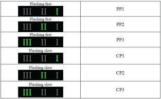
LED INFORMATION                                                                             INDICAZIONI LUMINOSE

                                                                                                     MTR

                                                                                             Luce gialla accesa: consenso dall’unità ambiente zone a
      Yellow light on: room unit consent. Consent signal
                                                                                             pavimento. Segnale di consenso all’accensione da parte del
      of the thermostat or room chrono-thermostats at the
                                                                                             termostato o crono-termostato ambiente.
      start up.
                                                                                             Luce gialla lampeggiante: termine della richiesta di
      Flashing yellow light: underfloor heating request
                                                                                             riscaldamento zone a pavimento. La centralina provvede
      ends. The control unit switches off the pump after a
                                                                                             a spegnere la pompa dopo una post-circolazione di circa
      post-circulation of about 30 seconds. Anti-seizure
                                                                                             30 secondi. Funzione antigrippaggio sulla pompa (azione
      function on the pump (every 12 hours).
                                                                                             ogni 12 ore).
      Yellow light off: the room has reached the desired
                                                                                             Luce gialla spenta: zone a pavimento in temperatura; non
      temperature; there are no requests for activation by
                                                                                             vi è richiesta di attivazione da parte del termostato o crono-
      the thermostat or room chrono-thermostats.
                                                                                             termostato ambiente.

                                                                                       24
Luce verde accesa: consenso dall’unità ambiente zone a
         Green light on: radiator unit consent. Consent signal
                                                                             radiatori. Segnale di consenso all’accensione da parte del
         of the thermostat or room chrono-thermostats at the
                                                                             termostato o cronotermostato ambiente.
         start up.
                                                                             Luce verde lampeggiante: termine della richiesta di
         Flashing green light: radiator heating request ends. The
                                                                             riscaldamento zone a radiatori. La centralina provvede a
         control unit switches off the pump after a post-circulation
                                                                             spegnere la pompa dopo una post-circolazione di circa
         of about 30 seconds. Anti-seizure function on the pump
                                                                             30 secondi. Funzione antigrippaggio sulla pompa (azione
         (every 12 hours).
                                                                             ogni 12 ore).
         Green light off: the radiator zones have reached the
                                                                             Luce verde spenta: zone a radiatori in temperatura; non
         desired temperature; there are no requests of activation
                                                                             vi è richiesta di attivazione da parte del termostato o
         by the thermostat or room chrono-thermostats.
                                                                             cronotermostato ambiente.
                                                                             Luce rossa accesa: intervento della centralina elettronica
         Red light on: the safety thermostat is activated, as the
                                                                             di controllo e sicurezza per raggiunto limite massimo
         maximum safety limit has been reached (preset value:
                                                                             di sicurezza (valore preimpostato 50 °C). La sonda della
         55 °C). The probe of the safety thermostat detects a
                                                                             centralina elettronica di controllo e sicurezza rileva una
         temperature higher than the pre-set limit on the delivery
                                                                             temperatura di mandata sull’impianto a pavimento superiore
         manifold.
                                                                             al limite preimpostato.
         Flashing red light: probe error. Probe in short circuit or
                                                                             Luce rossa lampeggiante: anomalia sonda. Sonda in corto
         interrupted; values of the detected temperature are not
                                                                             circuito oppure interrotta; la temperatura rilevata ha valori
         within 0 °C and 100 °C.
                                                                             non compresi tra 0 °C e 100 °C.
         Red light off: no error to be signalled.
                                                                             Luce rossa spenta: nessuna anomalia da segnalare.

                                                                             Luce verde accesa: centralina elettronica di controllo e
         Green light on: live safety and control unit.
                                                                             sicurezza sotto tensione.
         Green light off: There is no power supply on the electric
                                                                             Luce verde spenta: centralina elettronica di controllo e
         board.
                                                                             sicurezza priva di alimentazione elettrica.

SPECIAL FUNCTIONS OF THE SAFETY AND CONTROL                                 PARTICOLARITA’ FUNZIONALI DELLA CENTRALINA DI
UNIT                                                                        CONTROLLO E SICUREZZA

Safety limit can be set with 2 values: 50 °C and 55 °C, with                La soglia di sicurezza è impostabile su 2 valori: 50 °C e 55 °C,
automatic reset and hysteresis at 3 °C. Setting is carried out by           con riarmo automatico e isteresi di 3 °C. La taratura si effettua
dip-switch 5 (see chart 1).                                                 mediante l’impostazione del dip-switch 5 (vedi Tabella 1).
This operation is performed by PPAV relay.                                  L’azione si espleta con il relè PPAV.

 Chart 1                                                                     Tabella 1
 DIP 5                 °C                     Note                           DIP 5                 °C                    Note
 OFF                   50                     standard                       OFF                   50                    standard
 ON                    55                                                    ON                    55

The device is equipped with a special program, ensuring the                 Il dispositivo è dotato di un programma speciale per il
operation with other electronic control devices. Dipswitch 6 enables        funzionamento con diversi dispositivi elettronici di controllo.
such program (see Table 2). In MTR module this function is not used.        L’attivazione di tale programma si effettua mediante il dip-switch
                                                                            6 (vedi Tabella 2). Nel modulo MTR la funzionalità non è utilizzata.

 Chart 2                                                                     Tabella 2
 DIP 6                 Note                                                  DIP 6                 Note
 OFF                   MTR PF                                                OFF                   MTR PF
 ON                    NOT USE                                               ON                    NON UTILIZZATA

PRODUCTION CONTROL                                                          GESTIONE DELLA PRODUZIONE

When a heating/cooling request occurs, the control unit both the            Quando vi è richiesta di riscaldamento/raffrescamento la
circulation pump; the boiler and the yellow fixed led will turn on.         centralina provvede ad attivare l’accensione del circolatore della
When the heating/cooling request (by the thermostat or room                 caldaia/frigo quindi si accenderà in modalità fissa il led giallo.
chrono-thermostats) stops, the control and safety unit turns the            Una volta cessata la richiesta di riscaldamento/raffrescamento
pump off, only after a post-circulation period of about 30 seconds.         (da parte del termostato o del cronotermostato ambiente)
The yellow led will flash during this operation.                            la centralina di controllo e sicurezza provvede a spegnere la
                                                                            pompa solo dopo una post-circolazione di circa 30 secondi; il
                                                                            led giallo lampeggerà durante questa operazione.

                                                                       25
OVERTEMPERATURES OR MALFUNCTIONING                                            SOVRATEMPERATURE O ANOMALIE

PPAV (punp control) and BOILER CONSENT relays are activated                   Se è rilevata per la zona a bassa temperatura una temperatura
when a delivery temperature for the low-temoperature area                     di mandata oltre il limite di sicurezza impostato intervengono
exceeds the safety limit. Inoltre si accende in modalità fissa il led         i relè PPAV (controllo pompa) e CONSENSO CALDAIA. Inoltre
rosso. Moreover, the fixed red led is on. On the other hand, if any           si accende in modalità fissa il led rosso. Se invece sono
malfunctioning is detected (short circuit or interruption) on the             riscontrate anomalie (corto circuito o interruzione) della sonda
delivery temperature detection probe or relevant values are not               di rilevamento della temperatura in mandata, oppure valori non
between 0 °C and 100 °C, the system cannot be activated: the red              compresi tra 0 °C e 100 °C, risulterà impossibile l’accensione
led will flash.                                                               degli impianti: il led rosso sarà in modalità lampeggio.

BOILER / CHILLER CONSENT                                                      CONSENSO CALDAIA / CHILLER

The consent to the boiler/chiller is allowed by a free contact                Il consenso caldaia/chiller avviene tramite un contatto pulito
(terminals “1B-2B”) (for chiller consent: 3B-4B), which closes every          (morsetti “1B-2B”) (per il consenso al gruppo frigo: 3B-4B)
time there is heating/cooling request. This consent is active till the        che si chiude ogni qualvolta vi sia richiesta di riscaldamento/
heating/cooling request stops; boiler/chiller consent can be also             raffrescamento. Questo consenso permane attivo fino al cessare
enabled by integrated no-freezing function.                                   delle richieste di riscaldamento/raffrescamento; il consenso al
                                                                              funzionamento della caldaia/chiller viene dato eventualmente
                                                                              anche dalla funzione antigelo integrata.

PUMP ANTI-SEIZURE                                                             ANTIGRIPPAGGIO POMPA

The anti-seizure function on the pump is allowed by the control               Il controllo provvede ad una funzione antigrippaggio sulla
and safety unit. If there is no heating request signal for a longer           pompa: se per un tempo superiore a 12 ore non c’è segnale di
period than 12 hours, the control activates the circulation pump for          richiesta di riscaldamento il controllo attiva il circolatore per un
30 seconds. The yellow led flashes and the boiler is not activated.           tempo di 30 secondi. Il questa situazione i led corrispondente
                                                                              lampeggia, la caldaia non viene attivata.

NO-FREEZE FUNCTION                                                            FUNZIONE ANTIGELO

When the delivery temperature reaches 5°C, the control unit                   Se la temperatura di mandata arriva a 5 °C il controllo avvia la
activates no-freezing. The circulation pump switches on until                 procedura antigelo che prevede l’accensione del circolatore sino
temperature reaches 10 °C. If the delivery temperature does not               al raggiungimento dei 10 °C. Se dopo 10 minuti la temperatura
reach 10 °C within 10 minutes, the boiler is activated. The anti-             in mandata non ha raggiunto i 10 °C viene attivata la caldaia.
freezing function deactivates when the temperature of 10 °C is                La funzione antigelo si disattiva al raggiungimento dei 10 °C.
reached. If “BT2” or “BT3” modules are used for low-temperature               Nel caso vengano utilizzati i moduli “BT2” o “BT3” sul circuito
circuit and there are room thermostats, no-freezing shall be                  a bassa temperatura, con termostati ambiente nei vani, la
ensured by room control devices. If “HT2” or “HT3” modules are                funzione antigelo dovrà essere garantita dai comandi ambiente
used for high-temperature circuit and there are room thermostats,             delle zone. Nel caso vengano utilizzati i moduli “HT2” o “HT3”
no-freezing shall be ensured by room control devices.                         sul circuito ad alta temperatura, con termostati ambiente nei
In case electrothermal heads and room thermostats are provided                vani, la funzione antigelo dovrà essere garantita dai comandi
on the circuits, no-freezing function shall be controlled by the room         ambiente delle zone.
thermostats of the different areas.                                           Nel caso di presenza di testine elettrotermiche sui circuiti, con
                                                                              termostati ambiente nei vani, la funzione antigelo dovrà essere
                                                                              garantita dai comandi ambiente dei vani.

TEMPERATURE SENSORS FOR SAFETY ELECTRONIC PCB                                 SONDE DI TEMPERATURA PER CENTRALINA DI
                                                                              ELETTRONICA DI CONTROLLO E SICUREZZA
“Temperature-resistance” chart for temperature sensor for safety
and control electronic unit.                                                  Tabella “temperatura - resistenza” per sonda di temperatura per
Temperature range: 25° C ÷ 80° C                                              centralina di controllo e sicurezza.
Resistance value: 10000 Ohm at 25° C                                          Campo di misura: 25° C ÷ 80° C
                                                                              Valore resistenza: 10000 Ohm a 25° C
 Temp. (°C)        25       26       28       30       32       34             Temp. (°C)        25      26       28      30       32       34
 Resist. (Ohm)    10000    9545     8702     7942    7246     6618             Resist. (Ohm) 10000      9545     8702    7942     7246    6618
 Temp. (°C)        36       38       40       42       44       46             Temp. (°C)        36      38       40      42       44       46
 Resist. (Ohm)    6050     5538     5074     4657    4279     3835             Resist. (Ohm) 6050       5538     5074    4657     4279    3835
 Temp. (°C)        48       50       52       54       56       58             Temp. (°C)        48      50       52      54       56       58
 Resist. (Ohm)    3622     3336     3074     2836    2618     2419             Resist. (Ohm) 3622       3336     3074    2836     2618    2419
 Temp. (°C)        60       62       64       66       68       70             Temp. (°C)        60      62       64      66       68       70
 Resist. (Ohm)    2237     2070     1917     1777    1649     1530             Resist. (Ohm) 2237       2070     1917    1777     1649    1530
                                                                         26
5.2                               MIXING VALVE - VALVOLA MISCELATRICE

                                                                                                          150
                                                                                              100          200

                                                                                             50           250
                                                                                              0     bar

                                                                                                                                   150
                                                                                                                       100          200

                                                                                                                      50           250
                                                                                                                       0     bar

                                                                                      150
                                                                          100          200

                                                                         50           250
                                                                          0     bar

                                                                                                                                                                          0
                                                                                                                                                                     15
                                                                                                                                                           0                  0
                                                                                                                                                       10             20

                                                                                                                                                      50               0
                                                                                                                                                                     25
                                                                                                                                                       0       ba
                                                                                                                                                                 r

MIXING VALVE (V5078) TECHNICAL DATA                                                                                                       DATI TECNICI VALVOLA MISCELATRICE (V5078)

Static pressure:			            up to 16 bar (1600 kPa)                                                                Pressione statica:			                                       fino a 16 bar (1600 kPa)
Differential pressure:		       10 bar (1000 kPa) max                                                                  Pressione differenziale:		                                  10 bar (1000 kPa) max
Leakage:				1% del Kvs                                                                                                Trafilamento:			                                            1% del Kvs
Maximum water temperature:     120 °C                                                                                 Temperatura massima acqua:                                  120 °C
Controlled liquid:			hot/cold water                                                                                   Fluido controllato:		                                       acqua fredda, calda
Shutter stroke:			             8 mm                                                                                   Corsa otturatore:			                                        8 mm
Flow rate coefficient (Kvs):		 3,3                                                                                    Coefficiente di portata (Kvs):                              3,3

MIXING VALVE (V5078) DIAGRAM                                                                                                              DIAGRAMMA VALVOLA MISCELATRICE (V5078)

                   100.000

                          10.000
Caduta di pressione valvola [DaPa]
   Valve pressure drop [DaPa]

                                     1.000

                                      100

                                       10

                                        1
                                         100                                               1000                                                                                                       10000
                                                                                       Flow rate[l/h]
                                                                                        Portata[l/h]

                                                                                                                 27
5.3     M7410E SERVOMOTOR - SERVOMOTORE M7410E
                                                                                                                                                    M7410E SERVOMOTOR TECHNICAL DATA
                                                                                                                                                   Field of application:		   water
                                                                                                                                                   Frequency: 			            50/60 Hz
                                                                                                                                                   Voltage: 				24 Vac
                                                                                                                                                   Input signal:			          0..10 V (as standard)
                                                                                                                                                   				2..10 V
                                                                                                                                                   Direction of movement:		  reversible
                                                   100

                                                  50
                                                   0     bar
                                                               150
                                                                200

                                                               250

                                                                                                                                                   Absorption:			1,4 VA
                                                                                                                                                   Force:				180 N
                                                                                                                                                   Stroke:				6.5 mm
                                                                       100

                                                                      50
                                                                       0     bar
                                                                                   150
                                                                                    200

                                                                                   250
                                                                                                                                                   Stroke time:			           150 sec. (50 Hz)
                               100

                              50
                               0     bar
                                           150
                                            200

                                           250

                                                                                                                                                   				120 sec. (60 Hz)

                                                                                                                                                    DATI TECNICI SERVOMOTORE M7410E
                                                                                                                                                   Campo di applicazione:		   acqua
                                                                                                                                                   Frequenza: 			             50/60 Hz
                                                                                                                                                   Tensione: 			24 Vac
                                                                                                                                                   Segnale d’ingresso:		      0..10 V (di serie)
                                                                                                                                                   				2..10 V
                                                                                                       10
                                                                                                           0
                                                                                                                     15
                                                                                                                      20
                                                                                                                          0
                                                                                                                              0
                                                                                                                                                   Verso del moto:			         reversibile
                                                                                                                                                   Assorbimento:			1,4 VA
                                                                                                      50               0
                                                                                                                     25
                                                                                                       0       ba
                                                                                                                 r

                                                                                                                                                   Forza:				180 N
                                                                                                                                                   Corsa:				6.5 mm
                                                                                                                                                   Tempo di corsa:			         150 sec. (50 Hz)
                                                                                                                                                   				120 sec. (60 Hz)
MICRO SWITCH SETTING                                                                                                                                IMPOSTAZIONE DEL MICROINTERRUTORE

The servomotor is supplied as standard with the following settings:                                                                                Il servomotore viene fornito di serie con le seguenti impostazioni:
Signal: 0..10 V                                                                                                                                    Segnale: 0..10 V
Direction of movement: 0% valve completely closed                                                                                                  Verso del moto: 0% valvola tutta chiusa
			                         100% valve completely open                                                                                             		                100% valvola tutta aperta
The previous settings can be modified by opening the door in the                                                                                   Le precedenti impostazioni sono modificabili aprendo lo
lower part of the servomotor and shifting the relative selectors                                                                                   sportellino posto nella parte inferiore del servomotore e
into the desired positions:                                                                                                                        spostando i relativi selettori nelle posizioni desiderate:
Signal: 2..10 V                                                                                                                                    Segnale: 2..10 V
Direction of movement: 100% valve completely closed                                                                                                Verso del moto: 100% valvola tutta chiusa
			                         0% valve completely open                                                                                               		                0% valvola tutta aperta

                                                                                          0%...100%

                          supplied as standard
                                        di serie
                                                                                                                                          100%...0%

                                                                                                                                  0%...100%   0...10V                Y=0...+10V
                                                                                          100%...0%                                                2...10V

                                                                                                                                                                      supplied as standard
                                                                                                                                                                      di serie

                                                                                                                                                                     Y=2...+10V

COLLEGAMENTI ELETTRICI                                                                                                                             ELECTRIC CONNECTIONS

I collegamenti elettrici del servomotore sono già eseguiti                                                                                         The servomotor electric connections are already carried out in the
di fabbrica; in caso di sostituzione dello stesso seguire le                                                                                       factory; follow the indications below if the same must be replaced:
indicazioni seguenti:
Filo Rosso:      24 Vac                                                                                                                            Red Wire:         24 Vac
Filo Verde:      segnale 0..10V (2..10 V)                                                                                                          Green Wire:       signal 0..10V (2..10 V)
Filo Bianco:     Com                                                                                                                               White Wire:       Com
                                                                                                                                              28
5.4    ELECTROTHERMAL HEADS WITH MICROSWITCH - TESTINE ELETTROTERMICE CON MICRO

 BLACK ELECTROTHERMAL HEAD TECHNICAL DATA                               DATI TECNICI TESTINA ELETTROTERMICA BLACK
Colour: 				grey                                                       Colore:				grigio
Rest state: 			                   Normally closed                      Stato a riposo:			                 Normalmente chiuso
Power supply: 			                 220 Vac                              Alimentazione: 			220 Vac
Inrush current: 			               1A                                   Corrente di spunto: 		             1A
Operating current: 		             220 Vac = 13 mA                      Corrente a regime: 		              220 Vac = 13 mA
Absorbed operating power:         3W                                   Potenza assorbita a regime:        3W
Auxiliary micro contact capacity: 0.8 A (220 V)                        Portata contatti micro ausiliario: 0,8 A (220 V)
Protection rating: 			            IP44 (in vertical position)          Grado di protezione:		             IP44 (in posizione verticale)
Construction: 			                 with double insulation (CE)          Costruzione:			                    con doppio isolamento (CE)
Max room temperature: 		          50°C                                 Temperatura ambiente max:          50°C
Operating time: 			               opening and closing                  Tempo di intervento:		             apertura e chiusura
				                              from 120 s to 180 s.                 				                               da 120 s a 180 s.
Manifold fitting: 			             M 30 x 1.5                           Raccordo al collettore:		          M 30 x 1,5

 ELECTROTHERMAL HEAD TECHNICAL DATA                                     DATI TECNICI TESTINA ELETTROTERMICA
Operating voltage: 		        230 VAC                                   Tensione di alimentazione:      230 VAC
Max. inrush current: 		      < 550 mA during 100 ms max.               Max. corrente di spunto: 		     < 550 mA in 100 min. max.
Operating power: 			         1W                                        Potenza assorbita a regime:     1W
Stroke (actuator travel): 		 4.0 mm                                    Corsa attuatore: 			            4.0 mm
Actuating force: 			         100 N ±5%                                 Forza di azionamento: 		        100 N ±5%
Fluid temperature: 		        0 to +100°C                               Temperatura fluido: 		          da 0 a +100°C
Storage temperature: 		      -25°C to +60°C                            Temperatura di stoccaggio:      da -25°C a +60°C
Ambient temperature: 		      0 to +60°C                                Temperatura ambiente: 		        da 0 a +60°C
Type of protection: 		       IP 54 / II                                Grado di protezione: 		         IP 54 / II
CE conformity according to:  EN 60730                                  Conformità CE secondo: 		       EN 60730
Material: 			Polyamide                                                 Materiale: 			Poliammide
Colour: 				                 light grey (RAL 7035)                     Colore: 				                    grigio chiaro (RAL 7035)
Surge protection according                                             Protezione contro sovratensione
to EN 60730-1: 			           min. 2.5 kV                               secondo EN 60730-1: 		          min. 2.5 kV

 ELECTROTHERMIC SERVOCONTROL TECHNICAL DATA                             DATI TECNICI SERVOCOMANDO ELETTROTERMICO
Colour:				White                                                       Colore:				bianco
Rest state:			                      Normally closed                    Stato a riposo:			                 Normalmente chiuso
Power supply: 			                   230 Vac                            Alimentazione: 			230 Vac
Activation current: 		              0.25 A                             Corrente di spunto: 		             0.25 A
Activation power: 			               230 Vac = 40 W                     Potenza di spunto: 		              230 Vac = 40 W
				                                24 Vac = 5 W                       				24 Vac = 5 W
Power consumption during operation: 2 W                                Potenza assorbita a regime:        2W
Rating of auxiliary contacts:       V~ 3 A for resistive load          Portata contatti micro ausiliario: V~ 3 A per carico resistivo
				                                V~ 2 A for inductive load          				                               V~ 2 A per carico induttivo
				                                V= 4...30 V, 1...100 mA,           				V= 4...30 V, 1...100 mA,
                                         1 A, 48 V                                                              1 A, 48 V
Protection type			                  IP 54 (EN 60730-1, -2, -14)        Tipo di protezione		               IP 54 (EN 60730-1, -2, -14)
Protection class (230 V)		          II (EN 60730-1)                    Classe di protezione (230 V)       II (EN 60730-1)
Protection class (24 V)		           III (EN 60730-1)                   Classe di protezione (24 V)        III (EN 60730-1)
Max. operating temperature:         100 °C (at the valve)              Max. temperatura di utilizzo:      100 °C (sulla valvola)
Room temperature:		                 0...50°C                           Temperatura ambiente max:          50°C
Humidity:			                        < 85% rh, no condensation          Umidità:				                       < 85% rh, non condensante
Operating time: 			                 230 V = 210 s                      Tempo di intervento:		             230 V = 210 s
				                                24 V = 270 s                       				24 V = 270 s
Manifold fitting: 			               M 30 x 1.5                         Raccordo al collettore:		          M 30 x 1,5
                                                                  29
ELECTROTHERMIC HEAD-MODULE COUPLING HT2 AND                              ACCOPPIAMENTO TRA TESTINA
HT3                                                                      ELETTROTERMICA-MODULOHT2 E HT3

When replacing, cut the power to MTR module electrical panel             Qualora si tratti di una sostituzione, togliere tensione al
using plug “A”; open the electrical panel and disconnect the             quadro elettrico del modulo MTR agendo sullo spinotto “A”:
connections from the terminal boards. Unscrew it and replace with        aprire il quadro elettrico e scollegare i rispettivi collegamenti
a new one (see MTR PF MODULE OPTIONAL COMPONENTS AND                     dalle morsettiere. Svitare la stessa e sostituirla con una nuova
PARTS). Restore all electrical connections.                              (vedi COMPONENTI OPZIONALI E RICAMBI MODULO MTR PF).
The use of RDZ original parts is recommended.                            Ripristinare tutti i collegamenti elettrici.
                                                                         Si raccomanda l’utilizzo di ricambi originali RDZ.

 5.5    VZR2 ZONE VALVE FOR MTR - VALVOLA DI ZONA VZR2 PER MTR

                                                                         VZR2 ZONE VALVE TECHNICAL DATA

                                                                         Nominal pressure: 		                NP 10
                                                                         Max fluid temperature: 		           95 °C
                                                                         Max differential pressure: 		       1.4 bar
                                                                         Nominal shutter stroke: 		          4 mm
                                                                         Flow rate (Kvs): 			                6

                                                                         DATI TECNICI VALVOLA DI ZONA VZR2

                                                                         Pressione nominale:		               PN 10
                                                                         Temperatura max fluido:		           95 °C
                                                                         Pressione differenziale max:        1,4 bar
                                                                         Corsa nominale otturatore:          4 mm
                                                                         Coefficiente di portata (Kvs):      6

VZR2 ZONE VALVE DIAGRAM                                                  DIAGRAMMA VALVOLA DI ZONA VZR2

                                                                    30
5.6    MVZ ACTUATOR FOR MTR - ATTUATORE MVZ PER MTR

MVZ ACTUATOR TECHNICAL DATA                                             DATI TECNICI ATTUATORE MVZ

Voltage supply: 		230 V                                                 Tensione di alimentazione:       230 V
Frequency: 		50 Hz                                                      Frequenza:                       50 Hz
Operating absorption: 		5.5 VA                                          Assorbimento a regime:           5.5 VA
Inrush absorption: 		15.9 VA                                            Assorbimento allo spunto:        15.9 VA
Motor force: 		160-175 N                                                Forza motore:                    160-175 N
Time constant: 		opening 180-240 s                                      Costante di tempo:               in apertura 180-240 s
		closing 300-360 s                                                                                      in chiusura 300-360 s
Auxiliary contact holder: 		3A-250 V                                    Porta contatto ausiliario:       3A-250 V
Operating room temperature: -2° + 70° C                                 Temp. ambiente di funzionamento: -2° + 70° C
Protection rating: 		IP54                                               Grado di protezione:             IP54
Nominal stroke: 		4 mm                                                  Corsa nominale:                  4 mm

ZONE VALVE-ACTUATOR COUPLING                                            ACCOPPIAMENTO TRA VALVOLA DI ZONA-ATTUATORE

The coupling between VZR2 valve and MVZ actuator is the bayonet         L’accoppiamento tra valvola VZR2 e attuatore MVZ è del tipo
type.                                                                   a baionetta.
Place MVZ actuator in VZR2 valve body and, with light pressure,         Appoggiare l’attuatore MVZ nel corpo valvola VZR2 ed
turn it counter-clockwise about 90°.                                    esercitando una leggera pressione, ruotarlo in senso antiorario
                                                                        di circa 90°.

Original RDZ parts are recommended as they are supplied                 Si raccomanda l’utilizzo di ricambi originali RDZ in quanto
with the necessary accessories for correct wiring with MTR              corredati dell’accessoristica necessaria per il corretto
module.                                                                 cablaggio con il modulo MTR.

ZONE VALVE MANUAL CONTROL                                               COMANDO MANUALE DELLA VALVOLA DI ZONA

VZR2 valves can be manually opened using the actuator when it is        Le valvole VZR2 possono essere aperte manualmente tramite
not powered up. Manual opening requires closing of the auxiliary        l‘attuatore quando lo stesso non è sotto tensione. Apertura
contact.                                                                manuale comporta la chiusura del contatto ausiliario.
Insert MVZ actuator in 2VZR valve body and push it down until it        Inserire l’attuatore MVZ nel corpo valvola 2VZR e spingerlo verso
stops, rotating it clockwise about 90°.                                 il basso fino a fine corsa, ruotandolo in senso orario di circa 90°.

Remember that the zone valves can be supplied already                   Si ricorda le valvola di zona possono venire fornite già
mounted on MTR module. At initial startup, verify that MVZ              montate sul modulo MTR. Alla prima accensione occorre
servomotor is in the AUTOMATIC position.                                verificare che il servomotore MVZ sia in posizione
                                                                        AUTOMATICA.

                                                                   31
GRUNDFOS UPMXL LOW TEMPERATURE SIDE ELECTRONIC CIRCULATOR
 5.7
         CIRCOLATORE ELETTRONICO LATO BASSA TEMPERATURA GRUNDFOS UPMXL

                                                                                                 150
                                                                                     100          200

                                                                                    50           250
                                                                                     0     bar

                                                                                                                          150
                                                                                                              100          200

                                                                                                             50           250
                                                                                                              0     bar

                                                                             150
                                                                 100          200

                                                                50           250
                                                                 0     bar

                                                                                                                                                                                       0
                                                                                                                                                                                  15
                                                                                                                                                                        0                  0
                                                                                                                                                                   10              20

                                                                                                                                                                  50                   0
                                                                                                                                                                                  25
                                                                                                                                                                   0        bar

                                                                                                                                                          0
                                                                                                                                                     15
                                                                                                                                           0                  0
                                                                                                                                      10              20

                                                                                                                                     50                0
                                                                                                                                                     25
                                                                                                                                      0        bar

APPLICATIONS                                                                                                                     APPLICAZIONI

The UPMXL circulator pumps are designed for circulating liquids in                                                   I circolatori UPMXL sono progettati per liquidi utilizzati in
heating and air-conditioning systems with variable flows, where                                                      sistemi di riscaldamento a raffrescamento a flusso variabile,
the pump is remote controlled via low-voltage PWM signal or                                                          dove la pompa è controllata remotamente con segnale PWM
internally controlled via AUTO user interface. Speed control can                                                     a basso voltaggio oppure controllata direttamente tramite
reduce the power consumption considerably.                                                                           l’interfaccia utente AUTO. Il controllo della velocità riduce
In addition, speed control is required to control the performance                                                    notevolmente il consumo elettrico. Inoltre il controllo della
of a system.                                                                                                         velocità è necessario per garantire le performance del sistema.

BENEFITS                                                                                                                         BENEFICI

• The pump uses up to 80 % less electrical power than conventional                                                   • Il circolatore utilizza fino al 80% in meno di elettricità rispetto
  constant-speed pumps.                                                                                                ai circolatori a velocità costante convenzionali.
• The pump uses up to 60 % less electrical power than conventional                                                   • Il circolatore utilizza fino al 60% in meno di elettricità rispetto
  speed-controlled pumps.                                                                                              ai circolatori a velocità variabile convenzionali

ECODESIGN REGULATION IN BRIEF                                                                                                    REGOLAMENTO ECODESIGN

The EU has addressed the climate challenge:                                                                          La UE ha accettato la sfida climatica: Nel Agosto 2015, la
In August 2015, the new Energy-related Products (ErP) regulation                                                     regolamentazione sui prodotti che utilizzano energia (Energy-
on glandless circulator pumps integrated in products will take                                                       related products-ErP) come pompe di circolazione a bulbo
effect. The regulation will set radically new standards for energy                                                   bagnato entrerà in vigore. Il regolamento riorganizzerà
efficiency in stand-alone pumps and in pumps integrated in boiler,                                                   radicalmente gli standard per l’efficienza energetica sia su
solar and heating pump systems.                                                                                      circolatori installati singolarmente che in quelli integrati su
                                                                                                                     caldaie, sistemi solari e sistemi di riscaldamento.

                                                                                                        32
The essentials                                                             L’essenziale
• Glandless circulator pumps integrated in products must have              • I circolatori a bulbo umido integrati in prodotti, devono avere
   an energy efficiency index (EEI) of not more than 0.23, the                un indice di efficienza energetica(EEI) non superiore a 0.23,
   benchmark level being 0.20.                                                il riferimento è 0.20
• Integrated pumps will be measured differently from stand-alone           • I circolatori integrati saranno misurati direttamente come
   pumps due to the various integrated functions in the many                  circolatori autonomi a causa delle differenti modalità di
   customised hydraulic solutions on the market.                              installazione idrauliche possibili.
• All circulator pumps integrated in products which generate               • Tutti i circolatori integrati in prodotti che generano o
   and/or transfer heat, and all types of media, are included. This           trasferiscono calore sono inclusi. Questo significa che non
   means that not only heating systems, but also solar thermal and            solo i sistemi di riscaldamento, ma anche termico solare e
   heating pump systems, will be affected by the ErP regulation.              pompe di calore, saranno influenzate dal regolamento ErP.
• Spare pumps for systems sold before August 2015 are allowed              • I circolatori venduti come pezzo di ricambio prima del Agosto
   until 2020.                                                                2015 sono utilizzabili fino al 2020
• Conformity with EU regulations will be governed through                  • La conformità con i regolamenti UE saranno disciplinati
   mandatory CE marking.                                                      attraverso la marchiatura obbligatoria CE
Grundfos is ErP-ready                                                      Grundfos è in regola con l’ErP
Grundfos UPMXL pumps already meet the new ecodesign                        I circolatori Grundfos UPMXL soddisfano i requisiti per la
requirements described in EN 16297-2 (stand-alone) or 16297-3              progettazione ecocompatibile come descritto nella EN 16297-2
(integrated).                                                              (autonomi) or 16297-3 (integrati).

PUMPED LIQUIDS                                                             LIQUIDI UTILIZZABILI

 UPMXL pumps are suitable for these liquids:                               I circolatori UPMXL sono adatti per I seguenti liquidi:
• Clean, thin, non-aggressive and non-explosive liquids without            • Liquidi puliti, leggeri, non-aggressivi e non-esplosivi senza
   solid particles or fibres.                                                  particelle o fibre solide.
• If the pump is installed in a heating system, the water should           • Se il circolatore è installato in sistemi di riscaldamento,
   meet the requirements of accepted standards on water quality                l’acqua deve soddisfare i requisiti delle norme riconosciute in
   in heating systems, e.g. the German standard VDI 2035.                      materia di qualità dell’acqua negli impianti di riscaldamento,
• In domestic hot-water systems, the pump should be used only                  esempio lo standard tedesco VDI 2035
   for water with a degree of hardness lower than approx. 14 °dH.          • In sistemi per l’acqua calda sanitaria, la pompa deve essere
• The pump must not be used for the transfer of inflammable                    con acqua con indice di durezza più basso di 14°dH
   liquids such as diesel oil and petrol.                                  • Il circolatore non deve essere utilizzato per il trasferimento
• Mixtures of water with anti-freezing media as glycol or ethanol              di liquidi infiammabili come gasolio o petrolio.
   down to -10 °C with a validated temperature profile (GEO range).        • Misture d’acqua con liquidi anti-congelamento come
• Solar media for thermal solar systems containing up to 50 %                  glicole o etanolo fino a -10°C con un profilo di temperatura
   glycol as antifreeze (SOLAR PML).                                           convalidata (scala GEO)
                                                                           • Fluido solare per sistemi solare termico contenenti fino al
                                                                               50% di glicole come anti congelante(SOLAR PML)

GLYCOL                                                                     GLICOLE

UPMXL pumps can be used in circuits filled with anti-freezing media        I circolatori UPMXL possono essere utilizzati in circuiti caricati
containing glycol. Depending on the type of glycol, the mixture and        con liquidi anti congelamento contenenti glicole. A seconda del
the liquid temperature, the viscosity will increase with water as          tipo di glicole, la miscela e la temperatura del liquido, la viscosità
medium. This will influence the pressure loss of the system as well        aumenta se l’acqua è il termovettore. Questo influenzerà la
as the efficiency, performance and load of the pump. As the pump           caduta di pressione del sistema e la sua efficienza, performance
is controlled by a power limitation function protecting against            e il carico della pompa. Visto che la pompa è controllata da
overload, it might affect the max. curve so that it will be lower.         un limitatore di potenza per la protezione da sovraccarichi,
                                                                           potrebbe influenzare la curva massima facendola risultare
                                                                           ridotta.

Example                                                                    Esempio
If the water/glycol mixture is 50 %, and the liquid temperature is         Se la miscela di acqua/glicole è 50%, e la temperature del liquido
+2 °C, the viscosity will be 15cSt:                                        è +2°C, la viscosità sarà 15cSt: La massima caduta di pressione
The maximum head falls 1.0 to 1.5 m compared to 100 % water at             sarà tra 1.0 e 1.5 m comparabile al 100% di acqua a 60°C (con
60 °C (at the same flow).                                                  la stessa portata)
Glycol curves                                                              Curva Glicole
Performance curves measured with medium containing glycol at               Curve caratteristiche misurate con fluido contenente glicole a
higher viscosity than water will be different from the water curves        viscosità superiore rispetto all’acqua, risulteranno diverse dalle
in this data booklet and can be taken into account by adding these         curve riportate in questo manuale e riferite al fluido e potranno
mark-up factors to the required duty point:                                essere prese in considerazione aggiungendo questi fattori al
                                                                           punto richiesto:
                                                                      33
Puoi anche leggere