Guida Rapida d'Installazione Quick Installation Guide - Controllore Programmabile di Sicurezza Stand Alone Programmable Safety Controller - ReeR ...
←
→
Trascrizione del contenuto della pagina
Se il tuo browser non visualizza correttamente la pagina, ti preghiamo di leggere il contenuto della pagina quaggiù
Guida Rapida d’Installazione
Quick Installation Guide

                          Controllore Programmabile di Sicurezza
                     Stand Alone Programmable Safety Controller

8541396 • 10/02/2021 • Rev.1                                  1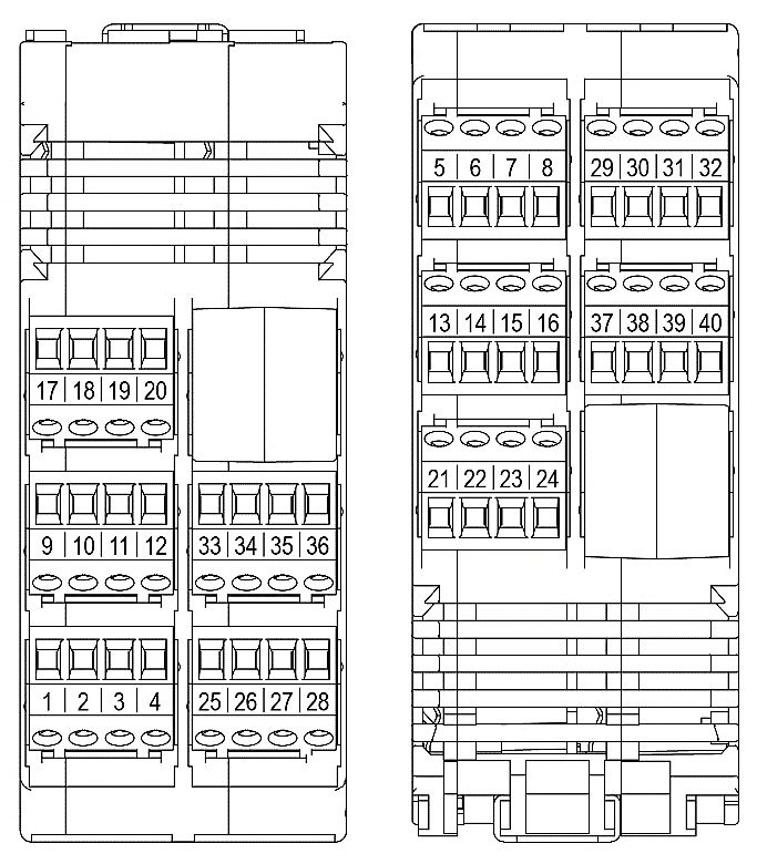
SOMMARIO / TABLE OF CONTENTS
           CONTROLLORE PROGRAMMABILE DI SICUREZZA MZERO ...................................... 3
               IMPORTANTI AVVERTENZE SULLA SICUREZZA ....................................................................................... 3
Italiano

               INTRODUZIONE ............................................................................................................................................. 4
               COLLEGAMENTI ELETTRICI.......................................................................................................................... 4
                  AVVERTENZE SUI CAVI DI COLLEGAMENTO. ..................................................................................................... 5
               MZERO 16.4 PINOUT .................................................................................................................................... 6
               INSTALLAZIONE DEL SOFTWARE ............................................................................................................... 7
                  CARATTERISTICHE HARDWARE RICHIESTE PER IL PC DA COLLEGARE ......................................................... 7
                  CARATTERISTICHE SOFTWARE RICHIESTE PER IL PC DA COLLEGARE .......................................................... 7
                  INSTALLAZIONE DEL SOFTWARE MZD ................................................................................................................ 7
               INGRESSI ......................................................................................................................................................... 7
                  CONNETTORE USB .................................................................................................................................................. 7
                  RESTART_FBK ........................................................................................................................................................... 7
                  INPUT DIGITALI......................................................................................................................................................... 8
               USCITE ............................................................................................................................................................. 8
                  OUT STATUS SIL 1/PL C........................................................................................................................................... 8
                  OUT TEST................................................................................................................................................................... 8
                  OSSD .......................................................................................................................................................................... 8
               CHECKLIST DOPO L'INSTALLAZIONE ........................................................................................................ 9
           CARATTERISTICHE TECNICHE ....................................................................................... 10

           PROGRAMMABLE SAFETY CONTROLLER ................................................................... 11
               IMPORTANT SAFETY INSTRUCTIONS ...................................................................................................... 11
 English

               OVERVIEW .................................................................................................................................................... 12
               ELECTRICAL CONNECTIONS ..................................................................................................................... 12
                  INSTRUCTIONS CONCERNING CONNECTION CABLES. .................................................................................. 13
                  MZERO 16.4 PINOUT ............................................................................................................................................. 14
               INSTALLING THE SOFTWARE .................................................................................................................... 15
                  PC HARDWARE REQUIREMENTS ........................................................................................................................ 15
                  PC SOFTWARE REQUIREMENTS.......................................................................................................................... 15
                  INSTALLATION OF MZD SOFTWARE .................................................................................................................. 15
               INPUTS........................................................................................................................................................... 15
                  USB CONNECTOR .................................................................................................................................................. 15
                  RESTART_FBK ......................................................................................................................................................... 15
                  DIGITAL INPUTS ..................................................................................................................................................... 16
               OUTPUTS ...................................................................................................................................................... 16
                  OUT STATUS SIL 1 PLC ......................................................................................................................................... 16
                  OUT TEST................................................................................................................................................................. 16
                  OSSD ........................................................................................................................................................................ 16
               CHECKLIST AFTER INSTALLATION ........................................................................................................... 17
           TECHNICAL FEATURES .................................................................................................... 18

           DICHIARAZIONE DI CONFORMITÀ / DECLARATION OF CONFORMITY ............... 19

           2                                                                                                                        8541396 • 10/02/2021 • Rev.1
CONTROLLORE PROGRAMMABILE DI SICUREZZA
CONTROLLORE PROGRAMMABILE DI SICUREZZA MZERO
IMPORTANTI AVVERTENZE SULLA SICUREZZA
Questo simbolo indica un avvertimento importante per la sicurezza
delle persone. La sua mancata osservanza può portare ad un rischio
molto elevato per il personale esposto.
Questo simbolo indica un avvertimento importante.
Per un’installazione corretta e sicura è necessario consultare il manuale
istruzioni disponibile nell’area download sul sito web ReeR.
MZERO raggiunge il seguente livello di sicurezza: SIL 3, SILCL 3, PL e,
Cat. 4, Tipo 4 secondo normative applicabili.
Tuttavia il SIL ed il PL finali dell'applicazione dipenderanno dal numero
componenti di sicurezza, dai loro parametri a dai collegamenti
effettuati, come da analisi dei rischi.
Consultare attentamente il paragrafo "Elenco delle Normative
applicabili".
Effettuare una accurata analisi dei rischi per determinare il livello di
sicurezza necessario alla vostra applicazione, facendo riferimento a
tutte le norme applicabili.
La programmazione/configurazione di MZERO viene effettuata
dall'installatore o dall'utilizzatore sotto propria esclusiva responsabilità.
Tale programmazione/configurazione va effettuata in conformità con
l'analisi dei rischi dell'applicazione e con tutte le norme ad essa
applicabili.
Al termine della programmazione/configurazione e dell'installazione di
MZERO e dei dispositivi ad esso collegati, deve essere effettuato un test
esaustivo di sicurezza dell'applicazione to del sistema se aggiunge nuovi
componenti di sicurezza al sistema stesso (consultare il paragrafo "TEST
del sistema", del manuale istruzioni scaricabile dal sito web ReeR).
Il cliente deve operare un controllo completo del sistema se aggiunge
nuovi componenti di sicurezza al sistema stesso (consultare il paragrafo
"TEST del sistema", del manuale scaricabile dal sito ReeR).
ReeR non è responsabile di queste operazioni e di eventuali rischi da
esse derivanti.
Italiano
8541396 • 10/02/2021 • Rev.1 3CONTROLLORE PROGRAMMABILE DI SICUREZZA
Per un corretto utilizzo dei dispositivi collegati a MZERO nell'ambito
della propria applicazione consultarne i manuali ed eventualmente le
relative norme di prodotto e/o di applicazione.
Verificare che la temperatura degli ambienti in cui viene installato il
sistema sia compatibile con i parametri operativi di temperatura indicati
nell'etichetta di prodotto e nei dati tecnici.
Per problemi inerenti la sicurezza, qualora risulti necessario, rivolgersi
alle autorità preposte in materia di sicurezza del proprio paese o alla
associazione industriale competente.
Questa informazione riguarda l'utilizzo e la parametrizzazione di MZERO.
ReeR non si assume alcuna responsabilità per le soluzioni adottate dal
cliente per quanto riguarda i circuiti, i diagrammi elettrici e i parametri
di configurazione scelti.
I circuiti realizzati e gli schemi elettrici e la scelta dei valori dei parametri
di configurazione del sistema, compresi quelli di MZERO, sono da
considerarsi totalmente sotto la responsabilità dell'utente.
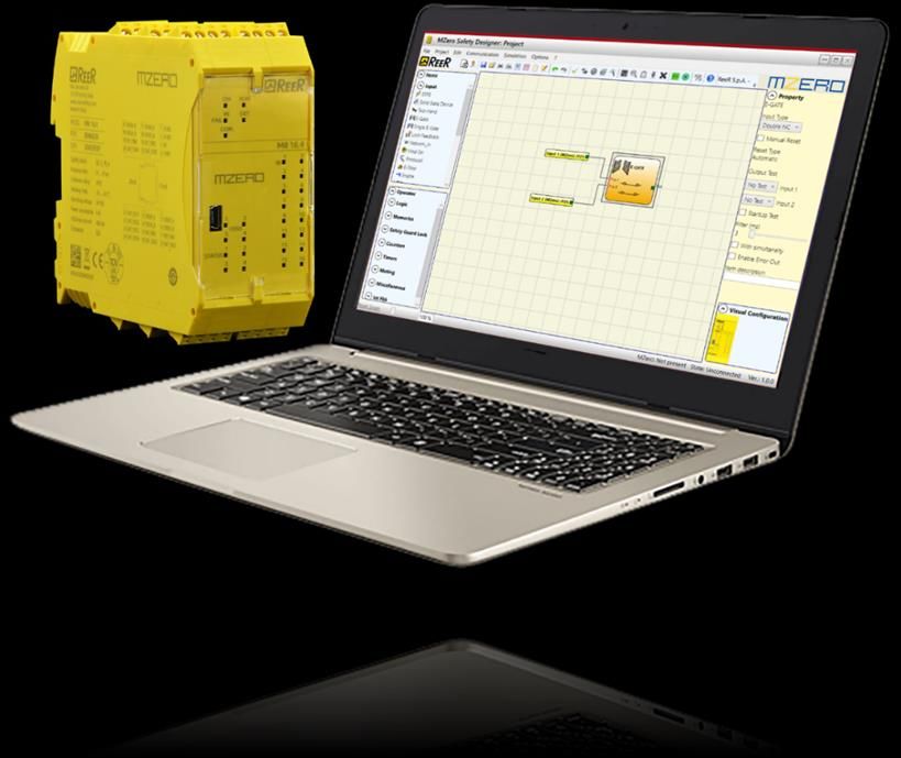
MZD Designer è disponibile nell’area download sul sito web ReeR.
INTRODUZIONE
Questo manuale descrive come installare il Controllore di Sicurezza
Programmabile MZERO che include:
16 Ingressi di sicurezza
4 Ingressi indipendenti programmabili Restart/EDM
4 Uscite di sicurezza a doppio canale (OSSD)
4 SIL 1/PL c - Uscite STATUS
4 Uscite di TEST
COLLEGAMENTI ELETTRICI
Collocare MZERO in un ambiente con grado di protezione almeno IP54.
Collegare il modulo quando non è ancora alimentato.
MZERO deve essere alimentato con tensione di alimentazione
24Vdc 20% (PELV, conforme alla EN 60204-1 (Capitolo 6.4)).
Non utilizzare MZERO come alimentazione per dispositivi esterni.
La connessione di massa (0VDC) deve essere comune a tutti i
Italiano
componenti del sistema.
4 8541396 • 10/02/2021 • Rev.1CONTROLLORE PROGRAMMABILE DI SICUREZZA
AVVERTENZE SUI CAVI DI COLLEGAMENTO.
Dimensione conduttori: AWG 12...30, a filo pieno/a trefolo (UL).
Utilizzare solo conduttori di rame (Cu) 60/75°C.
Si consiglia di tenere separata l'alimentazione di MZERO da quella di
altre apparecchiature elettriche di potenza (motori elettrici, inverter,
variatori di frequenza) o altre fonti di disturbo.
Per collegamenti di lunghezza superiore a 50m occorre utilizzare cavi di
almeno 1mm2 di sezione (AWG16).
Il controllore MZERO è dotato di morsettiere per i collegamenti elettrici.
L’unità dispone di 40 morsetti.
Coppia di serraggio morsettiere: 5÷7lb-in (0,6÷0,7 Nm)
Italiano
Figura 1
8541396 • 10/02/2021 • Rev.1 5CONTROLLORE PROGRAMMABILE DI SICUREZZA
MZERO 16.4 PINOUT
TERMINALE SEGNALE TIPO DESCRIZIONE FUNZIONAMENTO
1 24VDC - Alimentazione 24VDC -
2 24VDC - Alimentazione 24VDC -
3 NC - - -
4 0VDC - Alimentazione 0VDC -
5 OSSD1_A Output PNP attivo alto
Uscita statica 1
6 OSSD1_B Output PNP attivo alto
7 RESTART_FBK1 Input Feedback/Restart 1 Ingresso in accordo a EN 61131-2
8 OUT_STATUS1 Output Uscita SIL 1/PL c PNP attivo alto
9 OSSD2_A Output PNP attivo alto
Uscita statica 2
10 OSSD2_B Output PNP attivo alto
11 RESTART_FBK2 Input Feedback/Restart 2 Ingresso in accordo a EN 61131-2
12 OUT_STATUS2 Output Uscita SIL 1/PL c PNP attivo alto
13 OSSD3_A Output PNP attivo alto
Uscita statica 3
14 OSSD3_B Output PNP attivo alto
15 RESTART_FBK3 Input Feedback/Restart 3 Ingresso in accordo a EN 61131-2
16 OUT_STATUS3 Output Uscita SIL 1/PL c PNP attivo alto
17 OSSD4_A Output PNP attivo alto
Uscita statica 4
18 OSSD4_B Output PNP attivo alto
19 RESTART_FBK4 Input Feedback/Restart 4 Ingresso in accordo a EN 61131-2
20 OUT_STATUS4 Output Uscita SIL 1/PL c PNP attivo alto
21 OUT_TEST1 Output Uscita rilevamento cortocircuiti PNP attivo alto
22 OUT_TEST2 Output Uscita rilevamento cortocircuiti PNP attivo alto
23 OUT_TEST3 Output Uscita rilevamento cortocircuiti PNP attivo alto
24 OUT_TEST4 Output Uscita rilevamento cortocircuiti PNP attivo alto
25 INPUT1 Input Ingresso digitale 1 Ingresso in accordo a EN 61131-2
26 INPUT2 Input Ingresso digitale 2 Ingresso in accordo a EN 61131-2
27 INPUT3 Input Ingresso digitale 3 Ingresso in accordo a EN 61131-2
28 INPUT4 Input Ingresso digitale 4 Ingresso in accordo a EN 61131-2
29 INPUT5 Input Ingresso digitale 5 Ingresso in accordo a EN 61131-2
30 INPUT6 Input Ingresso digitale 6 Ingresso in accordo a EN 61131-2
31 INPUT7 Input Ingresso digitale 7 Ingresso in accordo a EN 61131-2
32 INPUT8 Input Ingresso digitale 8 Ingresso in accordo a EN 61131-2
33 INPUT9 Input Ingresso digitale 9 Ingresso in accordo a EN 61131-2
34 INPUT10 Input Ingresso digitale 10 Ingresso in accordo a EN 61131-2
35 INPUT11 Input Ingresso digitale 11 Ingresso in accordo a EN 61131-2
36 INPUT12 Input Ingresso digitale 12 Ingresso in accordo a EN 61131-2
37 INPUT13 Input Ingresso digitale 13 Ingresso in accordo a EN 61131-2
38 INPUT14 Input Ingresso digitale 14 Ingresso in accordo a EN 61131-2
Italiano
39 INPUT15 Input Ingresso digitale 15 Ingresso in accordo a EN 61131-2
40 INPUT16 Input Ingresso digitale 16 Ingresso in accordo a EN 61131-2
È obbligatorio collegare i pin 1 e 2 all’alimentazione +24VDC.
6 8541396 • 10/02/2021 • Rev.1CONTROLLORE PROGRAMMABILE DI SICUREZZA
INSTALLAZIONE DEL SOFTWARE
CARATTERISTICHE HARDWARE RICHIESTE PER IL PC DA COLLEGARE
• RAM: 2 GB (minimo Windows 7 con Service Pack 1+Framework 4.8)
• Disco rigido: ≥ 500 MB di spazio libero
• Porta USB: 2.0 o superiore
• Collegamento a Internet per il download del programma di installazione
CARATTERISTICHE SOFTWARE RICHIESTE PER IL PC DA COLLEGARE
• Windows 7 con Service Pack 1 (o Sistema Operativo superiore)
• Microsoft Framework 4.8 (o superiore)
INSTALLAZIONE DEL SOFTWARE MZD
• Eseguire il file "SetupDesigner.exe" scaricando l'ultima versione
disponibile dalla sezione Download del sito web di ReeR:
https://www.reersafety.com/download.
• Seguire le indicazioni della procedura di configurazione.
INGRESSI
CONNETTORE USB
MZERO è dotato di un connettore mini USB 2.0 per consentire il
collegamento ad un Personal Computer sul quale risiede il SW di
configurazione MZD (MZERO Safety Designer).
RESTART_FBK
Il segnale RESTART_FBK consente a MZERO di verificare un segnale EDM
(External Device Monitoring) di feedback dei contattori esterni, oltre a
permettere la gestione di funzionamento Manuale/Automatico (vedere le
possibili connessioni nel manuale istruzioni scaricabile dal sito web ReeR).
Ove l'applicazione lo richieda, il tempo di risposta dei contattori esterni
deve essere verificato mediante un dispositivo addizionale.
Il comando di Restart deve essere posizionato al di fuori della zona
pericolosa, in un punto da cui la zona pericolosa e l'intera area di lavoro
interessata risultino ben visibili.
Italiano
Non deve essere possibile raggiungere il comando dall'interno dell'area
pericolosa.
8541396 • 10/02/2021 • Rev.1 7CONTROLLORE PROGRAMMABILE DI SICUREZZA
INPUT DIGITALI
MZERO fornisce 16 ingressi digitali PNP attivo alto che permettono il
collegamento con i componenti hardware del progetto.
Questi ingressi sono progettati secondo la norma EN 61131-2 Tipo 3.
USCITE
OUT STATUS SIL 1/PL C
Il segnale OUT STATUS (SIL 1/PL c) è un'uscita digitale programmabile che
può riportare lo stato di:
Un'ingresso.
Un'uscita.
Un nodo dello schema logico progettato con MZD.
OUT TEST
I segnali OUT TEST devono essere utilizzati per monitorare la presenza di
corto circuiti o sovraccarichi sugli ingressi.
Il numero massimo di ingressi controllabili per ogni uscita OUT TEST è 4
(collegamento in parallelo).
La lunghezza massima consentita per i collegamenti del segnale OUT
TEST è = 100m.
OSSD
Le uscite OSSD (statiche di sicurezza a semiconduttore) sono protette
contro i cortocircuiti e hanno le seguente caratteristiche:
In stato di ON: Uv-1,2V...Uv (con Uv pari a 24V ± 20%)
In stato di OFF: 0V...2V r.m.s.
Il massimo carico è 400mA@24VDC, corrispondente a un minimo
carico resistivo di 60.
Il massimo carico capacitivo è pari a 0.68 F. Il massimo carico
induttivo è pari a 2 mH.
Italiano
8 8541396 • 10/02/2021 • Rev.1CONTROLLORE PROGRAMMABILE DI SICUREZZA
CHECKLIST DOPO L'INSTALLAZIONE
MZERO è in grado di rilevare in tempo reale i guasti.
Tuttavia al fine di garantire il corretto funzionamento del sistema,
effettuare i seguenti controlli dopo l’installazione e almeno una volta
all'anno:
OPERAZIONE / CONTROLLO COMPLETATO
1. Effettuare un TEST completo del sistema
(consultare il paragrafo "TEST del sistema", del manuale ❒
istruzioni scaricabile dal sito web ReeR)
2. Verificare che i conduttori siano correttamente avvitati alle
❒
morsettiere
3. Verificare che tutti i led (indicatori) si accendano
❒
correttamente
4. Verificare il corretto posizionamento di tutti i sensori collegati
❒
a MZERO
5. Verificare il corretto fissaggio di MZERO alla barra Omega ❒
6. Verificare che tutti gli indicatori esterni funzionino
❒
correttamente
Italiano
8541396 • 10/02/2021 • Rev.1 9CONTROLLORE PROGRAMMABILE DI SICUREZZA
CARATTERISTICHE TECNICHE
PARAMETRO VALORE NORMATIVA
PFHd 1,50E-8
SIL 3 EN 61508:2010
SFF 99,7%
SILCL 3 EN 62061:2005 / A2:2015
Tipo 4 EN 61496-1:2020
PL E
Dcavg 98,9% EN ISO 13849-1:2015
MTTFd 160,81 anni EN 62061:2005 / A2:2015
Tempo di vita del dispositivo 20 anni
PARAMETRO VALORE
24 VDC + 20% / PELV, Classe di protezione III;
Tensione nominale
UL: Alimentazione di classe 2 (LVLE)
Potenza dissipata 6W max
Tempo di risposta (ms) 22…24 (max)
INPUT digitali (No./descrizione) 16 / PNP attivo alto, secondo EN 61131-2 (tipo 3)
4 / controllo feedback contattori esterni; possibile
INPUT FBK/RESTART
funzionamento Automatico o Manuale con pulsante di
(No./descrizione)
RESTART secondo EN 61131-2 (tipo 2)
Test OUTPUT (No./descrizione) 4 / per controllo corto circuiti - sovraccarichi
SIL 1/PL c OUTPUTS
4 / programmabili - PNP attivo alto
(No./descrizione)
4 coppie / Uscite statiche di sicurezza PNP attivo alto
OSSD (No./descrizione) 400mA@24 VDC max. Interfaccia tipo C classe 3 (ZVEI
CB24I)
Connessione al PC USB 2.0 (Hi Speed) - Max lunghezza cavo: 3m
PARAMETRO VALORE
Custodia per elettronica 40 poli, con gancio metallico di
Descrizione
arresto
Materiale contenitore Poliammide
Grado di protezione contenitore IP 20
Grado di protezione morsettiera IP 2X
Fissaggio Attacco rapido su barra secondo la norma CEI EN 60715
Dimensioni (h x l x p) 108 x 45 x 114.5
La precisa ed integrale osservanza di tutte le norme, indicazioni e divieti esposti
nel manuale del modulo MZERO, scaricabile dal sito web ReeR, costituisce un
requisito essenziale per il corretto funzionamento del modulo MZERO.
ReeR s.p.a., pertanto, declina ogni responsabilità per quanto derivante dal
mancato rispetto, anche parziale, di tali indicazioni.
Italiano
Il software MZD e la manualistica sono reperibili all’URL: https://www.reersafety.com/download
10 8541396 • 10/02/2021 • Rev.1PROGRAMMABLE SAFETY CONTROLLER
PROGRAMMABLE SAFETY CONTROLLER
IMPORTANT SAFETY INSTRUCTIONS
This safety alert symbol indicates a potential personal safety hazard.
Failure to comply with instructions bearing this symbol could pose a very
serious risk to personnel.
This symbol indicates an important instruction.
To guarantee a correct and safe installation and operation of the
module, it is necessary to consult the instruction manual available in
download area on the ReeR website.
MZERO is built to the following safety levels: SIL 3, SILCL 3, PL e, Cat. 4,
Type 4 in accordance with the applicable standards. However, the
definitive SIL and PL of the application will depend on the number of
safety components, their parameters and the connections that are
made, as per the risk analysis.
Read the "Applicable Standards" section carefully.
Perform an in-depth risk analysis to determine the appropriate safety
level for your specific application, on the basis of all the applicable
standards.
Programming/configuration of the MZERO is the sole responsibility of
the installer or user.
The device must be programmed/configured in accordance with the
application-specific risk analysis and all the applicable standards.
Once you have programmed/configured and installed the MZERO and
all the relative devices, run a complete application safety test (see
"TESTING the system", in the instruction manual available on the ReeR
website).
Always test the complete system whenever new safety components are
added (see "TESTING the system", in the instruction manual available on
the ReeR website).
ReeR is not responsible for these operations or any risks in connection
therewith.
Reference should be made to the handbooks and the relative product
and/or application standards to ensure correct use of devices connected
English
to the MZERO within the specific application.
8541396 • 10/02/2021 • Rev.1 11PROGRAMMABLE SAFETY CONTROLLER
The ambient temperature in the place where the system is installed
must be compatible with the operating temperature parameters stated
on the product label and in the specifications.
For all matters concerning safety, if necessary, contact your country's
competent safety authorities or the competent trade association.
This information is about the usage and parametrisation of MZERO.
ReeR takes no responsibility for the solutions adopted by customers
concerning the circuits, the electrical diagrams and the chosen
configuration parameters of their application.
The implemented circuits and electrical diagrams and the choice of the
system configuration parameter values, including those of MZERO, are
fully under the responsibility of the user.
MZD Designer available in download area on the ReeR website.
OVERVIEW
This handbook describes how to install the MZERO Stand Alone
Programmable Safety Controller; it includes:
16 Safety Inputs
4 independent programmable Restart/EDM Inputs
4 independent safety dual channel Outputs (OSSD)
4 SIL 1/PL c - Status outputs
4 Test Outputs
ELECTRICAL CONNECTIONS
Install the safety controller in an enclosure with a protection class of at
least IP54.
Connect the module when it is not powered.
The supply voltage to MZERO must be 24Vdc 20% (PELV, in compliance
with the standard EN 60204-1 (Chapter 6.4)).
Do not use the MZERO to supply external devices.
The same ground connection (0VDC) must be used for all system
components.
English
12 8541396 • 10/02/2021 • Rev.1PROGRAMMABLE SAFETY CONTROLLER
INSTRUCTIONS CONCERNING CONNECTION CABLES.
Wire size range: AWG 12...30, (solid/stranded) (UL).
Use 60/75°C copper (Cu) conductor only.
We recommend the use of separate power supplies for the safety
module and for other electrical power equipment (electric motors,
inverters, frequency converters) or other sources of disturbance.
Cables used for connections of longer than 50m must have a cross-
section of at least 1mm2 (AWG16).
The MZERO controller is provided with terminal blocks for the electrical
connections.
The unit provides 40 terminals.
Terminal tightening torque: 5...7lb-in (0,6...0,7 Nm).
English
Figure 2
8541396 • 10/02/2021 • Rev.1 13PROGRAMMABLE SAFETY CONTROLLER
MZERO 16.4 PINOUT
TERMINAL SIGNAL TYPE DESCRIPTION OPERATION
1 24VDC - 24VDC power supply -
2 24VDC - 24VDC power supply -
3 NC - - -
4 0VDC - 0VDC power supply -
5 OSSD1_A Output PNP active high
Static output 1
6 OSSD1_B Output PNP active high
7 RESTART_FBK1 Input Feedback/Restart 1 Input (type 2) according to EN 61131-2
8 OUT_STATUS1 Output SIL 1/PL c output PNP active high
9 OSSD2_A Output PNP active high
Static output 2
10 OSSD2_B Output PNP active high
11 RESTART_FBK2 Input Feedback/Restart 2 Input (type 2) according to EN 61131-2
12 OUT_STATUS2 Output SIL 1/PL c output PNP active high
13 OSSD3_A Output PNP active high
Static output 3
14 OSSD3_B Output PNP active high
15 RESTART_FBK3 Input Feedback/Restart 3 Input (type 2) according to EN 61131-2
16 OUT_STATUS3 Output SIL 1/PL c output PNP active high
17 OSSD4_A Output PNP active high
Static output 4
18 OSSD4_B Output PNP active high
19 RESTART_FBK4 Input Feedback/Restart 4 Input (type 2) according to EN 61131-2
20 OUT_STATUS4 Output SIL 1/PL c output PNP active high
21 OUT_TEST1 Output Short circuit detection output PNP active high
22 OUT_TEST2 Output Short circuit detection output PNP active high
23 OUT_TEST3 Output Short circuit detection output PNP active high
24 OUT_TEST4 Output Short circuit detection output PNP active high
25 INPUT1 Input Digital input 1 Input (type 3) according to EN 61131-2
26 INPUT2 Input Digital input 2 Input (type 3) according to EN 61131-2
27 INPUT3 Input Digital input 3 Input (type 3) according to EN 61131-2
28 INPUT4 Input Digital input 4 Input (type 3) according to EN 61131-2
29 INPUT5 Input Digital input 5 Input (type 3) according to EN 61131-2
30 INPUT6 Input Digital input 6 Input (type 3) according to EN 61131-2
31 INPUT7 Input Digital input 7 Input (type 3) according to EN 61131-2
32 INPUT8 Input Digital input 8 Input (type 3) according to EN 61131-2
33 INPUT9 Input Digital input 9 Input (type 3) according to EN 61131-2
34 INPUT10 Input Digital input 10 Input (type 3) according to EN 61131-2
35 INPUT11 Input Digital input 11 Input (type 3) according to EN 61131-2
36 INPUT12 Input Digital input 12 Input (type 3) according to EN 61131-2
37 INPUT13 Input Digital input 13 Input (type 3) according to EN 61131-2
38 INPUT14 Input Digital input 14 Input (type 3) according to EN 61131-2
39 INPUT15 Input Digital input 15 Input (type 3) according to EN 61131-2
English
40 INPUT16 Input Digital input 16 Input (type 3) according to EN 61131-2
It is mandatory to connect pins 1 and 2 to +24VDC power supply.
14 8541396 • 10/02/2021 • Rev.1PROGRAMMABLE SAFETY CONTROLLER
INSTALLING THE SOFTWARE
PC HARDWARE REQUIREMENTS
• RAM: 2 GB (minimum to run 7 with Service Pack 1 + Framework 4.8)
• Hard disk: ≥ 500 MB free space
• USB port: 2.0 or greater
• Internet connection for installation program download
PC SOFTWARE REQUIREMENTS
• Windows 7 with Service Pack 1 installed (or higher OS)
• Microsoft Framework 4.8 (or higher)
INSTALLATION OF MZD SOFTWARE
• Run the “SetupDesigner.exe” file downloading the last available version
from the download section of the ReeR website:
https://www.reersafety.com/download.
• Follow the indications of the setup procedure.
INPUTS
USB CONNECTOR
MZERO comes with a mini USB 2.0 connector for the connection to a PC
that is hosting the configuration software (MZD Safety MZERO Designer).
RESTART_FBK
The RESTART_FBK signal input allows the MZERO to verify an EDM
(External Device Monitoring) feedback signal (series of contacts) from the
external contactors, and to monitor Manual/Automatic operation (see all
possible connections in the instruction manual available on ReeR website).
If the application requires it, the response time of the external
contactors must be verified by an additional device.
The RESTART command must be installed outside the danger area in a
position where the danger area and the entire work area concerned are
clearly visible.
English
It must not be possible to reach the control from inside the danger area.
8541396 • 10/02/2021 • Rev.1 15PROGRAMMABLE SAFETY CONTROLLER
DIGITAL INPUTS
MZERO provides 16 high active PNP digital inputs that allow connection to
the project's hardware components.
This inputs are designed according to EN 61131-2 Type 3 standard.
OUTPUTS
OUT STATUS SIL 1 PLC
The OUT STATUS signal is a programmable digital output that can indicate
the status of:
An input.
An output.
A node of the logic diagram designed using the MZD.
OUT TEST
The OUT TEST signals must be used to monitor the presence of short-
circuits or overloads on the inputs.
The maximum number of controllable inputs for each OUT TEST output
is 4 (parallel connection).
The maximum permissible length for OUT TEST signal connections is =
100m.
OSSD
The OSSD (static semiconductor safety outputs) are short circuit protected.
They supply:
In the ON condition: Uv-1,2V...Uv (where Uv is 24V ± 20%)
In the OFF condition: 0V...2V r.m.s.
The maximum load of 400mA@24V corresponds to a minimum resistive
load of 60.
The maximum capacitive load is 0.68F. The maximum inductive load is
English
2mH.
16 8541396 • 10/02/2021 • Rev.1PROGRAMMABLE SAFETY CONTROLLER
CHECKLIST AFTER INSTALLATION
The MZERO controller is able to detect in real time the faults.
Anyway to guarantee a system perfect operation perform the following
checks at start up and at least every one year:
OPERATION / CONTROL COMPLETE
1. Operate a complete system TEST
(see "TESTING the system", in the instruction manual available on ❒
the ReeR website)
2. Verify that all the cables are correctly inserted and the terminal
❒
blocks well screwed
3. Verify that all the leds (indicators) light on correctly ❒
4. Verify the positioning of all the sensors connected to MZERO ❒
5. Verify the correct fixing of MZERO to the Omega rail ❒
6. Verify that all the external indicators (lamps) work properly ❒
English
8541396 • 10/02/2021 • Rev.1 17PROGRAMMABLE SAFETY CONTROLLER
TECHNICAL FEATURES
PARAMETER VALUE STANDARD
PFHd 1,50E-8
SIL 3 EN 61508:2010
SFF 99,7%
SILCL 3 EN 62061:2005 / A2:2015
Type 4 EN 61496-1:2020
PL E
Dcavg 98,9% EN ISO 13849-1:2015
MTTFd 160,81 years EN 62061:2005 / A2:2015
Device lifetime 20 years
PARAMETER VALUE
24VDC + 20% / PELV, Protective Class III; UL: Supply from class 2
Rated voltage
(LVLE)
Dissipated power 6W max
Response time (ms) 22…24 (max)
INPUT digitali
16 / PNP active high according to EN 61131-2 (type 3)
(No./descrizione)
4 / external contactors feedback control; possible Automatic or
INPUT FBK/RESTART
Manual operation with RESTART button, PNP active high
(No./description)
according to EN 61131-2 (type 2)
Test OUTPUT
4 / to check for short-circuits - overloads
(No./description)
SIL 1/PL c OUTPUTS
4 / programmable - PNP active high
(No./ description)
4 pairs / solid state safety outputs PNP active high
OSSD (No./descrizione)
400mA@24VDC max; Interface type C class 3 (ZVEI CB24I)
Connection to PC USB 2.0 (Hi Speed) - Max cable length: 3m
PARAMETER VALUE
Description Electronic housing 40 pole, with locking latch mounting
Enclosure material Polyamide
Enclosure protection class IP 20
Terminal blocks
IP 2X
protection class
Fastening Quick coupling to rail according to CEI EN 60715
Dimensions (h x l x d) 108 x 45 x 114.5
Precise, complete compliance with all standards, instructions and warnings in
MZERO handbook is essential for the correct operation of MZERO controller.
ReeR therefore declines any responsibility for all and anything resulting from
English
failure to comply with all or some of the aforesaid instructions.
The MZD software and manual are available at URL: https://www.reersafety.com/download
18 8541396 • 10/02/2021 • Rev.1DICHIARAZIONE DI CONFORMITÀ / DECLARATION OF CONFORMITY Fare riferimento al manuale istruzioni per la Dichiarazione di Conformità CE completa. Refer to the instruction manual for the complete EC Declaration of Conformity. 8541396 • 10/02/2021 • Rev.1 19
All REER product manuals are available at URL
     https://www.reersafety.com/it/en/download/manuals

20                                           8541396 • 10/02/2021 • Rev.1
Puoi anche leggere