GRIM EU PONTI SU RUOTE A TORRE - Marchetti Scale
←
→
Trascrizione del contenuto della pagina
Se il tuo browser non visualizza correttamente la pagina, ti preghiamo di leggere il contenuto della pagina quaggiù
Norma Europea EN 1004                          Istruzioni per l’uso
                                                                    e la manutenzione

              www.marchetti.eu

PONTI SU RUOTE A TORRE
GRIM EU
I prodotti identificati in questo manuale sono
stati realizzati da MARCHETTI s.r.l. con SISTEMA
DI GESTIONE QUALITÀ certificato da TÜV Italia, in
accordo alla norma ISO 9001.

                                                                          DOC. ASSISTENZA CLIENTE
                                                                       N. 146 REV. 0 DEL 27/08/2020
                                                                                         Code 11301
Manuale d’istruzioni EN 1298 – IM – it x en
I ponti su ruote a torre devono essere utilizzati solo per lavori di finitura, manutenzione o simili.
Il presente Manuale d’Istruzioni contiene importanti indicazioni riguardanti l’uso, la manutenzione
e la sicurezza dei ponti su ruote a torre; l’operatore ne deve avere completa conoscenza prima
dell’utilizzo. Osservando scrupolosamente il presente Manuale, significa operare in conformità a
quanto disposto dall’attuale normativa sulla salute e sicurezza sul lavoro D.Lgs. 09.04.2008 n° 81.

MARCHETTI S.r.l.
Via Piemonte, 22                                                          info@marchetti.eu
06062 Città della Pieve - Perugia - Italy                                 www.marchetti.eu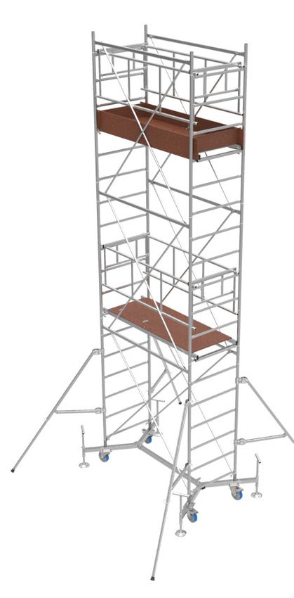
www.marchetti.eu

        ATTENZIONE:
        •      leggere e comprendere questo manuale in ogni sua
               parte.
        •      attenersi scrupolosamente a quanto indicato.
        •      prima di ogni montaggio verificare l’integrità di ogni
               singolo componente.
        •      Non utilizzare tutti quei componenti che risultino
               danneggiati o non integri.
        •      Il ponteggio è costruito secondo le norme di riferimento.
               Qualunque modifica fatta da terzi fa decadere la
               responsabilità del costruttore

        GARANZIA
        Tutti i prodotti MARCHETTI hanno la garanzia ufficiale della casa in ottemperanza alla
        normativa vigente. È garantito il prodotto solo contro i difetti di fabbricazione. Non si
        addebitano alla nostra responsabilità prodotti mal usati o carenti di manutenzione,
        danneggiati per il trasporto, con componenti diversi dagli originali o trasformati da
        terzi,per parti soggette ad uso di utilizzo.

        DIRITTI D’AUTORE
        La presente documentazione è tutelata dal diritto d’autore. Qualsiasi riproduzione o
        ristampa, anche parziale, ovvero la riproduzione delle immagini, anche se modificate, è
        consentita solo previo permesso scritto del produttore.

                                                     2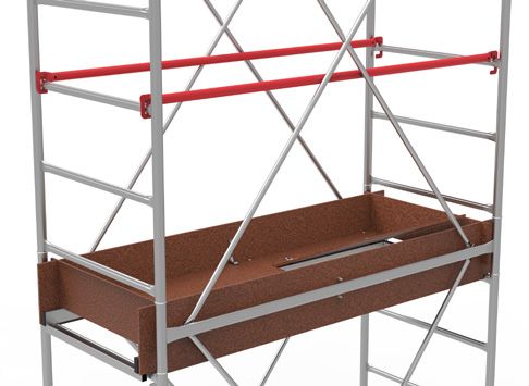
IT
RIFERIMENTI NORMATIVI
- D.Lgs. 09.04.2008 n° 81 (G.U. n° 101 del 30.04.08) “Testo unico sulla salute e sicurezza sul lavoro”.
- EN 1004 (luglio 2005) “Torri mobili di accesso e di lavoro (ponti su ruote a torre) costituite da
  elementi prefabbricati. Materiali, dimensioni, carichi di progetto, requisiti di sicurezza e
  prestazionali”;
- EN 1298 (febbraio 1996) “Torri mobili da lavoro. Regole e linee guida per la preparazione di un
  Manuale d’istruzioni”;
- D.Lgs. 06.09.2005 n° 206 (G.U. n° 235 del 08.10.05 – Suppl. Ordinario n° 162) “Codice del Consumo”.

DESIGNAZIONE - CLASSE - PORTATA
GRIM EU75 su base estraibile, torre di lavoro EN 1004 – 3 – 6 / 6 XXCD.
GRIM EU75 su base normale, torre di lavoro EN 1004 – 3 – 4,40 / 4,40 XXCD.
Costruito in conformità al D.Lgs. 81/08 e Norma Tecnica EN 1004;
Classe dei carichi distribuiti in modo uniforme pari a “3” (2,0 KN/m2);
- Altezza massima consentita del piano di lavoro pari a m 5,00 sia all’esterno che all’interno di
  edifici. Per interno si intende assenza di vento
- Il carico complessivo consentito per ogni torre risulta pertanto di kg 190.
- Il numero massimo di piani caricati contemporaneamente è di n° 2.
- La somma dei carichi relativi ad ogni piano non deve superare il valore del carico complessivo

                          DICHIARAZIONE DI CONFORMITÀ
             MARCHETTI s.r.l. con sede in Città della Pieve (PG) via Piemonte 22
                                            DICHIARA:
•   che il ponte su ruote a torre denominato GRIM EU75 viene costruito in conformità al D.Lgs.
    09.04.2008 n° 81 ed in particolare alla Norma Tecnica EN 1004 (luglio 2005)
•   che lo stesso viene costruito in modo conforme al prototipo che ha superato la prova di
    rigidità, di cui all’appendice “A” della Norma Tecnica EN 1004 (2005) e che è stato sottoposto,
    con esito positivo, alla VALUTAZIONE così come previsto al p.to 13 della Norma Tecnica EN
    1004 (2005) presso:
         UNIVERSITA’ DEGLI STUDI DI PERUGIA - Dipartimento di Ingegneria Industriale -
                                        Certificato n° Marc 85
•   che su tutti gli esemplari prodotti è riportata la marcatura di identificazione ed un Manuale
    d’Istruzioni redatto secondo quanto prescritto dalla Norma Tecnica EN1298 (p.to 9 della Norma
    Tecnica EN 1004).
                                                                                        Marchetti s.r.l.

                                                   3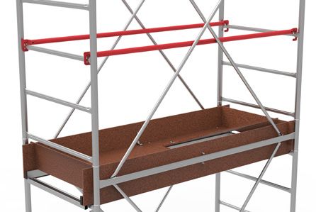
www.marchetti.eu

 INFORMAZIONI GENERALI
 Accesso ai piani di lavoro

 L’accesso ai piani di lavoro può avvenire solamente dall’interno della torre utilizzando uno
 dei seguenti metodi:

 - scala a pioli verticale, costituita dai traversi dei telai laterali della struttura

 - scala a pioli inclinata, interna

 - scala a gradini inclinata, interna

 Altezze massime nelle configurazioni EN 1004

 Base normale: altezza massima m 1,80 senza staffe / m 4,40 con staffe

 Base estraibile: altezza massima m 2,70 senza staffe / m 6,00 con staffe

 Le staffe stabilizzatrici sono di due tipi: Normali-30 e Super-30.

 Le staffe Normali devono essere montate all’interno.

 All’esterno devono essere montate per altezze del piano di lavoro inferiori a m 5,00 quando
 la torre è completamente esposta al vento.

 Quando i ponti a torre su ruote sono montati accanto ad una parete (es. facciata di edifici)
 tale da costituire barriera al vento possono essere montate le staffe Normali in alternativa
 delle Super. In quest’ultimo caso le staffe lato parete dovranno essere orientate verso l’ester-
 no della torre in posizione parallela alla parete.

 Le staffe Super-30 devono essere montate sui ponti quando il piano di lavoro supera la quota
 di m 5,00 e il ponte è completamente esposto al vento (es. in mezzo ad un piazzale, accanto
 ad una struttura tipo palo della luce, che non costituisce barriera al vento, ecc.).

 Altezza libera minima tra i piani di lavoro: m 1,90.

 Distanza massima verticale tra i piani di lavoro; m 4,20.

 Distanza massima verticale tra il pavimento ed il primo piano: m 4,60.

                                                   4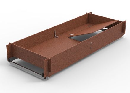
IT
IDENTIFICAZIONE
EN 1004 Classe “3” (2,00 KN/mq)

Carico complessivo consentito Kg 190

Numero massimo di piani caricati contemporaneamente 2

                Tabella degli elementi componenti nelle configurazioni
                                                 Peso              CONFIGURAZIONI
     Cod.         Elementi Componenti
                                                  Kg     A1   A2   A3   B1    B2    B3    B4
     20596 BASE ESTRAIBILE
 1 20573 Blocco porta-ruote base estraibile      9,00    0    0    0     2    2     2     2
 2 20574 Corrente base estraibile                3,30    0    0    0     1    1     1     1
 3 20318 Piedino regolabile estraibile           3,50    0    0    0     4    4     4     4
 4 30522 Vite con impugnatura M12X80             0,14    0    0    0     2    2     2     2
     20641 BASE NORMALE
 5 20642 Blocco porta-ruote base normale         4,50    2    2    2     0    0     0     0
 6 20644 Diagonale - 160                         0,90    1    1    1     0    0     0     0
     20595 TORRE
 7 20568 Telaio portante                         7,60    2    4    6     2    4     6     8
 8 20570 Corrente di collegamento                2,10    2    4    6     2    4     6     8
 9 20571 Asta controventamento                   1,20    4    8    12    4    8     12    16
     21082 PIANO LAVORO ACCIAIO
20          Piano con botola - 165               17,05   1    1    1     1    1     1     2
21 21082 Tavola fermap.Lunga - 165               3,26    2    2    2     2    2     2     4
22          Tavola fermap. Corta - 75            1,03    2    2    2     2    2     2     4
     20752 PARAPETTO COMPLETO
15 20643 Parapetto lungo - 165                   4,90    2    2    2     2    2     2     2
16 20786 Parapetto corto - 75                    1,70    2    2    2     2    2     2     2
            ASTA PARAPETTO
23 20112 Asta parapetto Grimeu 75                1,76    0    0    0     0    0     0     2
     20713 STAFFE STABILIZZATRICI
17 20766 Staffa stabilizzatrice - 30             5,40    0    4    4     0    0     4     4
18 31619 Giunto staffe - 30                      0,50    0    8    8     0    0     8     8
     21559 STAFFE STABILIZZATRICI
17 21559 Staffa stabilizzatrice telescopica-30   5,40    0    4    4     0    0     4     4

                                                  5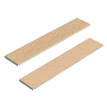
www.marchetti.eu

  Per realizzare le configurazioni con l’alzata terminale da H=0,85 m ( A1T - A2T - B1T
  - B2T - B3T) è sufficiente aggiungere i seguenti elementi componenti:
                                                                     Peso                   CONFIGURAZIONI
             Cod.                 Elementi Componenti
                                                                      Kg         A1T       A2T   B1T    B2T   B3T
             20597 BASE ESTRAIBILE
   10        20569 Telaio portante terminale                         3,50         2         2     2      2     2
    8        20570 Corrente collegamento                             2,10         2         2     2      2     2
   11        20572 Asta controventamento terminale 0,90                           4         4     4      4     4

 ELEMENTI COMPONENTI

                                  4

              2
  Base Estraibile
  EN 1004                   3             1
  con freno e 4 ruote Ø 150
                                                          16
                                                                            15

                         5
             6

   Base Normale                                        Parapetto
   EN 1004
   con freno e 4 ruote Ø 150
                                                  23
        22          21
                             20

                                                         Aste parapetto
                                                                                      18

 Piano di lavoro
                              8                                                       17

                                                  8
                                      7

                                                                             10
                                                               11
         9

 Alzata H=1,70 m                              Alzata terminale H=0,85m

                                                                     6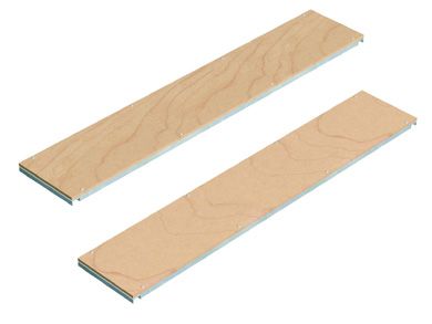
IT
CONFIGURAZIONI POSSIBILI SECONDO EN 1004

                    CONFIGURAZIONI AMMESSE SU BASE NORMALE         CONFIGURAZIONI AMMESSE SU BASE ESTRAIBILE

                    CONFIGURAZIONI POSSIBILI SECONDO EN 1004 SIA ALL’INTERNO CHE ALL’ESTERNO DI EDIFICI

 BASE NORMALE
 CONFIGURAZIONE                                       A1            A1T            A2           A2T            A3
 Altezza max ponteggio                     m         2,00           2,85          3,70          4,55       5,40
 Altezza max piano lavoro                  m         1,00           1,85          2,70          3,55       4,40
 Alzata torre ( H= 1,70 m)                 n°          1              1             2             2            3
 Alzata torre ( H= 0,85 m)                 n°          0              1             0             1            0
 Piani di lavoro                           n°          1              1             1             1            1
 Parapetto completo                        n°          1              1             1             1            1
 Asta parapetto                            n°          0              0             0             0            0
 Staffe stabilizzatrici-30                 n°          0              0             4             4            4
 Sezione di base Normale                   n°          1              1             1             1            1

 BASE ESTRAIBILE
 CONFIGURAZIONE                                       B1            B1T            B2           B2T            B3   B3T    B4
 Altezza max ponteggio                     m         2,00          2,85           3,70          4,55       5,40     6,25   7,10
 Altezza max piano lavoro                  m         1,00          1,85           2,70          3,55       4,40     5,25   6,00
 Alzata torre ( H= 1,70 m)                 n°          1              1             2             2            3     3      4
 Alzata torre ( H= 0,85 m)                 n°          0              1             0             1            0     1      0
 Piani di lavoro                           n°          1              1             1             1            1     2      2
 Parapetto completo                        n°          1              1             1             1            1     1      1
 Asta parapetto                            n°          0              0             0             0            0     2      2
 Staffe stabilizzatrici-30                n°           0              0             0             4            4     4      4
 Sezione di base Estraibile               n°           1              1             1             1            1     1      1

                                                                      7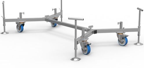
www.marchetti.eu

           Informazioni generali
 •      Per il montaggio e lo smontaggio dei ponti su ruote a torre sono necessarie almeno 2 persone ed
        è indispensabile che abbiano dimestichezza con le istruzioni di montaggio e uso;
 •      non devono essere usati componenti danneggiati;
 •      devono essere impiegati solo componenti originali secondo quanto indicato dal costruttore.
 PARAPETTO COMPLETO EN 1004
 La protezione laterale è costituita da 2 telai in tubi di acciaio uniti da 2 elementi, tali da garantire sia la
 protezione superiore che quella intermedia. Vengono agganciati ai traversi laterali in modo da impe-
 dire il distacco accidentale. Da utilizzare come parapetto finale di lavoro.
 ASTA PARAPETTO
 Aste in acciaio con dispositivo antisfilo alle estremità. Da utilizzare come protezione nei piani di
 passaggio. Qualora tali piani fossero usati come sosta o di lavoro è obbligatorio l’uso del parapetto
 EN 1004.

 SOTTOPONTE (D.Lgs. 09.04.2008 n° 81 Sez. IV - art. 128)
 Il sottoponte (piano di lavoro di sicurezza, costruito come il piano normale) è obbligatorio per lavori
 di manutenzione e riparazione se di durata superiore a 5 gg. e sempre obbligatorio per i lavori di
 costruzione, deve essere posizionato sotto al piano di lavoro ad una distanza non superiore a m 2,50.

           VERIFICHE PRELIMINARI
 •       La superficie sulla quale viene montato il ponte e successivamente spostato (se necessario)
         deve essere in grado di reggerne il peso, deve essere perfettamente livellata e tale da garantire
         la ripartizione del carico, magari facendo uso di tavoloni o altri mezzi equivalenti;
 •       deve essere assicurata l’assenza di qualunque tipo di ostacolo;
 •       le operazioni di montaggio possono iniziare solo in assenza di vento;
 •       deve essere verificato che tutti gli elementi, gli utensili accessori e le attrezzature di sicurezza
         per il montaggio del ponteggio a torre siano disponibili in loco;
 •       La verticalità dei ponti su ruote deve essere controllata con livella in dotazione.

 MONTAGGIO E SMONTAGGIO GRIM EU75 BASE ESTRAIBILE
 •       collegare i 2 blocchi porta-ruote con i 1 correnti di base mediante le 2 viti con impugnatura, in
         dotazione;
 •       prima di serrare completamente le viti montare i primi 2 telai laterali;
 •       serrate le viti, inserire i freni nelle 4 ruote ed estrarre i piedini regolabili, della massima quantità
         compatibile con gli ingombri circostanti. Sfilare gli estraibili fino la linea con la scritta MAX
 •       livellare la base agendo sulla vite dei piedini, sollevando da terra tutte le ruote almeno di mm 20,
         a livellamento avvenuto, serrare i controdadi;
 •       proseguire le operazioni di montaggio innestando i correnti di collegamento, avendo cura di
         posizionare i nottolini verso l’interno e le etichette verso l’esterno.
 •       porre in opera le aste di controventamento, agganciando le estremità ai nottolini anti-sfilo dei
         correnti;
                                                         8
IT
• Posizionare gli elementi piani dell’impalcato sul quarto piolo dal basso dei primi due telai laterali;
• posizionare prima le 2 tavole fermapiede lunghe parallelamente al piano di calpestio, inserire le 2
tavole fermapiede corte, alloggiandole nelle rispettive sedi presenti nelle tavole lunghe.
• a questo punto, almeno uno degli operatori addetti al montaggio dovrà indossare una cintura di
sicurezza e salire sul piano di lavoro dall’interno della torre, attraverso l’apposita botola;
• Proseguire il montaggio dell’alzata superiore con l’inserimento delle estremità dei correnti e
delle aste di controventamento ai perni presenti sui telai.
• dopo aver assicurato l’estremità della fune della cintura di sicurezza ad uno dei due correnti di
collegamento già fissati, inserire i successivi n° 2 telai laterali e continuare il montaggio seguendo
la stessa sequenza delle operazioni fin qui descritta;
• ad un’ altezza maggiore di m 1,80, del piano di lavoro, è necessario montare le n° 4 staffe stabiliz-
zatrici.
• predisporre le staffe stabilizzatrici in posizione aperta. Fasciare con il giunto il montante della
torre e la staffa stabilizzatrice, nella sua parte più alta, in corrispondenza di un traverso del te-
laio, formando un angolo di 120° ca. rispetto al lato lungo del ponte e avvitare il dado-golfare.
Ripetere l’operazione con un secondo giunto, nello stesso montante, in corrispondenza del traver-
so sotto al primo, per accogliere la stessa staffa. Ripetere le operazioni con la stessa sequenza per
gli altri tre montanti della torre.
• man mano che procedono le operazioni di montaggio della torre, collocare gli impalcati in po-
sizione tale, da garantire all’operatore in quota, movimenti agili e sicuri e di poter ancorare con
facilità la cintura di sicurezza indossata;
• una volta completato il montaggio della torre, dovranno essere posizionati i piani di lavoro alle
altezze desiderate, comprensivi delle tavole fermapiede e delle protezioni laterali (Parapetto);
• il parapetto è costituito da 2 telai lunghi, in tubi di acciaio e da 2 telai corti. Montare i primi due in
posizione parallela ai lati lunghi del ponte, appoggiandoli ai traversi dei telai portanti, con il tubo
superiore ad 1 metro dal piano di calpestio, montare i secondi in posizione parallela al lato corto
del ponte agganciandoli superiormente ai parapetti lunghi ed inferiormente ai nottolini presenti
su questi ultimi;
• Per i piani di passaggio utilizzare le aste in acciaio con dispositivo antisfilo alle estremità. Appog-
giare le aste sul piolo e accertarsi che i ganci siano in posizione corretta di anti-sfilo .
• durante il montaggio, per il sollevamento dei componenti delle sezioni superiori, è opportuno
fare uso di funi di adeguate dimensioni, avendo cura di non sollevare mai più di un componente
alla volta;
• nel caso in cui l’accesso ai piani di lavoro debba avvenire mediante scale inclinate a pioli o gradini,
queste ultime, essendo dotate di 2 ganci all’estremità superiore, dovranno essere assicurate al
traverso su cui poggia il piano di lavoro, in corrispondenza della botola di accesso.
9www.marchetti.eu
GRIM EU75 SU BASE NORMALE
Effettuate le verifiche, procedere al montaggio della sezione di base:
• collocare a terra 2 correnti di base in posizione parallela e con i nottolini rivolti verso l’interno;
• innestare i 2 telai laterali sulle apposite sedi poste alle estremità dei correnti di base;
• proseguire le operazioni di montaggio innestando i 2 correnti di collegamento sugli imbocchi
superiori dei montanti dei telai laterali, avendo cura di tenere i nottolini rivolti verso l’interno;
• porre in opera le aste di controventamento agganciandone le estremità ai nottolini anti-sfilo
presenti sui telai;
• montare l’asta diagonale agganciandone le estremità ai nottolini anti-sfilo presenti sui correnti di
base e azionare i freni delle 4 ruote;
• posizionare l’elemento piano dell’impalcato sul quarto piolo dal basso dei primi due telai laterali;
verificare che i dispositivi (ganci) posti all’estremità, siano in posizione corretta di anti-sfilo.
• posizionare prima le n° 2 tavole fermapiede lunghe parallelamente al piano di calpestio, avendo
cura di tenere rivolti verso l’interno i ganci in lamiera, quindi le 2 tavole fermapiede corte, allog-
giandole nelle rispettive sedi presenti nelle tavole lunghe;
• se il ponte in allestimento dovrà avere il piano di lavoro posto ad un’altezza maggiore di m 1,80 è
necessario a questo punto montare le 4 staffe stabilizzatrici.
• Ia questo punto almeno uno degli operatori addetti al montaggio dovrà indossare una cintura di
sicurezza e salire sul piano di lavoro dall’interno della torre attraverso l’apposita botola;
• dopo aver assicurato l’estremità della fune della cintura di sicurezza ad uno dei due correnti
di collegamento già fissati, potrà inserire i successivi 2 telai laterali e continuare il montaggio
seguendo la stessa sequenza delle operazioni fin qui descritte;
SMONTAGGIO
• lo smontaggio dei ponti deve avvenire effettuando le operazioni necessarie in successione inversa
a quelle eseguite per il montaggio;
• gli elementi costituenti i ponti devono essere calati dall’alto tramite funi o altri mezzi idonei
evitando comunque l’impatto brusco con il terreno.
10IT
STABILITA’
• I ponti a torre su ruote devono essere montati ed usati solo in assenza di vento;
• le staffe stabilizzatrici devono essere montate, in funzione della configurazione e dell’altezza da
raggiungere, ( vedi tabella)
• il carico orizzontale massimo applicabile, per esempio per effetto del lavoro in corso su una
struttura adiacente, è di kg 25, inteso come somma dei carichi applicati dai vari operatori pre-
senti sul ponteggio;
• i ponti su ruote a torre lasciati incustoditi per motivi di sospensione temporanea del lavoro o per
la presenza di vento, devono essere ancorati saldamente ad una struttura fissa stabile;
• alla sommità del ponte non devono essere aggiunte ulteriori sovrastrutture e non devono esse-
re montate schermature di qualsiasi natura, come graticciati, teloni ecc.
CONTROLLI PRELIMINARI
• Verificare che il ponte su ruote a torre sia stato montato in posizione verticale, seguendo
regolarmente e completamente le indicazioni del fornitore atte a garantire un’esecuzione a regola
d’arte;
• verificare che nessuna modifica ambientale possa influire sulla sicurezza di utilizzo del ponte
mobile (gelo, pioggia, vento, …)
UTILIZZO
• Non è consentito aumentare l’altezza degli impalcati mediante l’uso di scale, casse o altri dispositivi;
• è obbligatorio accedere al piano di lavoro dall’interno della torre, secondo una delle tre possibilità
previste:
• scala verticale a pioli, in questo caso i telai laterali portanti fungono loro stessi da scala, avendo
i traversi con superficie antiscivolo e posti ad una distanza tale da rientrare tra i passi regolamentari
• scala inclinata a pioli
• scala inclinata a gradini
• tutti gli impalcati presenti sul ponte, anche se usati come piani di passaggio e non di lavoro,
devono essere completi delle protezioni laterali e delle tavole fermapiede;
• ove possibile, i ponti su ruote a torre impiegati all’esterno di edifici, devono essere fissati in modo
sicuro all’edificio o ad altra struttura;
• il sollevamento di utensili e materiali fino ai piani di lavoro deve essere effettuato dall’interno della
torre, di piano in piano, attraverso le botole di accesso, facendo uso di funi di adeguate dimensioni
a trazione manuale
11www.marchetti.eu
Quando ciò non è possibile il sollevamento può essere effettuato dall’esterno della torre, sempre
mediante funi di adeguate dimensioni a trazione manuale, per carichi non superiori a Kg 50 e sollevati
secondo una direzione verticale parallela alla torre e ad una distanza da questa tale da rimanere all’in-
terno dell’area impegnata dalle staffe stabilizzatrici;
• non è consentito appoggiare ed utilizzare dispositivi di sollevamento;
• è proibito saltare sugli impalcati;
• non è consentito realizzare collegamenti a ponte tra un ponte a torre ed un edificio;
• i ponti a torre non sono progettati per essere sollevati e sospesi (es. mediante gru da cantiere).
PROCEDURE PER LO SPOSTAMENTO
• i ponti su ruote a torre possono essere spostati solo manualmente, su superfici compatte, lisce,
prive di ostacoli, perfettamente livellate ed in assenza di vento;
• prima dello spostamento sollevare da terra i piedini regolabili e le staffe stabilizzatrici di una
quantità non superiore a mm 20 e sbloccare il freno delle ruote
• nel corso dello spostamento non deve essere superata la normale velocità di cammino;
• durante lo spostamento sul ponte non si devono trovare materiali e persone;
• è vietato avvicinarsi alle linee elettriche a meno di m 5,00;
• A spostamento avvenuto inserire i freni sulle n° 4 ruote, livellare di nuovo il ponte e spostare le
staffe stabilizzatrici verso il basso fino a garantire una perfetta aderenza con il terreno.
VERIFICA E MANUTENZIONE
• eliminare, dopo un certo numero di impieghi a discrezione dell’operatore, le incrostazioni di
malta, cemento, vernici, ecc. eventualmente presenti sui vari componenti;
• tenere sempre ben lubrificati le viti di serraggio e di regolazione presenti e gli spinotti e i manicotti
relativi ai vari raccordi;
• verificare prima di ogni montaggio il perfetto stato di conservazione dei componenti, provvedendo
a sostituire quelli deteriorati o danneggiati con altri dello stesso tipo, assolutamente originali
secondo quanto indicato dal costruttore;
• nella movimentazione, trasporto e immagazzinaggio avere cura di non sottoporre nessuno degli
elementi costituenti il ponte a carichi che possano generare deformazioni permanenti, evitare
quindi accatastamenti disordinati ed accatastamenti insieme a materiali di natura diversa.
• Si consiglia lo stoccaggio in luogo coperto e riparato, per ridurre i danni dovuti alla corrosione nel
tempo.
12IT
INFORMAZIONI GENERALI
Per l’utilizzo secondo il D.Lgs. 09.04.2008 n° 81 si veda la seguente Tabella delle configurazioni:
Ponteggio H. max H. max Alzata N° min N° Staffe Sezione Ancoraggio
D.Lgs. Torre Piano Piani H>7m di base a parete
81/08
n° 4 tipo ogni 2
Grim EU75 7,10 m 6,00 m n° 4 n° 1 Estraibile
Normale alzate
Norm.En-
n° 4 tipo ogni 2
Grim EU75 5,40 4,30 m n° 3 n° 1 Norm.D.l-
Normale alzate
gs.81
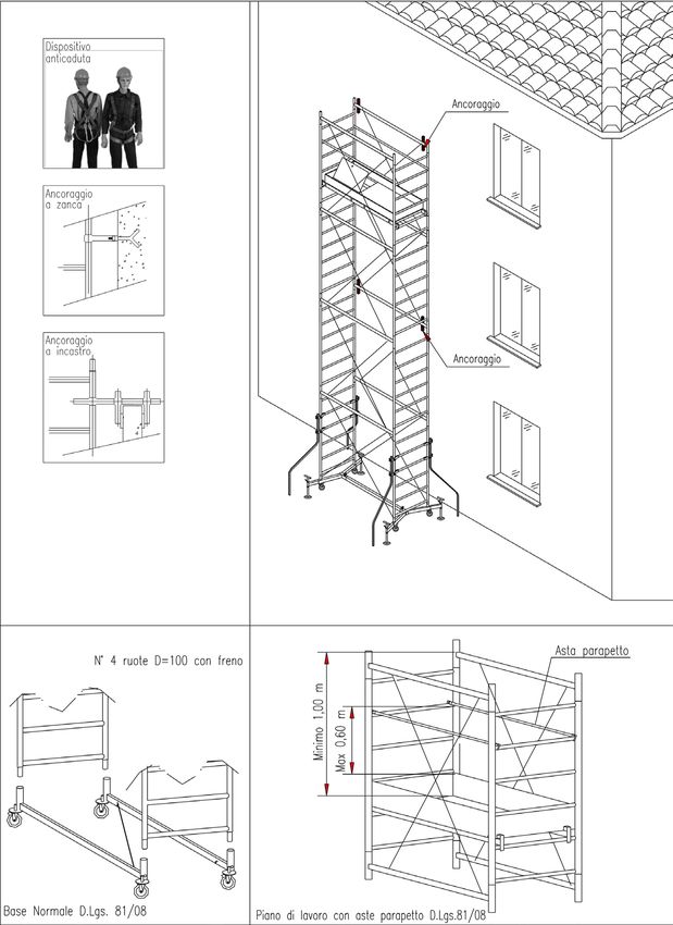
• Nella configurazione con altezza massima consentita del piano di lavoro di m 4,40, possono essere
montate sia la Base Normale EN, che la Base Normale D.Lgs. 81/08, (con n° 4 ruote D=100 mm tutte
dotate di freno.)
• Tutti i ponti conformi al D.Lgs. 81/08, ma non alla EN 1004, devono obbligatoriamente essere
ancorati ad una struttura fissa stabile ogni n° 2 alzate. Possono avere anche un solo piano di lavoro
montato, completo di tavole fermapiede e di parapetti, anche del tipo D.Lgs. 81/08 (costituiti da
n° 2 aste in acciaio con dispositivo antisfilo alle estremità.
• Per l’uso dei i parapetti tipo D.Lgs. 81/08, la distanza minima verticale tra i correnti ed il piano di
calpestio deve essere di m 1,00. I parapetti, devono essere collocati in posizione intermedia tra i
correnti e tavole fermapiede. (circa cm 60 dal piano)
• Le ruote della base devono essere frenate durante l’utilizzo e posizionate su pavimento già
perfettamente livellato.
• I piedini stabilizzatori, quando presenti, sfilati della massima quantità compatibile con gli ingombri
circostanti. Estrarre gli stabilizzatori fino la linea con la scritta MAX
• Le staffe stabilizzatrici sono elementi componenti della sezione di base, per ponti a torre montati
ad altezze superiori a m 7,00, devono sempre essere montate sia durante l’utilizzo che durante lo
spostamento, poste in senso verticale a 10 mm ca. dal terreno.
ACCESSO AI PIANI DI LAVORO:
E’ obbligatorio accedere ai piani di lavoro dall’interno della torre, i traversi dei telai laterali costituiscono
la scala di accesso. Le persone addette ad usare GRIM devono fare uso di un dispositivo anticaduta
collegato a cintura di sicurezza, che limiti la caduta libera a non più di m 0,70. Il dispositivo deve scorrere
lungo una fune, ancorata superiormente all’ultimo traverso dell’ultimo telaio laterale ed inferiormente
al blocco porta-ruote della base. Il dispositivo anticaduta, la cintura di sicurezza e la fune di trattenuta
devono essere di tipo omologato.
SEMIPIANO COD. 20635
H MAX 1,99 m
PARAPETTO tipo D.Lgs. 81/08
COD 20112
13www.marchetti.eu
COMPLETAMENTO INFORMAZIONI
Per quanto riguarda le ulteriori informazioni e precisamente:
portate / numero di piani contemporaneamente caricati / limiti del vento / identificazione dei
componenti / montaggio e smontaggio / stabilità / utilizzo / verifica / cura e manutenzione, vale
quanto riportato nel Manuale d’istruzioni EN 1298 IMitxen allegato.
14IT
REVISIONI SEMESTRALI
Ponte su ruote a torre Mod.
Revisione del
Verifica numerica dei componenti.
Pulizia componenti
Integrità dei componenti
Assenza zone ossidate
Integrità saldature
Lubrificazione viti di serraggio
Lubrificazione spinotti e manicotti
Efficienza ruote e dispositivi frenanti
Integrità piani di lavoro
Integrità parapetti
Integrità tavole fermapiede
Integrità Manuale d’istruzioni
Integrità adesivi con marcature di identificazione
Anomalie riscontrate
Elementi scartati da sostituire
Osservazioni
Responsabile della sicurezza Responsabile della sicurezza
(Nome e cognome per esteso) (Firma)
15www.marchetti.eu
REVISIONI SEMESTRALI
Ponte su ruote a torre Mod.
Revisione del
Verifica numerica dei componenti.
Pulizia componenti
Integrità dei componenti
Assenza zone ossidate
Integrità saldature
Lubrificazione viti di serraggio
Lubrificazione spinotti e manicotti
Efficienza ruote e dispositivi frenanti
Integrità piani di lavoro
Integrità parapetti
Integrità tavole fermapiede
Integrità Manuale d’istruzioni
Integrità adesivi con marcature di identificazione
Anomalie riscontrate
Elementi scartati da sostituire
Osservazioni
Responsabile della sicurezza Responsabile della sicurezza
(Nome e cognome per esteso) (Firma)
16IT
REVISIONI SEMESTRALI
Ponte su ruote a torre Mod.
Revisione del
Verifica numerica dei componenti.
Pulizia componenti
Integrità dei componenti
Assenza zone ossidate
Integrità saldature
Lubrificazione viti di serraggio
Lubrificazione spinotti e manicotti
Efficienza ruote e dispositivi frenanti
Integrità piani di lavoro
Integrità parapetti
Integrità tavole fermapiede
Integrità Manuale d’istruzioni
Integrità adesivi con marcature di identificazione
Anomalie riscontrate
Elementi scartati da sostituire
Osservazioni
Responsabile della sicurezza Responsabile della sicurezza
(Nome e cognome per esteso) (Firma)
17www.marchetti.eu
REVISIONI SEMESTRALI
Ponte su ruote a torre Mod.
Revisione del
Verifica numerica dei componenti.
Pulizia componenti
Integrità dei componenti
Assenza zone ossidate
Integrità saldature
Lubrificazione viti di serraggio
Lubrificazione spinotti e manicotti
Efficienza ruote e dispositivi frenanti
Integrità piani di lavoro
Integrità parapetti
Integrità tavole fermapiede
Integrità Manuale d’istruzioni
Integrità adesivi con marcature di identificazione
Anomalie riscontrate
Elementi scartati da sostituire
Osservazioni
Responsabile della sicurezza Responsabile della sicurezza
(Nome e cognome per esteso) (Firma)
18IT
REVISIONI SEMESTRALI
Ponte su ruote a torre Mod.
Revisione del
Verifica numerica dei componenti.
Pulizia componenti
Integrità dei componenti
Assenza zone ossidate
Integrità saldature
Lubrificazione viti di serraggio
Lubrificazione spinotti e manicotti
Efficienza ruote e dispositivi frenanti
Integrità piani di lavoro
Integrità parapetti
Integrità tavole fermapiede
Integrità Manuale d’istruzioni
Integrità adesivi con marcature di identificazione
Anomalie riscontrate
Elementi scartati da sostituire
Osservazioni
Responsabile della sicurezza Responsabile della sicurezza
(Nome e cognome per esteso) (Firma)
19www.marchetti.eu
www.marchetti.eu
MARCHETTI S.r.l.
Via Piemonte, 22 info@marchetti.eu
06062 Città della Pieve - Perugia - Italy www.marchetti.eu
20www.marchetti.eu
www.marchetti.eu
MARCHETTI S.r.l.
Via Piemonte, 22 info@marchetti.eu
06062 Città della Pieve - Perugia - Italy www.marchetti.eu
20ENG
SIX-MONTHLY SERVICE
Mobile access tower Mod.
Service of
Numerical verification of components
Cleaning of components
Integrity of components
Absence of oxidised areas
Integrity of welding
Lubrication of tightening screws
Lubrication of pins and sleeves
Efficiency of wheels and braking devices
Integrity of work platforms
Integrity of railings
Integrity of toe boards
Integrity of Instruction Manual
Integrity of stickers with identification markings
Faults detected
Discarded elements to be replaced
Notes
Health and Safety Officer Health and Safety Officer
(Full name) (Signature)
19www.marchetti.eu
SIX-MONTHLY SERVICE
Mobile access tower Mod. M
Service of S
Numerical verification of components
Cleaning of components
Integrity of components
Absence of oxidised areas
Integrity of welding
Lubrication of tightening screws
Lubrication of pins and sleeves
Efficiency of wheels and braking devices
Integrity of work platforms
Integrity of railings
Integrity of toe boards
Integrity of Instruction Manual
Integrity of stickers with identification markings
Faults detected F
Discarded elements to be replaced D
Notes N
Health and Safety Officer Health and Safety Officer
(Full name) (Signature)
18ENG
SIX-MONTHLY SERVICE
Mobile access tower Mod.
Service of
Numerical verification of components
Cleaning of components
Integrity of components
Absence of oxidised areas
Integrity of welding
Lubrication of tightening screws
Lubrication of pins and sleeves
Efficiency of wheels and braking devices
Integrity of work platforms
Integrity of railings
Integrity of toe boards
Integrity of Instruction Manual
Integrity of stickers with identification markings
Faults detected
Discarded elements to be replaced
Notes
Health and Safety Officer Health and Safety Officer
(Full name) (Signature)
17www.marchetti.eu
SIX-MONTHLY SERVICE
Mobile access tower Mod. M
Service of S
Numerical verification of components
Cleaning of components
Integrity of components
Absence of oxidised areas
Integrity of welding
Lubrication of tightening screws
Lubrication of pins and sleeves
Efficiency of wheels and braking devices
Integrity of work platforms
Integrity of railings
Integrity of toe boards
Integrity of Instruction Manual
Integrity of stickers with identification markings
Faults detected F
Discarded elements to be replaced D
Notes N
Health and Safety Officer Health and Safety Officer
(Full name) (Signature)
16ENG
SIX-MONTHLY SERVICE
Mobile access tower Mod.
ns
d Service of
Numerical verification of components
Cleaning of components
Integrity of components
Absence of oxidised areas
Integrity of welding
Lubrication of tightening screws
Lubrication of pins and sleeves
Efficiency of wheels and braking devices
Integrity of work platforms
Integrity of railings
Integrity of toe boards
Integrity of Instruction Manual
Integrity of stickers with identification markings
Faults detected
Discarded elements to be replaced
Notes
Health and Safety Officer Health and Safety Officer
(Full name) (Signature)
15www.marchetti.eu
ADDITIONAL INFORMATION M
With regard to additional information on:
capacities / number of work platforms allowed simultaneously / safety platform / wind limitations
/ identifying components / assembly and dismantling / stability / use / inspection / care and S
maintenance, the instructions in the EN 1298 IM-itxen manual attached
F
D
N
14ENG
ENG
GENERAL INFORMATION
d Tabel of configurations according to Italian D.Lgs 81/08
s; Mobile H. max H. max Tower N° min N° Type of Wall
tower Tower Work platforms Stabilizers base anchorage
D.Lgs. platform H>7m
81/08
n° 4 stan- every 2
Grim EU75 7,10 m 6,00 m n° 4 n° 1 Extractable
dard type towers
Norm.En- every 2
n° 4 stan-
Grim EU75 5,40 4,30 m n° 3 n° 1 Norm.D.l-
dard type towers
gs.81
f Configuration Grim EU 75, maximum working platform height allowed m 4,40, can be assembled with
Normal Base EN or Normal Base D.Lgs. 81/08 (n° 4 D=100 mm wheels, all with brake).
Can have only one working platform fitted, complete with toeboards and guardrails.
Guardrails can be D.Lgs. 81/08 composed of n° 2 steel bracing elements with blocking device at the
two parts. Placed to have the tower lateral bracing (upper guardrail) at a minimum of m 1.00, distant
from the working platform and the guardrails, in a intermediate position, between upper guardrail and
toeboard.
The wheels must be braked during use and positioned on a levelled ground.
- When present, pull the extractables up to the MAX line.
The stabilizers are component of the base, essential to higher than 7.00 m. They always must be present
on such towers, during use and in every movement. Put them vertically at about 10 mm to the ground.
of ACCESSING THE WORK PLATFORM:
It is obligatory to gain access to the work platforms from inside the tower; the lateral frames constitute
d the access ladder. Workers assigned to use the tower are required to use a fall arrest device attached
to a safety belt that limits the free-fall to a maximum of 0.7 metres. This device must run along a rope/
cable anchored above on the highest cross-piece of the highest lateral load bearing frame and below
on the wheel bearing section of the base. The fall arrest device, the safety belt and the supporting
ed
rope/cable must be type-approved. For the access to the work platforms using inclined ladders, the
as
descriptions are in the attached EN 1298 IM-itxen handbook apply.
of GUARDRAIL D.Lgs. 81/08
ly COD 20112
n
2 SEMI-PLATFORM COD. 20635
H MAX 1,99 m
13 13www.marchetti.eu
G
• Where not possible, materials may be lifted on the outside of the tower. Manual traction with
appropriate ropes/cables must still be used, the load must not exceed 50 kg, and it must be lifted Ta
vertically parallel to the tower, ensuring it remains within the area marked out by the stabilizers;
• The attachment or use of hoisting devices to lift materials is forbidden;
• It is forbidden to jump on the platforms;
• Bridging connections between the mobile access tower and any building are not allowed;
• The mobile access towers are not designed to be lifted off the ground or suspended in the air
(e.g. by means of a crane).
MOVING THE TOWER
• Mobile access towers can only be moved manually, on compact, smooth surfaces that are free of C
obstacles and in wind-free conditions; N
• Before moving the tower, reduce the tower’s total height to a maximum of 7.00 m, lift the adju- Ca
stable feet and the stabilizers off the ground by no more than 20 mm and disengage the wheel
brakes; G
t
• Normal walking pace should not be exceeded while moving the tower; fr
• Material and personnel should not be on the mobile access tower while it is being moved; to
• It is mandatory to keep a distance of at least 5.00 metres from power line; Th
• Once moved, engage the brakes on the four wheels, level the tower again and move the stabili- W
zers until perfectly in contact with the ground
Th
INSPECTION, CARE AND MAINTENANCE o
• After a certain number of uses, at the discretion of the operator, clean away the encrustations of A
cement, mortar, paint or other which will eventually build up on the various components;
It i
• Always keep the supplied clamping and adjusting screws, and the gudgeon/wrist pins and th
couplings of the various couplers well oiled; to
ca
o
• Before every assembly, check that all components are in perfect condition, replacing any damaged
ro
or worn components with others of the same type, which must be original components as
de
indicated by the manufacturer;
• While moving, transporting or storing the mobile access tower, take care to not subject any of
its components to loads which could cause permanent deformation, avoiding therefore badly
organised stacking and stacking together with materials of a different nature.
• Storage in a covered and sheltered place is recommended to reduce damage due to corrosion
over time.
12ENG
STABILITY
• Erect and use the mobile access towers only in the absence of windy conditions
• Fit the stabilizers, based on the configuration and height to be reached, ( see table)
• The maximum horizontal load capacity (e.g. applied by effect of work in progress in an adjacent
structure) is 25 kg, understood as the sum of the loads applied by the various operators working
on the tower;
• If the tower must be left unattended in position due to temporary interruption of work or windy
conditions, anchor it firmly to a fixed, stable structure;
• At the summit of the mobile access tower additional overlying structures should not be moun-
ted, and shielding of any kind, such as lattice, tarpaulin, etc., should not be fitted.
PRELIMINARY CHECKS
ti-
• Verify that the mobile access tower has been assembled in an upright position. Refer to the
supplier’s instructions regularly and follow them scrupulously to guarantee a perfect execution;
• Verify that there are no adverse weather conditions that could influence the safe use of the mobile
access tower (ice, rain, wind, etc.).
USE
t; • It is not allowed to increase the height of the decks by using ladders, boxes or other devices;
• it is mandatory to access the work surface from inside the tower, according to one of the three
possibilities:
• Vertical rung ladder; in this case, the lateral bearing frames, which have rungs with non-slip
surface and rung spacings compliant with the regulatory requirements, can be used for this
purpose
s,
• Inclined rung ladder
• Inclined step ladder
• All scaffolds in the tower be provided with lateral protection and toeboards, whethe used for
passage or work;
• Where possible, towers used outside of buildings, must be secured to the building or other
structure;
• Tools and materials must be lifted from the inside of the tower, from one platform to another,
through the trapdoors, using manual traction with appropriate ropes/cables.
11www.marchetti.eu
GRIM EU75 WITH NORMAL BASE S
• Place the 2 base braces on the ground in parallel position and with the latches facing inward; •
• Engage the 2 lateral frames into the housing on the ends of the base braces; •
• Continue the assembly by inserting the 2 connecting braces into the slots on top of the lateral •
frame uprights. Make sure the latches are facing inward;
• Install the diagonal bracing rods, hooking the ends onto the anti-slip latches on the braces;
•
• Fit the diagonal, hooking the ends onto the anti-slip latches on the base braces, and then lock
the 4 wheels with the brakes;
•
• Position the mobile access tower’s flat element on the fourth rung from the bottom of the first
two lateral frames.
• First, position the 2 long toeboards parallel to the walking surface. Make sure the stamped plate P
hooks on the ends of the toeboards face inwards. Now fit the 2 short toeboards into the respecti-
ve housings found in the long boards; •
• If the tower must be erected to a work platform height above m 1.80, the 4 stabilizers must be
fitted at this point;
•
• At this point at least one of the workers authorised to assemble the tower must put on a safety
belt and climb onto the work platform from the inside of the tower through the trapdoor;
• After having securely attached the end of the rope of the safety belt to one of the two already U
fitted connecting braces, the next two lateral frames can be attached and the tower can then
continue to be assembled following the same sequence of operations described up to this point; •
•
DISASSEMBLY
•
• To dismantle the mobile access tower, follow the assembly instructions in reverse order;
• Lower mobile access tower components from above using ropes, cables or other suitable means,
avoiding at all times abrupt impact with the ground. •
•
•
•
•
10ENG
• Position the mobile access tower’s elements on the fourth rung from the bottom of the first two
of lateral frames;
• First, position the 2 long toeboards parallel to the walking surface. Now fit the 2 short toeboards
into the respective housings found in the long boards;
• At this point at least one of the workers authorised to assemble the tower must put on a safety
belt and climb onto the work platform from the inside of the tower through the trapdoor;
• After having securely attached the end of the rope of the safety belt to one of the two already
o fitted connecting braces, the next two lateral frames can be attached and the tower can then con-
tinue to be assembled following the same sequence of operations described up to this point;
• If the tower must be erected to a work platform height above m 1,80 the 4 stabilizers must be
fitted at this point.
.
• arrange the stabilizers in open position. Fit the coupler to the tower’s upright on the rung weld
point at the height that allows accomodating the upper vertical portion of the stabilizer, Position
the stabilizer between the two couplers at an angle of about 120° in relation to the tower’s longer
side. Close the two front clampson on the stabilizer, making sure it rests firmly on the ground, and
then tighten the corresponding eyebolt nuts. Repeat the same sequence of operations for the
- other three tower uprights;
• As the tower is being assembled, pay careful attention to place the floor pieces in a position that
allows the person working at height the maximum possible safety and freedom of movement. The
person should have the possibility to anchor the safety belt worn easily;
le • Once the tower has been assembled, fit the work platforms, toeboards and lateral protections at
he the desired heights.
• The lateral protections are composed of 2 long frames and 2 short frames. The two frames must be
fitted first, parallel to the long sides of the tower. Rest them on the cross-pieces of the load bearing
frames, making sure the top pipe is one meter from the walking surface. Install the short frames
g parallel to the short side of the mobile access tower, hooking them up to the long guardrails at the
top end, and to the latches positioned on the latter at the bottom side;
• For passage platform use the guardrail bar, with anti-detachment device at the ends. Place the
bars on the rung and make sure that the hooks are in the correct anti-detachment position.
• During assembly, to raise the components for the upper section, it is advisable to use ropes or
s cables rated for the application, taking care never to pass up more than one component at a time;
• If access to the work platforms is to be gained by inclined rung or step ladders, these must be
attached with the two hooks at the top end to the cross piece on which the work platform;
n
x-
20
ls
g
9www.marchetti.eu
GENERAL INFORMATION
•
• The assembly and dismantling of the mobile access towers requires at least two people, both of
whom must be familiar with the assembly and use instructions.
• Damaged components must not be used; •
• Only original components indicated by the manufacturer may be used.
•
COMPLETE GUARDRAIL EN 1004
The lateral protection consists of two steel pipes frames joined by two steel cross elements that en- •
sure protection at both intermediate and top positions. They are hooked to the lateral cross-pieces to
avoid accidental detachment. Use as working top guardrail.
GUARDRAIL BAR •
Steel bar with device unthreading at either ends. To use as a protection in the passing workplatform.
•
If such workplatforms were used as staging or for working is obligatory the use of the EN 1004 guar-
drail.
SAFETY PLATFORM (D.Lgs. 09.04.2008 n° 81 Sez. IV - art. 128)
The Safety Platform (constructed in the same way as a normal work platform) is obligatory in mainte-
nance and repair works lasting more than 5 days and always obligatory in building works and must
be positioned under the work platform at a distance not greater than m 2.50. •
PRELIMINARY CHECKS
• The surface on which the tower is to be assembled and moved (if necessary) must be capable •
of supporting the weight. It must be perfectly levelled and capable of guaranteeing the
distribution of the load, preferably with the use of wooden planks or their equivalent;
•
• Ensure that the ground is free of obstacles of any kind;
• The assembly operations can only be undertaken in the absence of wind;
• Check that all of the parts, accessories and safety equipment are near at hand before assembling
the mobile access tower;
• The uprightness of mobile access towers must be controller by spirit level. •
ASSEMBLY/DISASSEMBLY GRIM EU75 EXTRACTABLE BASE •
• Join the two bearing sections with the one base connecting brace using the two handgrip screws
supplied; •
• Before tightening the screws fully, position the first two lateral frames;
• Tighten the screws, engage the brakes in the four wheels and proceed to the horizontal extraction
of the adjustable feet to the maximum length the surrounding surface space allows; Pull the ex-
tractables up to the MAX line.
• Level the base section using the screws on the feet, taking care to raise all the wheels at least 20
mm off the ground; once levelled, tighten the lock nuts;
• Continue the assembly by inserting the 2 connecting braces, taking care to position the pawls
towards the inside and the labels towards the outside.
• Install the diagonal bracing rods, hooking the ends onto the anti-slip latches on the connecting
braces;
8ENG
GRIMEU75 EN 1004 CONFIGURATION
NORMAL BASE EXTRACTABLE BASE
INSIDE AND OUTSIDE
NORMAL BASE
CONFIGURATIONS A1 A1T A2 A2T A3
H max mobile tower m 2,00 2,85 3,70 4,55 5,40
H max work platform m 1,00 1,85 2,70 3,55 4,40
H tower ( H= 1,70 m) n° 1 1 2 2 3
H tower ( H= 0,85 m) n° 0 1 0 1 0
Work platform n° 1 1 1 1 1
Complete guardrail n° 1 1 1 1 1
Guardrail bars n° 0 0 0 0 0
Stabilizers-30 n° 0 0 4 4 4
Base section normal n° 1 1 1 1 1
EXTRACTABLE BASE
CONFIGURATIONS B1 B1T B2 B2T B3 B3T B4
H max m 2,00 2,85 3,70 4,55 5,40 6,25 7,10
H max work platform m 1,00 1,85 2,70 3,55 4,40 5,25 6,00
H tower ( H= 1,70 m) n° 1 1 2 2 3 3 4
H tower ( H= 0,85 m) n° 0 1 0 1 0 1 0
Work platform n° 1 1 1 1 1 2 2
Complete guardrail n° 1 1 1 1 1 1 1
Guardrail bars n° 0 0 0 0 0 2 2
Stabilizers-30 n° 0 0 0 4 4 4 4
Base section extractable n° 1 1 1 1 1 1 1
7www.marchetti.eu
G
For configurations with H=0,85 m terminal tower A1T-A2T-B1T-B2T-B3T, add the
following elements:
Cod. Components elements Wei- CONFIGURATIONS
ght
Kg A1T A2T B1T B2T B3T
20597 EXTRACTABLE BASE
10 20569 Bearing frame 3,50 2 2 2 2 2
8 20570 Connecting brace 2,10 2 2 2 2 2
11 20572 Terminal diagonal brace 0,90 4 4 4 4 4
COMPONENTS ELEMENTS
4
2
3 1
Extractable base
EN 1004 16
with brake and 4 wheels Ø 150 15
5
6
Normal base Guardrail
EN 1004
with brake and 4 wheels Ø 150
23
22 21
20
Guardrail bars
18
Work platform
8 17
8
7
10
11
9
Tower H=1,70 m Terminal tower H=0,85m
6ENG
IDENTIFICATION
EN 1004 Class “3” (2,00 KN/mq)
s: Overall permitted load: kg 190
Maximum number of surfaces loaded simultaneously: 2
Table of elements composing the configurations
Cod. Component Elements Wei- CONFIGURATIONS
ght
Kg A1 A2 A3 B1 B2 B3 B4
20596 EXTRACTABLE BASE
1 20573 Wheel-bearing section for ext.base 9,00 0 0 0 2 2 2 2
2 20574 Base brace 3,30 0 0 0 1 1 1 1
3 20318 Extractable adjustable foot 3,50 0 0 0 4 4 4 4
4 30522 Handgrip screw M12x80 0,14 0 0 0 2 2 2 2
ed 20641 NORMAL BASE
5 20642 Wheel - bearing section - normal 4,50 2 2 2 0 0 0 0
base
to
he 6 20644 Diagonal - 160 0,90 1 1 1 0 0 0 0
ll. 20595 TOWER
is 7 20568 Bearing frame 7,60 2 4 6 2 4 6 8
a 8 20570 Connecting brace 2,10 2 4 6 2 4 6 8
9 20571 Diagonal brace 1,20 4 8 12 4 8 12 16
21082 WORK PLATFORM STEEL
20 Platform w/trapdoor - 165 1 1 1 1 1 1 2
21 21082 Long toeboard - 165 3,26 2 2 2 2 2 2 4
22 Short toeboard - 75 1,03 2 2 2 2 2 2 4
20752 COMPLETE GUARDRAILS
15 20643 Long guardrail - 165 4,90 2 2 2 2 2 2 2
16 20786 Short guardrail - 75 1,70 2 2 2 2 2 2 2
GUARDRAIL BARS
23 20112 Guardrail bar Grimeu75 1,76 0 0 0 0 0 0 2
20713 STABILIZERS
17 20766 Stabilizer - 30 5,40 0 4 4 0 0 4 4
18 31619 Stabilizers coupler - 30 0,50 0 8 8 0 0 8 8
21559 STABILIZERS
17 21559 Telescopic stabilizer-30 5,40 0 4 4 0 0 4 4
5www.marchetti.eu
GENERAL INFORMATION I
Access to work platform E
Access to the work platform can only take place inside the tower using one of the following methods: O
M
- vertical rung ladder, composed of uprights on the side frames of the structure
- inclined rung ladder, internal
- inclined step ladder, internal.
Maximum heights of the configuration EN 1004
Normal base: max height m 1,80 without stabilizers / m 4,40 with stabilizers
Extractable base: max height m 2,70 without stabilizers / m 6,00 with stabilizers
There are two types of stabilizers: Normal-35 and Super-35.
Normal-35 stabilizers must be always fitted inside of buildings.
Outside the buildings they can be fitted for work platform heights inferior to m 5,00 in wind exposed
conditions.
When the tower on wheels are mounted next to a wall (ex. building ) such as to constitute a barrier to
the wind, the Normal brackets can be mounted as an alternative to the Supers. In the latter case, the
wall-side brackets must be oriented towards the outside of the tower in a position parallel to the wall.
Super-35 stabilizers must be fitted to towers with work platform above m 5,00 and when the tower is
completely exposed to the wind (for example, in the middle of a square next to a structure, such as a
light pole, that does not act as a wind barrier, etc.).
Minimum height clearance between work platforms is: m 1,90.
Maximum vertical distance between work platform: m 4,20. 2
Maximum vertical distance between the ground and the first level: m 4,60. 2
2
1
1
2
1
1
1
4ENG
REFERENCE STANDARDS
- Leg. Decree 09.04.2008 no. 81 (O.G. no. 101 dated 30.04.08) “Consolidating act on health and
safety in the workplace”.
- EN 1004 (July 2005) “Mobile access and working towers) composed of prefabricated elements.
Materials, dimensions, design loads, safety and performance requirements”;
- EN 1298 (February 1996) “Mobile access towers. Regulations and guidelines for preparation of an
instructions manual”;
- Leg. Decree 06.09.2005 no. 206 (O.G. no. 235 on 08.10.05 – Ordinary Supplement no. 162)
“Consumers’ Code”.
DESIGNATION, CLASS, CAPACITY
GRIM EU75 on extractable base, working tower EN 1004 – 3 – 6 / 6 XXCD.
GRIM EU75 on normal base, working tower EN 1004 – 3 – 4,40 / 4,40 XXCD.
manufactured in compliance with Leg. Decree 81/08 and Technical Standard EN 1004;
Class of loads distributed uniformly equal to “3” (2.0 KN/m2);
- Maximum height permitted of the working surface equal to m 5,00 sboth outside and inside
buildings. Inside is intended as without wind
- The overall load permitted for each tower is therefore 190 kg.
- The maximum number of surfaces loaded at the same time is 2.
- The sum of the loads relating to each surface must not exceed the overall value of the load
permitted for the scaffolding.
DECLARATION OF CONFORMITY
MARCHETTI s.r.l. Città della Pieve (PG) Italy
Declares:
• that the mobile tower called GRIM EU75 was manufactured in compliance with Leg. Decree
09.04.2008 no. 81 and in particular the Technical Standard EN 1004 (July 2005)
• that it is manufactured in compliance with the prototype which has surpassed rigidity testing,
pursuant to Appendix “A” of the Technical Standard EN 1004 (2005) and that it was subject, with
a positive outcome, with the ASSESSMENT as outlined in point 13 of the Technical Standard EN
1004 (2005) at the:
UNIVERSITY OF PERUGIA - Department of Industrial Engineering
Certificate no. Marc 85
• the identification marking is outlined on all specimens of the products and on the Instructions
Manual drafted according to specifications in Technical Specification EN1298 (point 9 of the
Technical Standard EN 1004).
Marchetti s.r.l.
3www.marchetti.eu
ATTENTION: R
-
• Read and understand this manual in its entirety.
• Follow the instructions as indicated. -
• Before any installation, verify the integrity of each individual -
component.
Do not use damaged or not whole components -
The mobile access tower is made according to the standards.
Any changes made by others invalidate the manifacturer’s D
responsibility. G
G
m
Cl
-
WARRANTY -
All MARCHETTI products are covered by the company’s official guarantee, pursuant to -
applicable norms. The guarantee is immediately effective and is ratified by the invoice -
accompanying the goods. A product found to be faulty is guaranteed. We shall accept
no responsibility for products used incorrectly or damaged during use or transport. The
product must be returned with its original packaging, undamaged; it shall be covered by D
guarantee if it has not been dismantled, modified or tampered with.
COPYRIGHT
This documentation is protected by copyright. Any copying or reproduction, including
extracts thereof,and the reproduction of images(even in a modified state),in only •
permitted with the written authorisation of the manufacturer.
•
•
M
2ENG
European standard EN 1004 Instructions for use
and maintenance
www.marchetti.eu
MOBILE ACCESS TOWER
GRIM EU
The products identified in this handbook have been ma-
nufactured by MARCHETTI s.r.l. With QUALITY SYSTEM
MANAGEMENT, certified by Tuv Italia, in accordance
with ISO 9001
CUSTOMER ASSISTANCE DOCUMENT
NR. 146 REV. 0 OF 27/08/2020
Code 11301
Instructions Manual EN 1298 – IM – it x en
Mobile access towers must only be used for finishing, maintenance and similar works. This instructions
manual contains important instructions on use, maintenance and safety of the mobile access tower;
the operator must be completely aware of them before use. Strictly complying with this manual
means working in compliance with the provisions of the current standard on health and safety in the
workplace Leg. Decree. 09.04.2008 no. 81.
MARCHETTI S.r.l.
Via Piemonte, 22 info@marchetti.eu
06062 Città della Pieve - Perugia - Italy www.marchetti.eu
1Puoi anche leggere