CALCOLATRICE PER CIRCUITI STAMPATI - KICAD DOCS
←
→
Trascrizione del contenuto della pagina
Se il tuo browser non visualizza correttamente la pagina, ti preghiamo di leggere il contenuto della pagina quaggiù
Calcolatrice per Circuiti Stampati
Calcolatrice per Circuiti Stampati                    ii

                                     27 aprile 2021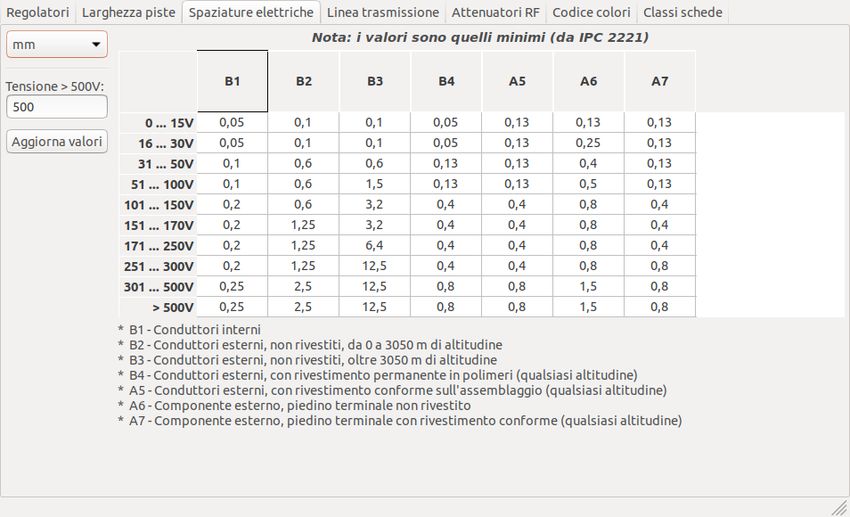
Calcolatrice per Circuiti Stampati                                                                                                    iii

Indice

1   Introduzione                                                                                                                      1

2   Calcolatrici                                                                                                                      1
    2.1   Regolatori . . . . . . . . . . . . . . . . . . . . . . . . . . . . . . . . . . . . . . . . . . . . . . . . . . . . . . .    1
    2.2   Larghezza piste . . . . . . . . . . . . . . . . . . . . . . . . . . . . . . . . . . . . . . . . . . . . . . . . . . . .     2
    2.3   Spaziature elettriche . . . . . . . . . . . . . . . . . . . . . . . . . . . . . . . . . . . . . . . . . . . . . . . . . .   3
    2.4   Linea di trasmissione . . . . . . . . . . . . . . . . . . . . . . . . . . . . . . . . . . . . . . . . . . . . . . . . .     3
    2.5   Attenuatori RF . . . . . . . . . . . . . . . . . . . . . . . . . . . . . . . . . . . . . . . . . . . . . . . . . . . .      5
    2.6   Codice colori . . . . . . . . . . . . . . . . . . . . . . . . . . . . . . . . . . . . . . . . . . . . . . . . . . . . .     5
    2.7   Classi schede . . . . . . . . . . . . . . . . . . . . . . . . . . . . . . . . . . . . . . . . . . . . . . . . . . . . .     6
          2.7.1    Performance Classes . . . . . . . . . . . . . . . . . . . . . . . . . . . . . . . . . . . . . . . . . . . . .      6
          2.7.2    PCB Types . . . . . . . . . . . . . . . . . . . . . . . . . . . . . . . . . . . . . . . . . . . . . . . . . .      6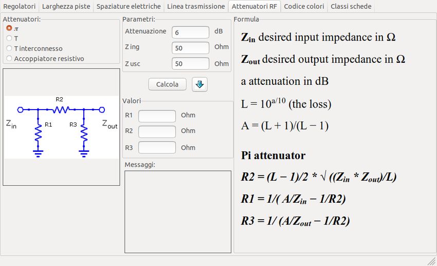
Calcolatrice per Circuiti Stampati                                                                                             1/7

Manuale di riferimento
Copyright
Questo documento è coperto dal Copyright © 2019 dei suoi autori come elencati in seguito. È possibile distribuirlo e/o modi-
ficarlo nei termini sia della GNU General Public License (https://www.gnu.org/licenses/gpl.html), versione 3 o successive, che
della Creative Commons Attribution License (https://creativecommons.org/licenses/by/3.0/), versione 3.0 o successive.
Contribuitori
Heitor de Bittencourt. Mathias Neumann
Traduzione
Marco Ciampa , 2019.
Feedback
Si prega di inviare qualsiasi rapporto bug, suggerimento o nuova versione a:

• Sulla documentazione di KiCad: https://gitlab.com/kicad/services/kicad-doc/issues
• Sul software KiCad: https://gitlab.com/kicad/code/kicad/issues

• Sulla traduzione del software di KiCad: https://gitlab.com/kicad/code/kicad-i18n/issues

Data di pubblicazione e versione del software
March 05 2020

1     Introduzione

The KiCad PCB Calculator is a set of utilities to help you find the values of components or other parameters of a layout. The
Calculator has the following tools:

• Regolatori
• Larghezza piste
• Spaziature elettriche

• Linee di trasmissione
• Attenuatori RF
• Codice colori

• Classi schede

2     Calcolatrici

2.1   Regolatori

Questa calcolatrice serve ad aiutare a trovare i valori delle resistenze necessarie per i regolatori lineari, inclusi quelli a bassa
caduta.
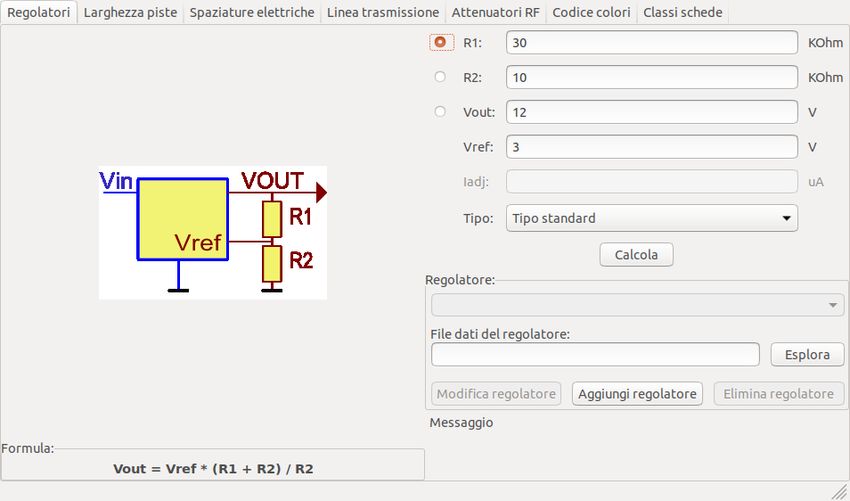
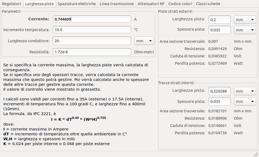
Calcolatrice per Circuiti Stampati                                                                                              2/7

For the Standard Type, the output voltage Vout as a function of the reference voltage Vref and resistors R1 and R2 is given by:

For the 3 terminal type, there is a correction factor due to the quiescent current Iadj flowing from the adjust pin:

Questa corrente solitamente è sotto i 100 uA e può essere ignorata con cautela.
To use this calculator, enter the parameters of the regulator Type, Vref and, if needed, Iadj, select the field you want to calculate
(one of the resistors or the output voltage) and enter the other two values.

2.2   Larghezza piste

The Track Width tool calculates the trace width for printed circuit board conductors for a given current and temperature rise. It
uses formulas from IPC-2221 (formerly IPC-D-275).
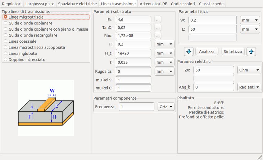
Calcolatrice per Circuiti Stampati                                                                                           3/7

2.3   Spaziature elettriche

This table helps finding the minimum clearance between conductors.
Each line of the table has a minimum recomended distance between conductors for a given voltage (DC or AC peaks) range. If
you need the values for voltages higher than 500V, enter the value in the box in the left corner and press Update Values.

2.4   Linea di trasmissione

La teoria delle linee di trasmissione è una pietra miliare nell’insegnamento dell’ingegneria RF e delle microonde.
Nella calcolatrice si può scegliere tra diversi tipi di linee ed i loro parametri speciali. I modelli implementati dipendono dalle
frequenze e quindi non corrispondono con i modelli più semplici a frequenze abbastanza alte.
Calcolatrice per Circuiti Stampati                                                                                    4/7

Questa calcolatrice è fortemente basata su Transcalc.
I tipi di linee di trasmissione ed i riferimenti dei loro modelli matematici sono elencati di seguito:

• Microstrip line:

  – H. A. Atwater, “Simplified Design Equations for Microstrip Line Parameters”, Microwave Journal, pp. 109-115, November
    1989.

• Guida d’onda coplanare.

• Guida d’onda coplanare con piano di massa.
• Rectangular waveguide:

  – S. Ramo, J. R. Whinnery and T. van Duzer, "Fields and Waves in Communication Electronics", Wiley-India, 2008, ISBN:
    9788126515257.

• Linea coassiale.
• Coupled microstrip line:

  – H. A. Atwater, “Simplified Design Equations for Microstrip Line Parameters”, Microwave Journal, pp. 109-115, November
    1989.
  – M. Kirschning and R. H. Jansen, "Accurate Wide-Range Design Equations for the Frequency-Dependent Characteristic of
    Parallel Coupled Microstrip Lines," in IEEE Transactions on Microwave Theory and Techniques, vol. 32, no. 1, pp. 83-90,
    Jan. 1984. doi: 10.1109/TMTT.1984.1132616.
  – Rolf Jansen, "High-Speed Computation of Single and Coupled Microstrip Parameters Including Dispersion, High-Order
    Modes, Loss and Finite Strip Thickness", IEEE Trans. MTT, vol. 26, no. 2, pp. 75-82, Feb. 1978.
  – S. March, "Microstrip Packaging: Watch the Last Step", Microwaves, vol. 20, no. 13, pp. 83.94, Dec. 1981.

• Stripline.
• Doppino ritorto.
Calcolatrice per Circuiti Stampati 5/7 2.5 Attenuatori RF With the RF Attenuator utility you can calculate the values of the resistors needed for different types of attenuators: • Pigreco • T • T interconnesso • Accoppiatore resistivo To use this tool, first select the type of attenuator you need, then enter the desired attenuation (in dB) and input/output impedances (in Ohms). 2.6 Codice colori Questa calcolatrice aiuta nella traduzione delle barre di colore presenti sulle resistenze nel loro valore. Per usarla, basta selezionare la tolleranza della resistenza: 10%, 5% o minore o uguale al 2%. Per esempio: • Giallo viola rosso oro: 4 7 x100 ±5% = 4700 Ohm, 5% di tolleranza • 1kOhm, 1% tolleranza: marrone nero nero marrone marrone
Calcolatrice per Circuiti Stampati                                                                                           6/7

2.7     Classi schede

2.7.1   Performance Classes

In IPC-6011 have been three performance classes established
Class 1 General Electronic Products Includes consumer products, some computer and computer peripherals suitable for ap-
plications where cosmetic imperfections are not important and the major requirement is function of the completed printed
board.
Class 2 Dedicated Service Electronic Products Includes communications equipment, sophisticated business machines, instrumen-
ts where high performance and extended life is required and for which uninterrupted service is desired but not critical. Certain
cosmetic imperfections are allowed.
Class 3 High Reliability Electronic Products Includes the equipment and products where continued performance or performance
on demand is critical. Equipment downtime cannot be tolerated and must function when required suchas in life support items or
flight control systems. Printed boards in this class are suitable for applications where high levels of assurance are required and
service is essential.

2.7.2   PCB Types

In IPC-6012B there are also 6 Types of PCB defined:

• Printed Boards without plated through holes (1)

  – 1 Single-Sided Board

• And Boards with plated through holes (2-6)

  – 2 Double-Sided Board
  – 3 Multilayer board without blind or buried vias
  – 4 Multilayer board with blind and/or buried vias
  – 5 Multilayer metal core board without blind orburied vias
  – 6 Multilayer metal core board with blind and/orburied vias
Calcolatrice per Circuiti Stampati 7/7
Puoi anche leggere