MANUALE D'USO E MANUTENZIONE USER'S MANUAL - ALANERA MANUBRIO INTEGRATO ALANERA INTEGRATED HANDLEBAR - DEDA ELEMENTI
←
→
Trascrizione del contenuto della pagina
Se il tuo browser non visualizza correttamente la pagina, ti preghiamo di leggere il contenuto della pagina quaggiù
MANUALE D’USO
E MANUTENZIONE
USER’S MANUAL
Ver. 0 - Aprile/April 2017 ©Deda Elementi
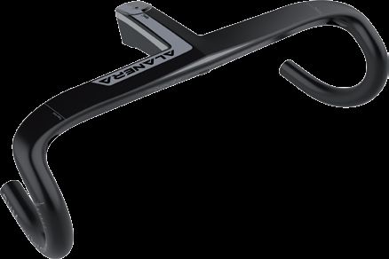
Alanera Manubrio Integrato
Alanera Integrated Handlebar
(MOD. 2018 / MY2018)
AlaneraCongratulazioni per il vostro nuovo manubrio Deda Elementi. Leggere e seguire attentamente le seguenti istruzioni per un corretto utilizzo. Un errato montaggio e un incorretta applicazione delle seguenti istruzioni può danneggiare il prodotto che non sarà più coperto dalla garanzia, danneggiare la bicicletta o causare un incidente. Per una appropriata installazione del prodotto sono richiesti specifici attrezzi e una adeguata esperienza, si raccomanda dunque che il prodotto sia installato dai punti vendita ufficiali Deda Elementi o da personale qualificato nel montaggio di biciclette. Congratulations on your new Deda Elementi handlebar. Please read these instructions carefully and follow them for correct use. An improper installation or wrong application of the instructions could damage the product, that will be no more covered under warranty, damage the bicycle or cause an accident resulting in injury or death. Since specific tools and experience are necessary for proper installation, it is recommended that the product be installed by an official Deda Elementi dealer or a qualified bicycle technician.
INDICE
ITA
       INFORMAZIONI GENERALI DI SICUREZZA______________________________________ pag. 4

       GARANZIA_________________________________________________________________ pag. 5

       PACKAGING _______________________________________________________________ pag. 6

       ISTRUZIONI DI MONTAGGIO__________________________________________________ pag. 7

       MONTAGGIO SUPPORTO GARMIN _____________________________________________ pag. 9

      CONTENTS
eng    GENERAL SAFETY INFORMATION_____________________________________________ pag. 10

       WARRANTY________________________________________________________________ pag. 11

       PACKAGING _______________________________________________________________ pag. 12

       HANDLEBAR INSTALLATION__________________________________________________ pag. 13

       GARMIN MOUNT INSTALLATION________________________________________________ pag. 15
INFORMAZIONI GENERALI DI SICUREZZA
È responsabilità dell’utilizzatore controllare regolarmente il prodotto per
determinarne la necessità di manutenzione o di sostituzione di parti. I manubri in
carbonio e le sue parti sono prodotti soggetti all’usura durante il normale utilizzo
della bicicletta, si raccomanda quindi all’utilizzatore di ispezionare il prodotto
periodicamente per localizzare eventuali danni. In caso di problemi o dubbi,
sospendere l’uso della bicicletta e far ispezionare il prodotto da un punto vendita
ufficiale Deda Elementi o da personale qualificato nel montaggio di biciclette.
Questo prodotto è stato sviluppato e concepito per essere utilizzato su strade
asfaltate. In caso di utilizzo su strade non asfaltate o fuori strada il prodotto
può subire danni che compromettono il funzionamento fino a causare gravi
incidenti per l’utilizzatore.
Dopo un eventuale caduta o incidente è indispensabile sospendere l’utilizzo
della bicicletta e far effettuare un accurata ispezione del prodotto da un punto
vendita Deda Elementi.
Leggere attentamente l’intero Manuale d’Uso e conservarlo in un posto
sicuro per una futura consultazione.
ita
4GARANZIA
Deda Elementi garantisce che tutti i prodotti sono liberi da difetti nei materiali o di
lavorazione per un periodo di due anni dall’acquisto originale a meno di quanto
stabilito nella polizza di garanzia. La garanzia è valida solo sull’acquisto di un prodotto
originale Deda Elementi.
2.1 LIMITI ALLA GARANZIA
In caso di vendita o cessione del prodotto, la garanzia sarà considerata valida
solamente all’interno del periodo di due anni dalla data di acquisto.
La garanzia non copre danni causati da modifiche, trasformazioni anche parziali,
adattamenti di qualsiasi tipo, manomissioni o manutenzione effettuata da
personale non autorizzato, utilizzo del prodotto al di fuori delle normali condizioni
d’uso su strade asfaltate. Sono altresì esclusi danni provocati da urti, collisioni,
cadute e comunque verificatesi per cause violente e/o accidentali.
La garanzia non copre gli eventuali difetti estetici quali: opacizzazione,
screpolature, scoloriture o altro che le superfici delle ruote dovessero presentare
durante l’utilizzo, a seguito di lavaggi con acqua in pressione, con l’impiego
di solventi o prodotti chimici, benzine o altri simili, utilizzati per la pulizia della
bicicletta.
In caso di imperfezioni, difetti o danni riscontrati sul prodotto, l’utilizzatore dovrà
dare comunicazione al punto vendita entro 10 (dieci) giorni: trascorso tale
termine la garanzia non sarà più considerata valida.
Deda Elementi si riserva il diritto di modificare parzialmente o totalmente i suoi
prodotti, le istruzioni e la garanzia senza alcun preavviso per il Cliente.
5PACKAGING
Nel packaging del prodotto da voi acquistato sono presenti i seguenti componenti:
(1) Curva manubrio
(2) Vite compressione serie sterzo M6x30mm, 1pz
(3) Tappo alluminio Aero
(4) Barilotto filettato, 1pz
(5) Vite attacco M5x22mm, 2pz
(6) Distanziale Aero da 5 mm (Top spacer), 1pz
(7) Distanziale Aero da 10 mm, 1pz
(8) Distanziale Aero da 20 mm, 1pz
(9) Coperchietto serie sterzo (Top cover), 1pz
(10) Supporto Garmin® compatibile serie 500&800
(11) Deda Cover Nylon
(12) Vite Cover M5x, 2pz
(1) Curva manubrio
(10) Supporto Garmin® (2) Vite
compressione
(3)
Tappo Aero
(12) Viti Cover
(11) Deda Cover (4)
Barilotto
(6) Distanziale 5 mm
(5) Viti
M5x22mm
(7) Distanziale 10 mm
(8) Distanziale 20 mm
(9) Coperchietto serie sterzo
ita
Barilotto asimmetrico,
parte inferiore identificata da un foro
6ISTRUZIONI DI MONTAGGIO
EXPANDER
VITE COMPRESSIONE SERIE STERZO
DISTANZA MINIMA 3 mm
TAPPO AERO DISTANZA MAX. 4 mm
VITE ESPANSIONE EXPANDER
COPPIA MAX. SERRAGGIO 3 Nm
(vite interna)
VITE ATTACCO
COPPIA MAX. SERRAGGIO 5 Nm
DISTANZIALE AERO 5 mm CANNOTTO FORCELLA
OBBLIGATORIO
DISTANZIALE AERO 10 mm
OPZIONALE
DISTANZIALE AERO 20 mm
OPZIONALE
COPERCHIETTO SERIE STERZO AERO
OBBLIGATORIO
1. Se compatibile, sostituite il coperchietto della serie sterzo originale montata
sulla bicicletta con il coperchietto Alanera incluso (9). Il coperchietto Alanera
è compatibile con tubi sterzo da 46mm di diametro esterno.
2. Inserite i distanziali Aero nel cannotto forcella al di sopra del coperchio
serie sterzo rispettando le seguenti istruzioni:
− il distanziale Aero da 5 mm (6) indicato con la scritta top spacer, è obbligatorio
e deve sempre essere posizionato direttamente sotto l’attacco manubrio.
− I distanziali Aero da 10 mm (7) e da 20 mm (8) sono opzionali e consentono
di posizionare la curva manubrio all’altezza desiderata.
− La distanza tra il bordo superiore dell’attacco e il bordo superiore del cannotto
forcella deve essere obbligatoriamente compresa tra i 3 e i 4 mm.
Se necessario tagliate il cannotto della forcella secondo le istruzioni del
costruttore e assicuratevi che non ci siano intagli e/o irregolarità sulla
superficie tagliata.
− Non mettete i distanziali al di sopra dell’attacco manubrio.
ATTENZIONE: Il bordo inferiore dell’attacco, che lavora in una zona dove
non c’è l’expander, tenderà a ovalizzare e intagliare il cannotto forcella, con
gravi rischi per la vostra incolumità.
73. Inserite la curva nel cannotto forcella con le viti di fissaggio laterali
dell’attacco allentate in modo che l’attacco possa scorrere lungo il cannotto.
4. Inserite l’expander (non incluso) nel cannotto forcella sino a battuta e
serrare la vite di espansione dello stesso con una coppia massima di 3 Nm.
ATTENZIONE: Assicuratevi che l’expander che utilizzate abbia una
lunghezza superiore all’altezza del collarino dell’attacco in modo tale che
entrambe le viti posteriori dell’attacco insistano su una porzione di cannotto
completamente occupata dall’expander stesso.
5. Montate il tappo Aero dedicato (3) e serrate la vite di compressione per
precaricare i cuscinetti e azzerare il gioco assiale nella serie sterzo.
ATTENZIONE: Un serraggio troppo elevato può danneggiare i cuscinetti a
sfera che potrebbero bloccarsi sotto sforzo. Rispettate scrupolosamente la
coppia di serraggio raccomandata nel manuale di uso e manutenzione della
serie sterzo che impiegate.
6. Assicuratevi che la curva sia allineata alla direzione di marcia e serrate
alternativamente entrambe le viti posteriori dell’attacco nel barilotto, al
massimo di ½ giro alla volta, sino a raggiungere una coppia minima di
serraggio di 4 Nm.
Se l’attacco manubrio non dovesse essere sufficientemente serrato,
aumentate la coppia di serraggio fino ad un massimo di 5Nm.
Verificate il fissaggio dell’attacco manubrio, che non deve ruotare sul
cannotto forcella.
ATTENZIONE: La coppia di serraggio delle viti di chiusura dell’attacco deve
essere la minima che garantisca la non-rotazione dello stesso sul cannotto
forcella (Max. 5 Nm). Una coppia inutilmente superiore genera un deleterio
stato di compressione radiale sul cannotto forcella che può fessurarsi e/o
tranciarsi senza preavviso.
ita
8MONTAGGIO SUPPORTO GARMIN®
1. Rimuovete la Cover (11) svitando le due viti poste nella parte inferiore.
2. Inserite il supporto Garmin® (10) nell’apposito spazio e fissatelo alla curva
manubrio con le stesse due viti. Serrate le viti con una coppia di serraggio
consigliata di 3Nm.
3. Verificate che il supporto sia installato correttamente prima di utilizzare il
Garmin®. Questo modello è compatibile con le serie 500 e 800.
CONTATTI
Per qualsiasi domanda o informazione tecnica potete contattare direttamente
Deda Elementi visitando il sito internet www.dedaelementi.com e tramite
l’indirizzo email info@dedaelementi.com
Deda Elementi s.r.l si riserva il diritto di modificare senza preavviso il contenuto
del presente manuale garantendo sempre la disponibilità della versione più
aggiornata sul sito internet nell’area download.
9GENERAL SAFETY INFORMATION
It is the user’s responsibility to examine the product on a regular basis to
determine the need for service or replacement. Wheels and their components are
products that wear from normal use of the bicycle, for that reason we recommend
cyclists to regularly inspect their bicycle and parts in order to detect any damage.
If any doubts or problems occurr, discontinue riding the wheels and have them
inspected by an official Deda Elementi dealer or a qualified bicycle technician.
This handlebar has been designed and intened to be used on normal paved
surfaces. In case of use on not paved surfaces or off-road, the product can
be subjected to damages, loose its functioning and cause serious accidents
and injury for the user.
If any bicycle fall or accident occur, discontinue riding the bicycle and have it
inspected carefully by an official Deda Elementi dealer or a qualified bicycle
technician. The use of any damaged bicycle part can cause serious accidents
and injury for the user.
Read the whole User’s Manual carefully and keep it in a safe place for later
reference.
eng
10WARRANTY
Deda Elementi warrants that all Deda Elementi to be free from defects in materials
or workmanship for a period of two years after original purchase unless otherwise
stated on the Warranty policy.
The Warranty is valid for the purchase of an origianl Deda Elementi product only.
2.1 LIMITS OF WARRANTY
In case of sale or product cession, the Warranty will be considered valid for a
two years period only from the original purchace.
The Warranty doesn’t cover damages caused by modifications, even
small; any kind of adaptions or alterations; maintenance performed by an
unauthorized people; use of the product outside the normal riding conditions
on paved road surfaces. The Warranty doesn’t cover even damages caused
by impacts, collisions, falls that may occurr for accidental reasons.
The Warranty doesn’t cover aesthetic defetcs like: matting, chap, fading or
other phenomenons that may occur to the wheels during the use and after
the bicycle cleaning using water in pressure, solvents or similar products,
petrol.
In case of imperfections, defetcs or damages found on the product, the user
is asked to entry in contact with the dealer within 10 (ten) days; after this
periond ends the Warranty will be no more considered eligible.
Deda Elementi S.r.l. reserves the right to modify partially or completly the
products, instructions and warranty without any notice to the customer.
11PACKAGING
The product package you have just purchased contains the following parts:
(1) Handlebar
(2) Headset compression screw M6x30mm, 1pc
(3) Aero Top cap
(4) Barrel-nut, 1pc
(5) Stem screw M5x22mm, 2pcs
(6) 5 mm Aero Spacer (Top spacer), 1pc
(7) 10 mm Aero Spacer, 1pc
(8) 20 mm Aero Spacer, 1pc
(9) Aero headtube cover (Top cover), 1pc
(10) Integrated Garmin® mount (for 500&800 series)
(11) Nylon Deda Cover
(12) Cover screw M5x, 2pcs
(1) Integrated hndlebar
(10) Garmin® mount (2) Compression
screw M6x30mm
(3) Aero
Top cap
(12) Cover screw
(11) Deda Cover (4)
Barrel-nut
(6) 5 mm Top spacer
(5) Stem screw
M5x22mm
(7) 10 mm spacer
(8) 20 mm spacer
(9) Top cover
eng
Asymmetric barrel-nut,
lower side identified by hole
12TECHNICAL SPECIFICATIONS:
EXPANDER
HEADSET COMPRESSION SCREW
MINIMUN GAP 3 mm
AERO TOP CAP MAX GAP 4 MM
EXPANDER EXPANSION BOLT
MAX TORQUE 3 Nm
(internal screw)
STEM SCREW
MAX TORQUE 5 Nm
5 mm AERO SPACER FORK STEERER
REQUIRED
10 mm AERO SPACER
OPTIONAL
20 mm AERO SPACER
OPTIONAL
AERO HEADTUBE COVER
REQUIRED
1. Remove the original top cover from your bicycle frame and replace with the
Alanera top cover (9), if compatible. The Alanera Top cover is intended for
46mm headtube frame.
2. Install spacers on the fork steerer above the top cover following below
instructions:
− It is mandatory to use the 5 mm Aero spacer (6) and it must be installed
directly under the handlebar stem.
− 10 and 20 mm Aero spacers are optional. They can be used to adjust the
stack height according to the desired handlebar position.
− The gap between the top of the handlebar stem and the top of the fork steerer
must be within a range of 3 to 4 mm. If necessary, cut fork steerer according
to manufacturer’s instructions.
Ensure there are no sharp burrs on the steerer tube.
WARNING: Do not put spacers above the stem. The lower edge of the stem,
which applies pressure on an area not supported by the expander, will cause
fork steerer ovalization and dangerous cuts and serious risks for your safety.
133. Install the handlebar on the steerer tube. Loosen the rear stem screws so that
the handlebar stem can slide along the fork steerer.
4. Install the expander (not included) in the fork steerer until it stops, and tighten
the expansion bolt at maximum of 3 Nm.
WARNING: Make sure that the expander has enough length to ensure the stem
rear screws seat on the expander portion of the fork steerer. This will reduce the
risk of fork steerer notching while tightening the stem rear bolts.
5. Install the Aero top cap and tighten the compression bolt to preload the
headset bearings and adjust the headset play.
WARNING: Overtightening can damage the ball bearings that could get stuck
under stress.
Follow carefully the tightening torque recommended in the operation and
maintenance manual of the headset you use.
6. Ensure handlebar is aligned straight in relation to the direction of travel.
Tighten the two rear stem screws into the barrel–nut alternately, turning ½ turn
at a time, until a minimum torque of 4Nm is reached. If the handlebar stem is not
tight enough, increase the torque up to a maximum of 5 Nm. Please check the
handlebar stem, which should not rotate on the fork steerer.
WARNING: Always use a calibrated torque wrench to tighten the bolts. Use the
minimum stem bolts tightening torque required to ensure that the handlebar
stem does not rotate on the fork steerer (Max. 5 Nm). An unnecessarily high
torque generates a dangerous state of radial compression on the fork steerer
which can cracks and/or break without notice.
eng
14GARMIN MOUNT INSTALLATION
1. Remove the nylon Deda Cover (11) for non-Garmin® users unscrewing the two
screws.
2. Insert the Garmin® mount (10) and fix it to the handlebar with the same two
screws.
Tighten the bolts starting with a suggested minimum torque of 3 Nm.
3. Check that the Garmin® mount has been correctly fixed before using your
Garmin® computer. This model is compatible with 500 and 800 series.
CONTACTS
For any question or technical information please contact Deda Elementi by
visiting the website at www.dedaelementi.com and through the email address
info@dedaelementi.com.
Deda Elementi s.r.l reserves the right to modify without notice the content of
this manual always guaranteeing the avalaibility of the updated versions on the
website dowanload area.
15www.dedaelementi.com
Deda Elementi S.r.l.
Via Leonardo Da Vinci, 21/23
26010 Campagnola Cremasca (CR) - Italia
Tel. +39 0373 750 129
Fax +39 0373 751 105
www.dedaos.com.tw
Deda OS
No.8, Lane 150-30, Sec. 3, Xitun Rd.,
Xitun Dist.
Taichung City 407, Taiwan (R.O.C.)
tel: +886-4-24623436
fax: +886-4-24623430
Deda Elementi USA
dedausa@dedaelementi.com
#ridededaPuoi anche leggere