SMART CONTROL PLUS - Salupo
←
→
Trascrizione del contenuto della pagina
Se il tuo browser non visualizza correttamente la pagina, ti preghiamo di leggere il contenuto della pagina quaggiù
ITA/ENG
                                                               rev.1 24/06/2020

     SMART CONTROL PLUS
                            SC100.29/xx

    MANUALE DI ISTRUZIONE E INSTALLAZIONE
    INSTRUCTION AND INSTALLATION MANUAL

           Dispositivo per telecontrollo GPRS con display

            Device for GPRS remote control with display

CUSTOMER SERVICE
+39 (0) 941.1820216        customer.service@salupoquadri.com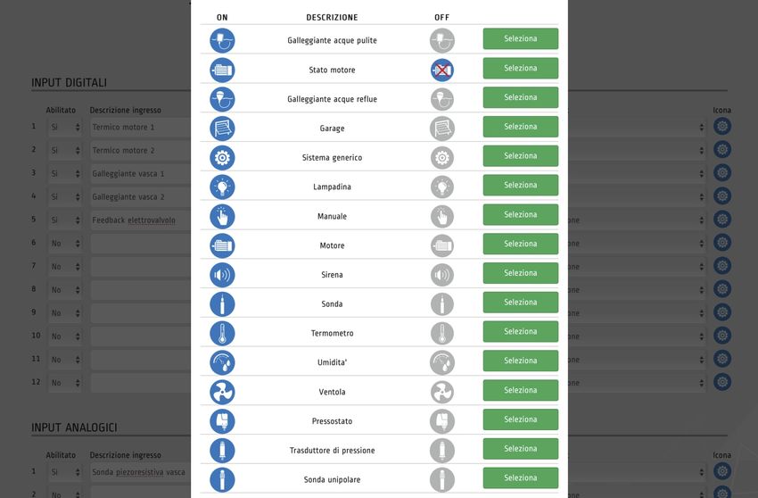
INDICE

1. Istruzioni generali per l’installazione                       3

2. Avvertenze                                                    3

3. Schema di collegamento
   Schema di collegamento SC100.29/xx                            4

4. Piattaforma Salupo Connect                                    5

5. Configurazione espansione GPRS                               6

6. Registrazione su Salupo Connect                               8

7. Programmazione su Salupo Connect                              9

8. Monitoraggio su Salupo Connect                               12

9. Schermate setup                                              13

10. Funzionamento                                               13

11. Smaltimento di vecchi apparecchi elettrici ed elettronici   26

12. Dichiarazione di conformità                                 26

                                                  2
1. ISTRUZIONI GENERALI PER L’INSTALLAZIONE                                                                         ITALIANO

Assicurarsi che la linea sia protetta, secondo le normative, in funzione dell'applicazione. Accertarsi
che i carichi collegati al relé non siano superiori a 5A per uscita.
Installare il quadro in ambienti adatti al suo grado di protezione IP65. Per il fissaggio dell'involucro,
utilizzare le staffe per i box 03-04. Nell'effettuare il fissaggio dell'involucro fare molta attenzione a non
toccare o danneggiare i vari componenti. Eliminare qualsiasi tipo di impurità metallica e/o plastica
che dovesse casualmente cadere all'interno dell'involucro (viti, rondelle, polvere…). Effettuare i
collegamenti elettrici rispettando gli schemi di collegamento.
Nel fissare i cavi sulle morsettiere, adoperare attrezzi di giuste misure e dimensioni evitando di
danneggiare i morsetti metallici e le relative sedi. Prima di qualsiasi operazione da effettuare
all'interno, escludere l'alimentazione generale.
Le operazioni di regolazione all'interno del quadro devono essere svolte da personale qualificato. In
caso di intervento delle protezioni verificarne la causa prima del ripristino.
In caso di necessità sostituire i vari componenti solo con altri aventi le stesse caratteristiche e portate
di quelli originali.

È compito dell'installatore verificare l'apparecchiatura dopo l'installazione nonostante
questa sia già stata sottoposta regolarmente a prove dal costruttore.

Il costruttore declina ogni responsabilità per sinistri a cose o persone dovuti a manomissioni
delle apparecchiature da parte di personale non autorizzato o da carenze nella manutenzione.
e riparazione.

2. AVVERTENZE

               SCOSSE ELETTRICHE

               Rischio di scosse elettriche se non si osserva quanto prescritto.

               PERICOLO

               Rischio di lesioni personali e materiali se non si osserva quanto prescritto.

               AVVERTENZA

               Prima di installare e utilizzare questo prodotto leggere attentamente questo manuale nella sua totalità.
               L’installazione e la manutenzione devono essere realizzate da personale qualificato e secondo le normative in
               vigore. Il costruttore non è responsabile di danni causati per un uso improprio o proibito di questo dispositivo e
               nemmeno di danni causati da una non corretta installazione e manutenzione dello stesso. L’utilizzo di pezzi
               non originali, la manipolazione o l’uso improprio annulleranno la garanzia.

               AVVERTENZA

               Assicurarsi che l’assorbimento dei carichi collegati non siano superiori a 5A per ogni uscita.
               Installare il dispositivo solo in ambienti adeguati al suo grado di protezione IP 65. Nel caso di operazioni dentro
               il quadro utilizzare strumenti adeguati per evitare di danneggiare i morsetti.

               PERICOLO
               Prima di realizzare qualsiasi intervento assicurarsi che il quadro non sia alimentato. Non compiere nessuna
               operazione quando il quadro è aperto. Il dispositivo deve essere collegato a una messa a terra efficiente.
               Per fissare la carcassa utilizzare i fori appropriati presenti nel fondo per non danneggiare i componenti interni
               e eliminare qualsiasi scarto di lavoro dentro il quadro.

                                                              3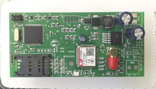
3. SCHEMA DI COLLEGAMENTO

Schema di collegamento SC100.29/xx

                                    ESPANSIONE COMUNICAZIONE

           C 1 2 3 4 C 5 6 7 8 C 9 10 11 12 C 1 2 3 4                      NC NO COM NC NO COM NC NO COM NC NO COM   +   -    L1   N
            DIGITAL INPUT   DIGITAL INPUT   DIGITAL INPUT   INPUT 4-20mA    OUT 1      OUT 2     OUT 3    OUT 4      24Vdc 230Vac

  LEGENDA
                                                                                                                         L1                 N
  C                     COMUNE INGRESSI
  1.....12              INPUT DIGITALI
                                                                                                               LINEA DI ALIMENTAZIONE
  1-2-3-4               INPUT 4-20mA                                                                        230 Vac 50/60 Hz (SC100.29/230)
  OUT 1 - 2 - 3 - 4     USCITE CONTATTO PURO COM. NO. NC. (MAX 5A)
                                                                                                                  24 Vdc (SC100.29/24)

                                                                                                                                       Max 2.5 mm²
                                            Max 10 mm²                                                                                    (M3)
                                                                                                 8,3 mm                                0,5Nm
                                               (M4)
      10 mm                                 0,8Nm

                                                                            4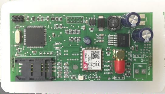
4. PIATTAFORMA SALUPO CONNECT                                                      ITALIANO

SALUPO CONNECT è un servizio di monitoraggio remoto che consente la supervisione
ed il controllo degli impianti da un qualsiasi computer o dispositivo mobile tramite i più
comuni web browser.
La configurazione e le operazioni di manutenzione, spesso svolte in ambienti poco
agevoli o confortevoli, sono ora più semplici per tutti i prodotti Salupo dotati di moduli di
comunicazione GPRS o Ethernet.
Di fatto è possibile collegarsi ad essi tramite il sito www.salupo.it, accessibile da
smartphone, tablet e PC con un qualsiasi web browser.
Tramite SALUPO CONNECT si possono modificare i parametri di setup, cambiare lo
stato di funzionamento dei motori e verificare le misurazioni rilevate dai dispositivi.
Inoltre è possibile visualizzare gli eventi e scaricare i dati d’interesse per consentire
un'analisi accurata.

Il sistema in questione ha le seguenti caratteristiche:
  Possibilità di selezionare la lingua tra: Italiano, Inglese, Francese e Spagnolo;
  Personalizzazione del profilo: permette l'accesso a clienti ed installatori con profili
  dedicati;
  Facile utilizzo: è facile da installare, utilizzare ed è indipendente da qualsiasi
  configurazione di rete, non è necessario un IP statico né modificare le impostazioni del
  router;
  Monitoraggio proattivo: il quadro invia alla piattaforma la lettura dei propri parametri, lo
  stato delle pompe, i livelli, le misure elettriche e le anomalie;
  Segnalazione allarmi: tutti gli utenti registrati nell'impianto riceveranno un avviso via
  e-mail in caso di allarme. Questo permette l'individuazione di guasti e
  malfunzionamenti in tempi celeri;
  Diagnosi semplificata: quando il cliente segnala un guasto o un'anomalia, il personale
  che si occupa del customer care e/o l'installatore ha una visibilità immediata dei
  parametri dell'impianto e la possibilità di consultare lo storico degli eventi;
  Riduzione dei costi di gestione: grazie al controllo remoto è possibile interagire con
  l'impianto in qualsiasi momento e con la funzione dei timer, è possibile impostare
  diversi avviamenti programmati.

                                              5
5. CONFIGURAZIONE ESPANSIONE GPRS

     SLOT SIM                       LED DI STATO SEGNALE                  CONNETTORE FEMMINA
                                                                             SMA ANTENNA

Prima di procedere con la registrazione del prodotto sul portale SALUPO CONNECT
(https://www.salupo.it) bisogna configurare in modo corretto il modulo GPRS.
Prima di dare inizio alla configurazione assicurarsi che la SIM abbia la richiesta del PIN disattivata.

CONFIGURAZIONE
1 - Inserire la SIM nell’apposito slot

           CHIUSO                APERTO

2 - Collegare l’antenna nel connettore femmina SMA

3 - Accendere il quadro

                                         ON

                                                   6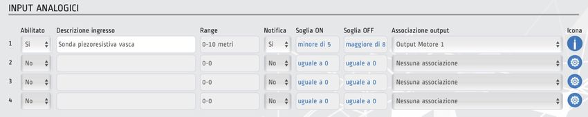
5. CONFIGURAZIONE ESPANSIONE GPRS                                                           ITALIANO

4 - Attendere che il modulo GPRS dia avvio alla ricerca del segnale. Il LED DI STATO SEGNALE
emetterà un lampeggio ogni 800ms.

5 - Attendere che il modulo GPRS si sia agganciato alla rete GSM. Il LED DI STATO SEGNALE
emetterà un lampeggio ogni 3 secondi.

6 - Attivare la connessione dati inviando un SMS alla SIM installata   SMART CONTROL PLUS
sull’espansione GPRS con l’APN del proprio operatore telefonico
con la seguente dicitura:
6. REGISTRAZIONE SU SALUPO CONNECT

Per accedere al portale bisogna effettuare la registrazione compilando tutti i campi richiesti e
inserendo la matricola pervenuta in precedenza:

Una volta effettuata la registrazione l’account sarà creato e verrà inviato un link di attivazione
all’indirizzo e-mail che si è inserito, per verificare che sia un indirizzo valido .

                                               8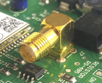
7. PROGRAMMAZIONE SU SALUPO CONNECT                                                                ITALIANO

Inserendo le proprie credenziali di accesso (e-mail e password) è possibile accedere alla piattaforma.

Una volta eseguito l'accesso, l'utente vede la lista di tutti gli impianti registrati con il relativo stato
(Online/Offline), il relativo funzionamento (Regolare/Allarme) e può aggiungere altri impianti non
ancora registrati.

                                                                   Matricola
                              SC100.29   SMART CONTROL PLUS GPRS   ABCDEF      Online   Regolare

Cliccando sull’impianto desiderato si accede nella sezione "Monitoraggio".

                                                       9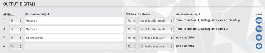
7. PROGRAMMAZIONE SU SALUPO CONNECT

Da quì è possibile accedere nella sezione "Dettagli impianto" cliccando sull’apposito pulsante.

           Dettagli impianto           Monitoraggio               Setup quadro                     Storico

Il menù “Dettagli impianto” permette di:
1. Inserire i dati relativi dell’impianto (il nome impianto è obbligatorio);

2. Cliccando su Dissocia da questo impianto apparirà un messaggio pop-up il quale richiede la conferma per
dissociare l’utente corrente dall’impianto.

3. Per collegare un nuovo utente basta cliccare sul pulsante                     Aggiungi utente             e si verrà
reindirizzati sulla pagina "Scheda utente".

                                                      10
7. PROGRAMMAZIONE SU SALUPO CONNECT ITALIANO
Da quì è possibile accedere nella sezione “Setup quadro” cliccando sull’apposito pulsante.
Dettagli impianto Monitoraggio Setup quadro Storico
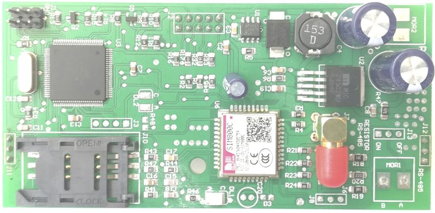
Il menù “Setup quadro” permette di:
1. Programmare gli ingressi digitali;
Ogni ingresso digitale può essere associato ad un’uscita digitale, in modo da gestirla al variare del
segnale di ingresso.
2. Programmare gli ingressi analogici;
Ogni ingresso analogico ha la possibilità di stabilire il range del sensore installato e selezionare l’unità
di misura più appropriata; impostare l’attivazione della soglia (ON/OFF) e associarlo ad un’uscita
digitale.
3. Programmare le uscite digitali;
Ogni uscita digitale può essere programmata per essere controllata manualmente o tramite gli
ingressi associati.
117. PROGRAMMAZIONE SU SALUPO CONNECT
Seleziona icona.
Cliccando sull’icona degli ingressi o delle uscite selezionate si apre un pop-up dove sarà possibile
selezionare l’icona più appropriata.
8. MONITORAGGIO SU SALUPO CONNECT
Da quì è possibile accedere nella sezione “Monitoraggio” cliccando sull’apposito pulsante.
Dettagli impianto Monitoraggio Setup quadro Storico
La sezione “Monitoraggio” permette di:
1. Visualizzare lo stato degli ingressi digitali;
2. Visualizzare lo stato degli ingressi analogici;
3. Visualizzare e gestire lo stato delle uscite digitali.
129. SCHERMATE SETUP ITALIANO
IDIOMA
ESPANOL V .1.0
ACCENSIONE
QUADRO LANGUE
FRANCAISE V.1.0
ON
LANGUAGE
ENGLISH V.1.0
SETUP PREMI QUESTA SCHERMATA
PAGE + PAGE 10s LINGUA VISUALIZZA LA MATRICOLA
ITALIANO V.1.0 DELL’IMPIANTO.
SARÀ PRESENTE SOLO
DOPO AVER ESEGUITO
+ LA PROGRAMMAZIONE
RIPORTATA NEL CAPITOLO 5.
LINGUA MATRICOLA
ITALIANO V.1.0 xxxxxx
10. FUNZIONAMENTO
ACCENSIONE
QUADRO
ON
SETUP PREMI
PAGE + PAGE 10s
QUESTE SCHERMATE VISUALIZZANO
QUESTE SCHERMATE
LO STATO DEGLI INGRESSI ANALOGICI 4-20mA
VISUALIZZANO LO STATO
IN PERCENTUALE. I TRATTINI INDICANO
DEGLI INGRESSI DIGITALI
CHE L’INGRESSO È ASSENTE
DI 1 2 3 4 5 6 7 DI 8 9 10 11 12 ANALOG INPUT ANALOG INPUT
A1 48% A2 ---% A3 57% A4 12%
QUESTA SCHERMATA
VISUALIZZA LO STATO
DELLE USCITE DIGITALI
DO 1 2 3 4
LO STATO DEL SEGNALE È ALTO
LO STATO DEL SEGNALE È BASSO
13INDEX
1. General instructions for installing 15
2. Warnings 15
3. Wiring diagram
Wiring diagram SC100.29/xx 16
4. Salupo Connect platform 17
5. GPRS expansion configuration 18
6. Registration on Salupo Connect 20
7. Programming on Salupo Connect 21
8. Monitoring on Salupo Connect 24
9. Setup screens 25
10. Functioning 25
11. Disposal of electrical & electronic equipment 26
12. Declaration of conformity 26
141. GENERAL INSTRUCTIONS FOR INSTALLING ENGLISH
Make sure power supply is protected up to standard depending on application. Make sure that the
loads connected to the relay do not exceed 5A per output.
Install the control panel in an environment appropriate to its IP65 degree of protection. To fix the
enclosure, use the brackets for the boxes 03-04 and the special predispositions for the remaining
boxes. In order to fix the box, use the appropriate holes which are present or suggested on the
bottom. Pay particular attention to not touching or damaging any components while fixing the box.
Eliminate whatever metal and/or plastic impurity which could happen to fall inside the box (screws,
washers, dust…).
When connecting electric cables, follow the wiring diagrams.
When fixing the cables in the terminal board use tools of correct size to avoid damaging the metal
feed clamps and their sockets.
Before acting upon anything inside, disconnect power supply. Regulation procedures must be
carried out by qualified personnel. In case protections intervene verify the cause of the problem
before resetting.
If necessary substitute the various components only with those having the same characteristics and
components as the originals.
It is the installer' s duty to verify the device after the installation although it has already
undergone regular testing by the manufacturer.
The manufacturer is released from all responsibilities for accidents to things or people, which
derive from misuse of the devices by unauthorized personnel or from lack of maintenance
and repair.
2. WARNINGS
ELECTRIC SHOCKS
Risk of electric shocks if not complied with the requirements.
DANGER
Risk of personal injury and property if not complied with the requirements.
WARNING
Before installing and using the product read this book in all its parts. Installation and maintenance must be
performed by qualified personnel in accordance with current regulations.
The manufacturer will not be held responsible for any damage caused by improper or prohibited use of this
control panel and is not responsible for any damages caused by an incorrect installation or maintenance of the
plant. The use of non-original spare parts, tempering or improper use, make the product warranty null.
WARNING
Make sure that the absorption of the connected loads does not exceed 5A for each output. Install the control
panel in an environment appropriate to its IP 65 degree of protection.
To operate inside the control panel use tools of correct size to avoid damaging the sockets.
DANGER
Before carrying out any intervention, make sure that the control panel is not powered.
Do not attempt operations when the control panel is open.The control panel must be connected to an efficient
earthing system.
In order to fix the box use the appropriate holes present on the bottom, don't damage internal components and
eliminate any working debris inside the box.
In the case of protections eliminate the cause of the malfunction before the restoration.
3
153. WIRING DIAGRAM
Wiring diagram SC100.29/xx
EXPANSION COMMUNICATION
C 1 2 3 4 C 5 6 7 8 C 9 10 11 12 C 1 2 3 4 NC NO COM NC NO COM NC NO COM NC NO COM + - L1 N
DIGITAL INPUT DIGITAL INPUT DIGITAL INPUT INPUT 4-20mA OUT 1 OUT 2 OUT 3 OUT 4 24Vdc 230Vac
KEY
L1 N
C COMMON INPUTS
1.....12 DIGITAL INPUTS
POWER SUPPLY
1-2-3-4 4-20mA INPUTS 230 Vac 50/60 Hz (SC100.29/230)
OUT 1 - 2 - 3 - 4 PURE CONTACT COM. NO. NC. (MAX 5A) OUTPUTS
24 Vdc (SC100.29/24)
Max 2.5 mm²
Max 10 mm² (M3)
8,3 mm 0,5Nm
(M4)
10 mm 0,8Nm
3
164. SALUPO CONNECT PLATFORM ENGLISH
SALUPO CONNECT is a remote monitoring service that allows supervision and control of the
systems from any computer or mobile device through the most common web browsers.
The configuration and maintenance operations, often carried out in difficult or uncomfortable
environments, are now simpler for all Salupo products equipped with GPRS or Ethernet
communication modules.
Indeed, you can connect to Salupo devices through the www.salupo.it site, accessible from a on
smartphone, tablet and PC via a common web browser.
Through SALUPO CONNECT you can change the setup parameters, change the operation status of
the motors and check the measurements read by the devices.
The device events and data can be viewed and downloaded to allow a more accurate analysis.
The system has the following features:
Possibility to select the language: Italian, English, French and Spanish;
Profile customization: allows access to customers and installers with dedicated profiles;
Simple use: it is easy to install, use and independent of any network connection. No static
IP is required and even modify the router settings;
Proactive monitoring: the control panel sends the reading of its parameters to the
platform, the pumps status, the levels, electrical measurements and the anomalies;
Alarm signaling: in the even of an alarm all the users registered in the system will receive
the notification via e-mail. This allows the identification of faults and malfunctions in quick
times;
Simplified diagnosis: when the customer reports a fault or anomaly, the personnel
responsible for the customer care and/or the installer has immediate visibility of the
system parameters and and the possibility to consult the event history;
Reduction of management costs: thanks to the remote control it is possible to interact with
the system at any time and with the timer function, it is possible to set different
programmed start-ups.
3
175. GPRS EXPANSION CONFIGURATION
SLOT SIM LED DI STATO SEGNALE CONNETTORE FEMMINA
SMA ANTENNA
Before proceeding with registering the product on the SALUPO CONNECT portal
(https://www.salupo.it), the GPRS module must be configured correctly. Before starting the
configuration make sure that the SIM has the PIN request disabled.
CONFIGURATION
1 - Insert the SIM in the appropriate slot
LOCK OPEN
2 - Connect the antenna to the SMA female connector
3 - Ignition control panel
ON
185. GPRS EXPANSION CONFIGURATION ENGLISH 4 - Wait for the GPRS module to start searching for the signal. The SIGNAL STATUS LED will flash every 800ms. 5 - Wait for the GPRS module to connect to the GSM network. The SIGNAL STATUS LED will flash every 3 seconds. 6 - Activate the data connection by sending an SMS to the SMART CONTROL PLUS installed SIM on GPRS expansion with the APN of your telephone operator with the following wording:
6. REGISTRATION ON SALUPO CONNECT

To access the portal, you must register by filling in all the required fields and entering the serial number
received previously:

                            Login        Registration

                                               New user registration

                             Name:

                               Name:

                             Surname:

                               Surname:

                             e-mail:

                               e-mail:

                             Password:

                               Password:

                             Repeat password:

                               Repeat password:

                             Product serial number:

                               Product serial number:

                                    I have read and accept the privacy policy

                             Are you registered? Access
                                                        Sign in

Once registered, the account will be created and an activation link will be sent to the e-mail address
you entered, to verify that it is a valid address.

                                                         20
7. PROGRAMMING ON SALUPO CONNECT ENGLISH
By entering your login credentials (e-mail and password) you can access the platform.
Registration
Reserved area
You are not registered Sign in
Remember username Access
I forgot the password
Once logged in, the user sees the list of all registered systems with their status (Online / Offline), their
operation (Regular / Alarm) and can add other systems not yet registered.
English info@salupoquadri.com
Serial number
SC100.29 SMART CONTROL PLUS GPRS ABCDEF Online Regular
By clicking on the desired system you access the "Monitoring" section.
217. PROGRAMMING ON SALUPO CONNECT
From here you can access the "System details" section by clicking on the appropriate button.
System details Monitoring Control panel Setup History
The "System details" menu allows you to:
1. Enter the data relating to the system (the system name is mandatory);
2. By clicking on Dissociate from this system a pop-up message will appear requesting confirmation to
dissociate the current user from the system.
3. To connect a new user just click on the button Add user and you will come redirected to
the "User Card" page.
227. PROGRAMMING ON SALUPO CONNECT ENGLISH
From here you can access the "Control Panel Setup" section by clicking on the appropriate button.
System details Monitoring Control panel Setup History
The "Control Panel setup" menu allows you to:
1. Program the digital inputs;
Each digital input can be associated with a digital output, in order to manage it as the input signal
changes.
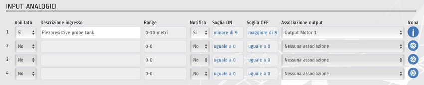
2. Program the analog inputs;
Each analog input has the ability to establish the range of the sensor installed and select the most
appropriate unit of measurement; set the activation of the threshold (ON / OFF) and associate it with a
digital output.
3. Program the digital outputs;
Each digital output can be programmed to be controlled manually or through the associated inputs.
237. PROGRAMMING ON SALUPO CONNECT
Select icon.
By clicking on the icon of the selected inputs or outputs, a pop-up opens where you can select the
most appropriate icon.
8. MONITORING ON SALUPO CONNECT
From here you can access the "Monitoring" section by clicking on the appropriate button.
System details Monitoring Control panel Setup History
The "Monitoring" section allows you to:
1. View the status of the digital inputs;
2. View the status of the analog inputs;
3. View and manage the status of the digital outputs.
249. SETUP SCREENS ENGLISH
IDIOMA
ESPANOL V .1.0
IGNITION
CONTROL PANEL
LANGUE
FRANCAISE V.1.0
ON
LANGUAGE
ENGLISH V.1.0
SETUP PRESS THIS SCREEN SHOWS THE
PAGE + PAGE 10s LINGUA SERIAL NUMBER OF THE PLANT.
ITALIANO V.1.0 IT WILL BE PRESENT ONLY
AFTER HAVING PERFORMED
+ PROGRAMMING REPORTED
IN CHAPTER 5.
LANGUAGE SERIAL NUMBER
ENGLISH V.1.0 xxxxxx
10. FUNCTIONING
IGNITION
CONTROL PANEL
ON
SETUP PRESS
PAGE + PAGE 10s
THESE SCREENS SHOW THE STATUS
THESE SCREENS
OF THE 4-20mA ANALOG INPUTS
SHOW THE STATUS
IN PERCENTAGE. THE DASHES INDICATE
OF THE DIGITAL INPUTS
THAT THE INPUT IS ABSENT
DI 1 2 3 4 5 6 7 DI 8 9 10 11 12 ANALOG INPUT ANALOG INPUT
A1 48% A2 ---% A3 57% A4 12%
THIS SCREEN SHOWS
THE STATUS OF THE
DIGITAL OUTPUTS
DO 1 2 3 4
THE SIGNAL STATUS IS HIGH
THE SIGNAL STATUS IS LOW
2511. SMALTIMENTO DI VECCHI APPARECCHI ELETTRICI ED ELETTRONICI
DISPOSAL OF ELECTRICAL & ELECTRONIC EQUIPMENT
Questo simbolo sul prodotto o sul suo imballo indica che esso non può essere trattato come rifiuto domestico.
Al contrario, dovrà essere portato ad un punto di raccolta determinato per il riciclaggio degli apparecchi elettrici ed elettronici,
come ad esempio:
- punti vendita, nel caso si acquisti un prodotto nuovo simile a quello da smaltire
- punti di raccolta locali (centri di raccolta rifiuti, centri locali di riciclaggio, ecc...).
AssicurandoVi che il prodotto sia smaltito correttamente, aiuterete a prevenire potenziali conseguenze negative per l'ambiente e
la salute, che potrebbero essere causate da un inadeguato smaltimento di questo prodotto. Il riciclaggio dei materiali aiuterà a
conservare le risorse naturali. Per informazioni più dettagliate riguardo il riciclaggio di questo prodotto, contattate per cortesia il
Vs. ufficio locale, il Vs. servizio di smaltimento rifiuti domestici o il negozio dove avete acquistato questo prodotto.
This symbol on the product or its packaging indicates that it shall not be treated ashousehold waste. Instead, it shall
be handed over to the applicable collection point for the recycling of electrical and electronic equipment,
such as for example:
- sales points, in case you buy a new and similar product
- local collection points (waste collection centre, local recycling center, etc...).
By ensuring this product is disposed of correctly, you will help prevent potential negative consequence for the environment and
human health, which could otherwise be caused by inappropriate waste handing of this product. The recycling of materials will
help to preserve natural resources. For more detailed information about recycling of this product, please contact your local city
office, your house hold waste disposal service or the shop where you purchased the product.
12. DICHIARAZIONE DI CONFORMITA’
DECLARATION OF CONFORMITY
Il costruttore:
Salupo S.r.l.
C/da Pietra di Roma - Via Vicolo VI, n°2
98070 Torrenova (ME)
Dichiara che:
I dispositivi SMART CONTROL PLUS
sono conformi ai requisiti di protezione in materia di sicurezza (bassa tensione) e di compatibilità elettromagnetica specifici
previsti dalle Direttive della Comunità Europea 2006/95/CEE del 16 Gennaio 2007, 2004/108/CE del 10 Novembre 2007,
93/68/CEE del 22 Luglio 1993. Conformità CEI EN61439-1, EN 61000-6-3, EN 61000-6-1 DIN VDE 0113/EN60204-1 / IEC 204-1.
SALUPO S.r.l.
Responsabile Ufficio Tecnico
Salupo Ivan
The manufacturer:
Salupo S.r.l.
C/da Pietra di Roma - Via Vicolo VI, n°2
98070 Torrenova (ME)
Declares that:
the SMART CONTROL PLUS devices
comply with the specific protection prerequisites concerning both safety (low voltage) and the electromagnetic compatibility
provided for by the European Community laws 2006/95/CEE of 16th January 2007, 2004/108/CE of 10th November 2007,
93/68/CEE of 22th July 1993. Compliance CEI EN61439-1, EN 61000-6-3, EN 61000-6-1 DIN VDE 0113/EN60204-1 / IEC 204-1.
SALUPO S.r.l.
Technical Dep. Manager
Salupo Ivan
26NOTES ________________________________________________ ________________________________________________ ________________________________________________ ________________________________________________ ________________________________________________ ________________________________________________ ________________________________________________ ________________________________________________ ________________________________________________ ________________________________________________ ________________________________________________ ________________________________________________ ________________________________________________ ________________________________________________ ________________________________________________ ________________________________________________ ________________________________________________ ________________________________________________
Via Pietra di Roma (z.ind.)
 98070 Torrenova (ME) ITALY
  Tel.:+39 - 0941 - 950216
  Fax:+39 - 0941 - 958777
   www.salupoquadri.com
e-mail: info@salupoquadri.com
Puoi anche leggere