Serie HRS HRS series - Attuatore lineare elettrico Electric linear actuator - MecVel Srl
←
→
Trascrizione del contenuto della pagina
Se il tuo browser non visualizza correttamente la pagina, ti preghiamo di leggere il contenuto della pagina quaggiù
Attuatore lineare elettrico
 Electric linear actuator

  Serie HRS
  HRS series
ITALIANO

                                                      HRS

           2 - Manuale uso e manutenzione serie HRS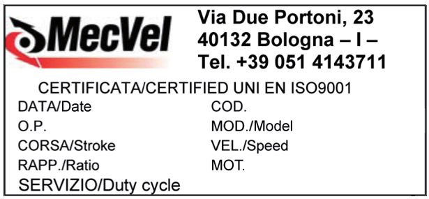
1 NORME E AVVERTENZE GENERALI........................................................................4
  1.1    Introduzione..............................................................................................4
  1.2    Riferimenti normativi................................................................................4

2 DESCRIZIONE DELL’ATTUATORE LINEARE E CARATTERISTICHE TECNICHE.......5

                                                                                                                                      ITALIANO
  2.1     Configurazioni della serie HRS.................................................................5
  2.2     Descrizione dei componenti e degli accessori.........................................5
  2.2.1   Motorizzazioni...........................................................................................7
  2.2.2   Controllo e regolazione della corsa dell’attuatore lineare.......................8
  2.2.2.1 Taratura dei dispositivi..............................................................................8
  2.2.2.2 Finecorsa induttivi.....................................................................................8
  2.2.2.3 Encoder.....................................................................................................9
  2.2.3   Attacchi e dispositivi di fissaggio...........................................................10
  2.2.4   Dispositivo di anti-rotazione...................................................................10
  2.2.5   Chiocciola di sicurezza............................................................................10

3 TRASPORTO E SMALTIMENTO..............................................................................10

4 INSTALLAZIONE.....................................................................................................11
  4.1     Piazzamento e operazioni di installazione..............................................11
  4.2     Collegamento elettrico...........................................................................12
  4.3     Predisposizioni a carico dell’utente........................................................12

5 FUNZIONAMENTO.................................................................................................12
  5.1    Uso previsto e condizioni di utilizzo.......................................................12
  5.2    Preparazione del ciclo di lavoro e di carico............................................14
  5.3    Rischi residui...........................................................................................14
  5.3.1  Volantino per manovra manuale.............................................................15

6 MANUTENZIONE DELL’ATTUATORE LINEARE.....................................................16
  6.1   Precauzioni e indicazioni comportamentali generali..............................16
  6.2   Operazioni di manutenzione dell’attuatore lineare................................17
  6.3   Riparazione dell’attuatore lineare...........................................................17
  6.4   Sostituzione dell’attuatore lineare..........................................................18

7 CONDIZIONI DI GARANZIA...................................................................................18

8 NOTE           ................................................................................................................18

                                                                           Manuale uso e manutenzione serie HRS - 3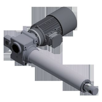
1 NORME E AVVERTENZE GENERALI
           1.1 INTRODUZIONE
           Il presente manuale è proprietà di MecVel.
           Tutti i diritti sono riservati, viene pertanto vietata la riproduzione o la cessione a terzi dei
           contenuti del presente documento.
ITALIANO

           MecVel si riserva il diritto di apportare modifiche al manuale senza uno specifico
           preavviso.
           Prima di procedere all’utilizzo dell’attuatore lineare si raccomanda di leggere
           attentamente questo documento.
           L’attuatore lineare non è e non deve essere considerato un dispositivo di sicurezza.
           L’utente finale, o il costruttore della macchina o dell’impianto all’interno del quale
           l’attuatore lineare è utilizzato come componente, è responsabile della sicurezza della
           macchina o dell’impianto, e quindi è tenuto a installare l’attuatore lineare conformemente
           alle norme di sicurezza applicabili vigenti nel Paese d’installazione e d’utilizzo.
           Il presente manuale riguarda gli attuatori lineari della serie HRS, descritti nelle successive
           sezioni.

           1.2 RIFERIMENTI NORMATIVI
           Le norme di sicurezza applicate dal fabbricante per la progettazione e la realizzazione
           dell’apparato in conformità alla Direttiva macchine 2006/42/CE sono riportate all’interno
           del fascicolo tecnico di proprietà di MecVel.
           NOTA: per ulteriori dettagli contattare MecVel.

           Ogni attuatore lineare è inoltre provvisto di un’etichetta o targa dati riportante le
           seguenti informazioni:
           • Dati del costruttore
           • Modello
           • Anno di fabbricazione
           Si riporta a titolo di esempio una delle etichette o targhe dati apposte da MecVel sul
           prodotto:

           4 - Manuale uso e manutenzione serie HRS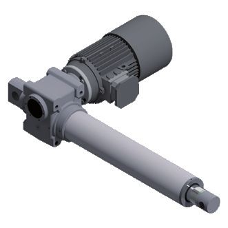
2 DESCRIZIONE DELL’ATTUATORE LINEARE E CARATTERISTICHE TECNICHE
2.1 CONFIGURAZIONI DELLA SERIE HRS
STELO/MADREVITE
MOTORE RIDUTTORE ASTA FINECORSA
MODELLO
CA (n. stadi) Ricircolo Chiocciola TRASLANTE FCI *1
Trapez.
ITALIANO
sfere di sicurezza
HRMS • 1 • • Cromata
HRMS-VRS • 1 • • Cromata
HRMS-FCI • 1 • • Cromata •
HRMS-VRS-FCI • 1 • • Cromata •
HRS 1 • • Cromata
HRS-VRS 1 • • Cromata
HRS-FCI 1 • • Cromata •
HRS-VRS-FCI 1 • • Cromata •
*1: FCI = finecorsa induttivo
Tutte le versioni degli attuatori lineari della serie HRS sono disponibili nelle taglie 50 (per
50 kN), 100 (per 100 kN) e 200 (per 200 kN).
I motori in CA possono essere equipaggiati con:
• Predisposizione inverter
• Freno elettromagnetico negativo (frenato se non alimentato elettricamente)
• Albero con doppia sporgenza (se non è presente il freno elettromagnetico negativo)
2.2 DESCRIZIONE DEI COMPONENTI E DEGLI ACCESSORI
Per le prestazioni, fare riferimento al catalogo del prodotto.
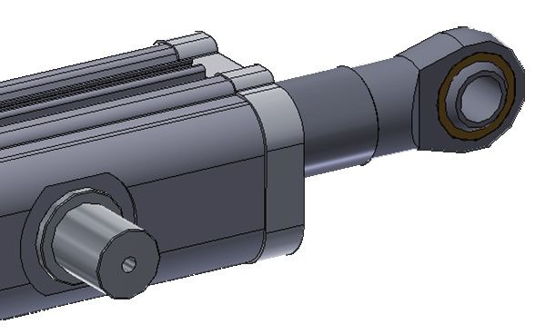
Dal disegno di seguito se ne identificano le parti principali.
Le configurazioni possibili sono riportate sopra.
2
1. Attacco posteriore 1 6
2. Riduttore
3. Cannotto
4. Attacco anteriore 3
5. Asta traslante 5
6. Motore elettrico
4
Manuale uso e manutenzione serie HRS - 5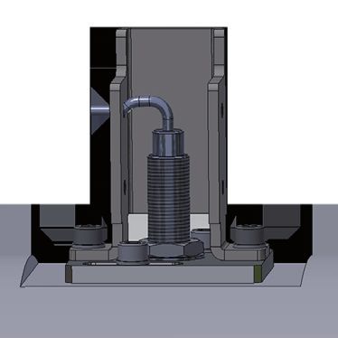
CARATTERISTICHE TECNICHE

                                                      Trifase 400-830 V/50 Hz
                                                      Trifase 390-830 V/60 Hz
ITALIANO

                                                      Monofase 190-400 V/50 Hz
            Motorizzazione CA
                                                      Monofase 220-480 V/60 Hz
                                                      Per tensioni differenti, fare riferimento ai
                                                      dati di targa sul motore

            Meccanismo di riduzione                   Vite senza fine/Ruota elicoidale

                                                      Stelo e madrevite con filetto trapezoidale o
            Meccanismo di traslazione
                                                      a ricircolo di sfere

            Asta traslante                            Cromata

                                                      Anteriori
            Attacchi
                                                      Posteriori
            Possibili dispositivi di controllo della Finecorsa
            corsa                                    Encoder
                                                      Riduttore: permanente a grasso o olio
            Lubrificazione
                                                      Asse di spinta: a grasso
                                                      Variabile in base alla configurazione (standard
            Grado di protezione
                                                      IP50, IP65 su richiesta)

                                                      Variabile in base alla configurazione, secondo
                                                      la formula approssimata:
                                                      HRS 50: 75 [kg] + 155 [kg/m] x corsa [m]
            Peso
                                                      HRS 100: 80 [kg] + 160 [kg/m] x corsa [m]
                                                      HRS 200: 150 [kg] + 180 [kg/m] x corsa [m]
                                                      Escluso il peso del motore

           6 - Manuale uso e manutenzione serie HRS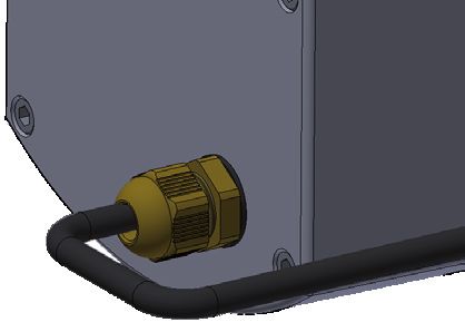
2.2.1 MOTORIZZAZIONI

                                        Monofase                        Trifase
  Variabili opzionali
   per motori in CA
                              Senza freno Con freno *1 Senza freno Con freno *1

                                                                                               ITALIANO
    Albero sporgente *2             •                              •

 Condensatore elettronico
                                    •               •
       di avvio *3

  Predisposizione inverter          •              • *4            •              • *4

*1: il freno negativo mantiene il motore frenato in assenza di alimentazione elettrica,
consente maggiore precisione e ripetibilità della posizione di arresto e rende
irreversibile il moto dell’attuatore lineare.
NB: nel caso di grandi masse inerziali, l’impiego del motore autofrenante può generare
sovraccarichi agli organi meccanici, rischiando di ridurre la vita dell’attuatore lineare.
Per applicazioni particolari, consultare l’ufficio tecnico di MecVel.
ATTENZIONE ai motori autofrenanti con leva di sblocco: attivando la leva di sblocco,
il moto dell’attuatore lineare potrebbe diventare reversibile. Nella progettazione
dell’applicazione, tenere in considerazione che i carichi sospesi e/o le forze assiali
possono provocare il movimento involontario dell’asta traslante.

*2: il motore con albero sporgente (dal lato opposto all’attuatore lineare) può essere
utile per manovre manuali e/o per l’applicazione di sensori di movimento.
NB: l’albero sporgente non ha nessuna protezione. Nella progettazione
dell’applicazione, occorre tenere in considerazione che le parti collegate all’albero
vengono poste in rotazione durante il funzionamento del motore.

*3: il condensatore elettrico di avvio facilita la partenza del motore con pieno carico.

*4: per motori autofrenanti comandati da inverter è necessario azionare il freno
separatamente dal motore.
NB: durante la progettazione dell’applicazione, occorre definire come gestire il
transitorio dato dalle rampe di accelerazione e decelerazione del motore.

                                                    Manuale uso e manutenzione serie HRS - 7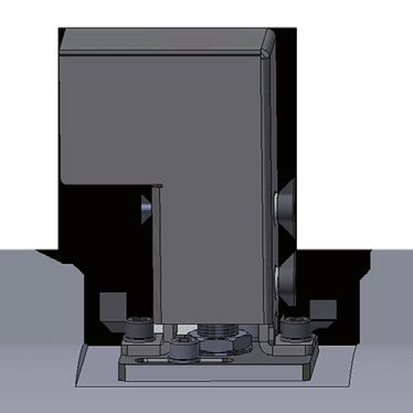
2.2.2 CONTROLLO E REGOLAZIONE DELLA CORSA DELL’ATTUATORE LINEARE
           Agli attuatori lineari si possono applicare diversi sistemi di controllo della corsa. Le
           tipologie di dispositivi disponibili in questo caso sono:
           • Finecorsa induttivi (FCI)
           • Encoder
ITALIANO

           2.2.2.1 TARATURA DEI DISPOSITIVI
           2.2.2.2 FINECORSA INDUTTIVI (FCI)
           La posizione dei finecorsa induttivi non è modificabile dall’utilizzatore.
           In fase d’ordine del prodotto, occorre specificare le quote relative agli interassi del
           martinetto “chiuso” e “aperto”.

                                      * il prodotto raffigurato è indicativo
                                                                                     NA + NC
                                                                               I
                                                                                                +   marrone
                                                                                                    nero
                                                                                                    bianco
                                                                                                    blu
                                                                                                –

                                    FCIC                       FCIA
                            finecorsa martinetto       finecorsa martinetto
                                tutto chiuso               tutto aperto

                               CARATTERISTICHE FINECORSA INDUTTIVI FCI
                 Tensione di alimentazione (UB)                                    5 ÷ 40 Vdc
                 Temperatura di funzionamento                                  -25°C ÷ +75°C
                            Protezione                                                IP67
                  Visualizzazione stato di uscita                                  LED giallo

           8 - Manuale uso e manutenzione serie HRS
Per registrare la posizione dei finecorsa FCI (se registrabili), utilizzare la seguente
procedura:
1. Rimuovere il coperchio di protezione B agendo sulle viti A
2. Allentare le viti C
3. Spostare il finecorsa D, posizionato sull’apposito piastrino, nella direzione desi-
ITALIANO
derata
4. Serrare le viti C
5. Riposizionare il coperchio di protezione B
6. Serrare le viti A
* immagine indicativa
B
A
C C
A
D
2.2.2.3 ENCODER
Encoder sui motori in CA:
• Encoder incrementale bidirezionale senza e con impulso di zero IP54 (stan-
dard)
• Impulsi/giro disponibili: 50/100/200/400/500/512/1000/1024 (standard)
• Circuiti d’uscita disponibili: Line Drive 5 Vdc (standard), Push Pull 20 Vdc, Open
Collector NPN 10-30 Vdc, Open Collector PNP 10-30 Vdc
Rosso ÷ Vdc
Nero 0 Vdc + Vdc + Vdc
Verde A Out
Giallo B Out Out
Blu Z
Marrone -A 0 Vdc 0 Vdc
Arancione -B
Bianco -Z LINE DRIVE PUSH-PULL
Manuale uso e manutenzione serie HRS - 92.2.3 ATTACCHI E DISPOSITIVI DI FISSAGGIO
Sono previsti attacchi standard e a disegno. Devono essere scelti in relazione
all’installazione dell’attuatore lineare, al fine di annullare l’eccentricità del carico. Si
sottolinea che sull’attacco si scarica la coppia di reazione che agisce sulla madrevite
in seguito all’applicazione del carico, perciò nel caso di attacchi a forcella o a snodo
ITALIANO
sferico si deve prevedere il dispositivo di anti-rotazione.
2.2.4 DISPOSITIVO DI ANTI-ROTAZIONE
Il dispositivo di anti-rotazione è necessario quando l’applicazione non permette di
vincolare l’asta traslante alle rotazioni attorno al proprio asse (obbligatorio con attacco
anteriore a snodo sferico o forcella).
2.2.5 CHIOCCIOLA DI SICUREZZA
La chiocciola di sicurezza è un dispositivo opzionale previsto per evitare l’eventuale
collasso dell’attuatore lineare causato dall’eccessiva usura della chiocciola su cui agisce
la vite trapezia. Carichi gravosi e uso prolungato potrebbero usurare la chiocciola
fino all’esaurimento della filettatura sulla vite trapezia. In questo caso interviene la
chiocciola di sicurezza, realizzata in acciaio, che prende il posto della chiocciola di
lavoro, impedendo che l’asta traslante si sfili dall’attuatore lineare o cada al suo interno.
L’intervento della chiocciola di sicurezza è identificabile tramite due fenomeni:
• Improvviso aumento della corrente assorbita dal motore, facilmente intercettabile
dall’intervento del salvamotore per i motori in CA
• Improvviso aumento della rumorosità, data dall’attrito radente (acciaio su acciaio)
tra vite trapezia e chiocciola di sicurezza
NB: la chiocciola di sicurezza non è prevista per le versioni VRS.
3 TRASPORTO E SMALTIMENTO
Il prodotto viene consegnato in imballi (scatole di cartone, casse di legno, ecc.) a
seconda degli accordi con il cliente e in base alle dimensioni del prodotto stesso. Si
raccomanda di movimentare i prodotti dopo aver aperto l’imballo, utilizzando idonei
sistemi di movimentazione quali carrelli elevatori, transpallet, cinghie di sicurezza. Si
richiama l’attenzione al rispetto delle condizioni di sicurezza per il trasporto del prodotto
da parte dell’operatore, in particolare si ricorda di indossare opportuni dispositivi
di protezione individuale. Prima della movimentazione dell’imballo contenente il
prodotto, si raccomanda di valutare la posizione approssimata del baricentro, mentre
durante la movimentazione si prega di porre la massima attenzione per evitare che
eventuali urti danneggino l’attuatore lineare. All’interno dell’attuatore lineare ci sono
componenti in acciaio, leghe di alluminio, tecnopolimeri, materiali sintetici, parti in
rame e lubrificanti: per il loro smaltimento si raccomanda la consegna a un’azienda
specializzata.
10 - Manuale uso e manutenzione serie HRS4 INSTALLAZIONE
4.1 PIAZZAMENTO E OPERAZIONI DI INSTALLAZIONE
L’attuatore lineare deve essere installato in modo che i carichi a esso applicati
risultino agire nella sola direzione assiale. Si fa divieto di applicare carichi torsionali
sull’asse longitudinale. In fase di montaggio, è necessario curare l’allineamento dei
ITALIANO
punti di fissaggio dell’attuatore lineare. A tal fine è opportuno indicare, in sede di
scelta dell’attuatore lineare, i fissaggi anteriori e posteriori adeguati alla situazione
di carico cui sarà sottoposto l’attuatore lineare, così da evitare disallineamenti che
causerebbero il funzionamento irregolare. Si raccomanda un’installazione robusta
e sicura, che garantisca la stabilità dell’attuatore lineare durante il funzionamento,
secondo le indicazioni elencate di seguito:
1. Disporre il foro dell’attacco posteriore dell’attuatore lineare in posizione coassiale
al foro del supporto esterno
2. Serrare in modo da rendere l’attuatore lineare stabile al supporto esterno
3. Collegare il carico all’attacco anteriore dell’attuatore lineare utilizzando opportuni
dispositivi di fissaggio (perni, viti, spine, ecc.)
4. Eseguire il collegamento elettrico
L’eccentricità del carico dovuta a una scelta errata dei fissaggi e/o da un
montaggio scorretto, con conseguente disallineamento dei punti di fissaggio,
dà origine a carichi radiali, con conseguente usura dei componenti interni
dell’attuatore lineare e irregolarità nel suo funzionamento.
è necessario che l’attuatore lineare lavori all’interno della sua corsa utile, evitando
l’arresto a battuta meccanica. L’arresto a battuta meccanica dovuto a un utilizzo
dell’attuatore lineare oltre i limiti della sua corsa utile causa il danneggiamento dei
componenti interni. A eccezione degli attuatori lineari muniti di finecorsa cablati con
diodi, prima di azionare il motore assicurarsi del corretto funzionamento dei dispositivi
di controllo della corsa. Il malfunzionamento degli stessi può provocare urti ai
componenti interni dell’attuatore lineare, con conseguenti ulteriori malfunzionamenti
e/o cedimenti strutturali. La prima volta che si avvia l’attuatore lineare si consiglia
di partire da una posizione intermedia della corsa, per verificare la correttezza della
direzione del movimento, evitando gli urti interni di cui sopra.
Per attuatori lineari senza dispositivo di anti-rotazione, evitare la rotazione
manuale dell’asta traslante. In caso contrario si rischia, al primo avvio, di
provocare urti ai componenti interni dell’attuatore lineare, con conseguenti
possibili cedimenti strutturali.
Per evitare un sovraccarico accidentale sull’attuatore lineare, si consiglia di installare
un limitatore di corrente che non intervenga durante la fase di spunto del motore e
sia tarato al 15% in più della corrente massima di esercizio.
Manuale uso e manutenzione serie HRS - 11Si ricorda di non mettere mai in funzione l’attuatore lineare senza prima aver
eseguito correttamente le operazioni di posizionamento sopra indicate.
4.2 COLLEGAMENTO ELETTRICO
Le operazioni di collegamento elettrico e taratura devono essere effettuate da
ITALIANO
personale esperto, istruito e informato.
4.3 PREDISPOSIZIONI A CARICO DELL’UTENTE
L’attuatore lineare deve essere messo in servizio all’interno di un contesto conforme
minimo alle seguenti Direttive comunitarie:
• 2006/42/CE: Direttiva macchine
• 2014/30/UE: Direttiva E.M.C.
5 FUNZIONAMENTO
L’attuatore lineare è destinato alla movimentazione di carichi. Tramite opportuni
meccanismi, il moto rotatorio del motore viene trasformato nel moto lineare dell’asta
traslante. Il carico, sempre e solo in direzione assiale, può essere applicato in tiro o in
spinta, indipendentemente dal verso di avanzamento dell’asta traslante.
5.1 USO PREVISTO E CONDIZIONI DI UTILIZZO
L’attuatore lineare è progettato per un utilizzo conforme alle condizioni specificate
da MecVel e riportate nel catalogo del prodotto. Per l’uso si richiama l’attenzione
al fattore di servizio dell’attuatore lineare e alle condizioni ambientali. Il fattore di
servizio e le condizioni ambientali sono parametri che si influenzano a vicenda. Il
fattore di servizio è definito come il rapporto percentuale tra il tempo di lavoro e il
tempo di sosta nel ciclo, calcolato su una base di tempo di max. 5 minuti.
% fattore di servizio = [tempo funzionamento/(tempo funzionamento + tempo sosta)] x 100
Le condizioni ambientali sono caratterizzate dalla temperatura e dagli elementi
che ne definiscono l’aggressività (umidità, salinità, polverosità, ecc.). Il fattore di
servizio standard cui sono riferite le prestazioni degli attuatori lineari è S3 30% a una
temperatura ambiente di riferimento di -10°C +60°C.
Non tutti gli attuatori lineari MecVel sono idonei ad essere installati in
ambienti con atmosfera potenzialmente esplosiva. In questo caso, contattare
MecVel.
12 - Manuale uso e manutenzione serie HRS* il prodotto raffigurato è indicativo
ITALIANO
SOLLECITAZIONI MASSIME
Grandezza AMMISSIBILI [N]
Dinamico Statico
HRS 50 50000 50000
HRS 100 100000 100000
HRS 200 200000 200000
* il prodotto raffigurato è indicativo
SOLLECITAZIONI MASSIME
Grandezza AMMISSIBILI [N]
Dinamico Statico
HRS 50 50000 Vedi tabelle seguenti
HRS 100 100000 Vedi tabelle seguenti
HRS 200 200000 Vedi tabelle seguenti
Vite
Grandezza
TPN VRS
HRS 50 Ø 40 Ø 50
HRS 100 Ø 55 Ø 63
HRS 200 Ø 70 Ø 80
Manuale uso e manutenzione serie HRS - 13Carico [daN]
Ø 80
ITALIANO
Ø 70
Ø 63
Ø 55
Ø 50
Ø 40
Lunghezza vite [m]
5.2 PREPARAZIONE DEL CICLO DI LAVORO E DI CARICO
Prima di poter iniziare il ciclo di lavoro bisogna verificare:
• La corretta installazione dell’attuatore lineare
• La corretta taratura degli eventuali dispositivi di controllo della corsa
• La corretta applicazione del carico di lavoro in relazione alle istruzioni fornite
5.3 RISCHI RESIDUI
Come previsto dalla Direttiva macchine 2006/42/CE, durante la progettazione è stata
effettuata la valutazione dei rischi da cui, data la natura propria dell’attuatore lineare,
emergono i seguenti rischi residui.
RISCHIO SEGNALETICA
APPARATO MISURE
RESIDUO LOCALE
• Manipolare dopo aver indossato
Ustione per Motore,
i guanti
temperatura asta traslante,
• Adottare opportune protezioni in
elevata riduttore
funzione del tipo di applicazione
• Caduta dell’attuatore lineare
Cedimento Attuatore
• Proiezione incontrollata delle parti
strutturale lineare
collegate all’attuatore lineare
Volantino
• Collegare il finecorsa di sicurezza MS
Urti e per manovra
• Adottare dispositivi di protezione
collisioni manuale (vedi
individuale
pag. seguente)
14 - Manuale uso e manutenzione serie HRSIn ogni modo è vietata la messa in servizio dell’attuatore lineare fino a quando
l’apparecchiatura finale a cui è destinato non è stata dichiarata conforme alle Direttive
comunitarie di riferimento.
5.3.1 VOLANTINO PER MANOVRA MANUALE
ITALIANO
Gli attuatori lineari possono essere dotati di volantino per le manovre manuali.
Il volantino può essere ubicato nella parte posteriore del motore o sulla cassa del
riduttore, in posizione laterale (vedi fig.). Il volantino è dotato d’impugnatura
reclinabile, innesto assiale e finecorsa di sicurezza. Per attivare la manovra manuale
occorre estrarre l’impugnatura *1 e spingere il volantino fino al completo ingranamento
dell’innesto. Il finecorsa di sicurezza MS intercetta il volantino nella posizione “inserito”
ed è predisposto per il collegamento al circuito elettrico di comando del motore.
Per evitare che il volantino ruoti insieme al motore, occorre collegare il finecorsa di
sicurezza MS al circuito elettrico di comando del motore. Il finecorsa di sicurezza MS
è dotato di contatto in scambio (NC + NO) idoneo a essere collegato con massimo
230 V/2 A. Si consiglia di utilizzare il contatto NC per interrompere il circuito del
servocomando del motore.
*1: questa manovra non è indispensabile, è anche possibile ruotare il volantino
impugnandolo sul bordo esterno e imprimendo un moto rotatorio
MS
MS MS
Volantino in posizione Volantino in posizione Volantino in posizione
laterale sinistra laterale destra posteriore al motore
Spingere per innestare il volantino in Tirare per disinnestare il volantino dalla
posizione di manovra manuale posizione di manovra manuale
Manuale uso e manutenzione serie HRS - 15Per i motori monofase, non collegare mai direttamente il finecorsa di sicurezza MS al
conduttore che alimenta il motore. Prima di mettere in servizio l’attuatore lineare, come
ITALIANO
previsto dalla Direttiva macchine 2006/42/CE, è indispensabile che venga eseguita la
corretta valutazione dei rischi e di conseguenza attivate le azioni necessarie. Se ne
riportano di seguito alcune d’esempio:
• Applicare i necessari dispositivi di protezione individuale (es. ripari mobili, ripari
interbloccati o altri dispositivi che impediscano il contatto accidentale con parti
mobili)
• Collocare in posizione ben visibile eventuali cartelli o segnali di allerta
• Collocare in posizione ben visibile una targhetta che evidenzi la relazione tra
il senso di rotazione del volantino e il verso di movimento dell’asta traslante
dell’attuatore lineare
• Collegare il finecorsa di sicurezza MS al circuito elettrico di comando del motore
• Corredare il manuale d’istruzioni della macchina finale in cui verrà utilizzato
l’attuatore lineare delle necessarie istruzioni e modalità d’intervento per la
manovra manuale di emergenza
6 MANUTENZIONE DELL’ATTUATORE LINEARE
Durante le operazioni di manutenzione è necessario prendere tutte le
precauzioni del caso per evitare situazioni di pericolo a carico dell’operatore.
Si raccomanda di leggere attentamente la presente sezione del manuale.
6.1 PRECAUZIONI E INDICAZIONI COMPORTAMENTALI GENERALI
Le operazioni di manutenzione dell’attuatore lineare devono essere eseguite da
personale esperto, istruito e informato. Gli operatori addetti alla manutenzione
devono essere dotati dei dispositivi di protezione individuale conformi all’ambiente
operativo. Prima di eseguire qualsiasi tipo di operazione indicata nel presente
manuale, è obbligatorio da parte dell’operatore indossare i dispositivi di protezione
individuale minimi di seguito indicati:
TUTA DA SCARPE GUANTI DA
LAVORO RINFORZATE LAVORO
16 - Manuale uso e manutenzione serie HRS6.2 OPERAZIONI DI MANUTENZIONE DELL’ATTUATORE LINEARE
Prima di qualsiasi intervento sull’attuatore lineare, verificare che la temperatura delle
superfici non sia tale da provocare danni, lesioni e ustioni all’operatore.
L’attuatore lineare richiede solo le seguenti operazioni di manutenzione periodica:
• Pulizia
ITALIANO
• Verifica di rumori anomali
• Verifica dello stato di conservazione delle superfici esterne, con particolare
riferimento agli organi mobili esterni
• Verifica dei sistemi di supporto e attacco ad altri organi:
* immagine indicativa
• Verifica del corretto passaggio dei cavi attraverso i pressacavi:
* immagine indicativa
6.3 RIPARAZIONE DELL’ATTUATORE LINEARE
In caso di anomalie non cercare di riparare autonomamente l’attuatore lineare, ma
contattare l’assistenza tecnica MecVel per ricevere le necessarie istruzioni.
Manuale uso e manutenzione serie HRS - 176.4 SOSTITUZIONE DELL’ATTUATORE LINEARE
L’eventualità di sostituire un attuatore lineare si presenta quando si verifica una rottura
del prodotto stesso, un suo malfunzionamento non compatibile con le condizioni
di uso, e in caso di rimozione dell’attuatore lineare per smantellamento completo
dell’attrezzatura o macchinario sul quale è montato.
ITALIANO
In questi casi è obbligatorio adottare le misure di sicurezza già descritte nel presente
manuale per quanto riguarda le operazioni di manutenzione.
Per gli attuatori lineari che presentano anomalie di funzionamento o di controllo,
contattare l’assistenza tecnica MecVel per ricevere procedure, istruzioni e autorizzazioni
necessarie per la sostituzione o la riparazione.
NOTA: nel caso si contatti l’assistenza tecnica MecVel, fare sempre riferimento al
numero OP indicato sull’etichetta dell’attuatore lineare:
7 CONDIZIONI DI GARANZIA
Per le condizioni generali di vendita e di garanzia, consultare il catalogo MecVel o il
sito www.mecvel.it.
8 NOTE
Note particolari per l’uso e la manutenzione di questo modello di attuatore lineare
sono disponibili solo in caso di configurazioni particolari.
18 - Manuale uso e manutenzione serie HRSHRS
ENGLISH
Use and maintenance handbook HRS - 191 GENERAL RULES AND WARNINGS...................................................................21
1.1 Introduction............................................................................................21
1.2 Regulatory references.............................................................................21
2 LINEAR ACTUATOR DESCRIPTION AND TECHNICAL SPECIFICATIONS........22
2.1 Configurations of HRS series..................................................................22
2.2 Description of components and accessories..........................................22
2.2.1 Motorizations..........................................................................................24
2.2.2 Control and adjustment of the linear actuator stroke............................25
2.2.2.1 Devices setup.........................................................................................25
2.2.2.2 Inductive limit switches...........................................................................25
2.2.2.3 Encoder...................................................................................................26
2.2.3 End-fittings.............................................................................................27
2.2.4 Anti-rotation device................................................................................27
2.2.5 Safety nut................................................................................................27
3 TRANSPORT AND DISPOSAL............................................................................27
4 INSTALLATION....................................................................................................28
4.1 Positioning and installation operations..................................................28
4.2 Electrical connection...............................................................................29
4.3 Duties of the user...................................................................................29
5 OPERATION........................................................................................................29
5.1 Intended use and conditions of use.......................................................29
5.2 Preparation of working and duty cycles.................................................31
5.3 Residual risks..........................................................................................31
5.3.1 Handwheel for manual driving...............................................................32
6 LINEAR ACTUATOR MAINTENANCE................................................................33
6.1 General precautions and behavioural guidelines...................................33
6.2 Linear actuator maintenance operations................................................34
6.3 Repairing the linear actuator..................................................................34
ENGLISH
6.4 Replacing the linear actuator..................................................................35
7 WARRANTY CONDITIONS.................................................................................35
8 NOTES ................................................................................................................35
20 - Use and maintenance handbook HRS1 GENERAL RULES AND WARNINGS
1.1 INTRODUCTION
This handbook is the property of MecVel.
All rights are reserved.
The contents of this document may not be reproduced or transferred to third
parties.
MecVel reserves the right to make changes to this handbook without specific notice.
Read this document carefully before using the linear actuator.
The linear actuator is not and must not be considered as a safety device.
The end-user or the manufacturer of the machine or system in which the linear actuator
is used as a component is responsible for the safety of the machine or system and
is therefore obliged to install the linear actuator in accordance with the applicable
safety regulations of the country of installation and use.
This handbook regards the linear actuators of the HRS series, which are described in
the following sections.
1.2 REGULATORY REFERENCES
The safety standards applied by the manufacturer for the design and manufacture of
the device in accordance with the Machinery Directive 2006/42/EC are given in the
technical file, which is the property of MecVel.
NOTE: contact MecVel for further details.
Each linear actuator is also provided with a label or nameplate with the following
information:
• Manufacturer’s data
• Model
• Year of manufacture
The following is an example of one of the labels or nameplates fitted by MecVel on
the product: ENGLISH
Use and maintenance handbook HRS - 212 LINEAR ACTUATOR DESCRIPTION AND TECHNICAL SPECIFICATIONS
2.1 CONFIGURATIONS OF HRS SERIES
LEAD SCREW/NUT LIMIT
AC GEAR BOX
MODEL PUSH ROD SWITCHES
MOTOR (no. stages)
ACME Ballscrew Safety nut FCI *1
HRMS • 1 • • Chromed
HRMS-VRS • 1 • • Chromed
HRMS-FCI • 1 • • Chromed •
HRMS-VRS-FCI • 1 • • Chromed •
HRS 1 • • Chromed
HRS-VRS 1 • • Chromed
HRS-FCI 1 • • Chromed •
HRS-VRS-FCI 1 • • Chromed •
*1: FCI = inductive limit switches
All versions of linear actuators from HRS series are available in the following sizes: 50 (for
up to 50 kN), 100 (for up to 100 kN) and 200 (for up to 200 kN).
AC motors can be equipped with:
• Inverter predisposition
• Negative electromagnetic brake (braked if not electrically powered)
• 2’ shaft (if there is no negative electromagnetic brake)
2.2 DESCRIPTION OF COMPONENTS AND ACCESSORIES
For performance, refer to the product catalog.
The following drawing identifies its main parts.
Possible configurations are listed above
2
ENGLISH
1. Rear end 1 6
2. Gear box
3. Cover tube
4. Front end 3
5. Push rod 5
6. Electric motor
4
22 - Use and maintenance handbook HRSTECHNICAL SPECIFICATIONS
Three-phase 400-830 V/50 Hz
Three-phase 390-830 V/60 Hz
Single-phase 190-400 V/50 Hz
AC motor
Single-phase 220-480 V/60 Hz
For different voltages, refer to the data on
the motor plate
Gear reduction mechanism Worm screw/Worm wheel
Linear movement mechanism ACME or ballscrew lead screw and nut
Push rod Chromed
Front
Ends
Rear
Limit switches
Possible stroke control devices
Encoder
Gear box: permanent grease or oil
Lubrication
Push rod: grease
Variable depending on configuration (IP50
Protection class
standard, IP65 on request)
Variable depending on the configuration,
according to the approximate formula:
HRS 50: 75 [kg] + 155 [kg/m] x stroke [m]
Weight
HRS 100: 80 [kg] + 160 [kg/m] x stroke [m]
HRS 200: 150 [kg] + 180 [kg/m] x stroke [m]
Motor weight excluded
ENGLISH
Use and maintenance handbook HRS - 232.2.1 MOTORIZATIONS
Single-phase Three-phase
Optional variables
for AC motors Without With Without With
brake brake *1 brake brake *1
2’ shaft *2 • •
Electronic start-up
• •
capacitor *3
Inverter predisposition • • *4 • • *4
*1: the negative brake keeps the motor braked in the absence of power supply, allows
greater precision and repeatability of the stop position and makes the linear actuator
motion irreversible.
NB: in case of large inertial masses, the use of the self-braking motor can generate
overloads on the mechanical parts, which may reduce the life of the linear actuator.
For special applications, contact MecVel’s technical department.
ATTENTION to self-braking motors with release lever: using the release lever, the
linear actuator motion may become reversible. While designing the application, keep
into consideration that hanged loads and/or axial forces could cause an involuntary
movement of the push rod.
*2: the motor with a 2’ shaft (on the opposite side of the linear actuator) can be useful
for manual operations and/or the application of motion sensors.
NB: the 2’ shaft has no protection. When designing the application, it must be taken
into consideration that the parts connected to the shaft are rotated during motor
operation.
ENGLISH
*3: the electric start-up capacitor facilitates starting the motor with a full load.
*4: for inverter-controlled brake motors, the brake must be applied separately from
the motor.
NB: when designing the application, it is necessary to define how to handle the
transient given by the motor’s acceleration and deceleration ramps.
24 - Use and maintenance handbook HRS2.2.2 CONTROL AND ADJUSTMENT OF THE LINEAR ACTUATOR STROKE
Different stroke control systems can be applied to linear actuators. In this case, the
types of devices available are:
• Inductive limit switches (FCI)
• Encoder
2.2.2.1 DEVICES SETUP
2.2.2.2 INDUCTIVE LIMIT SWITCHES (FCI)
The position of these limit switches cannot be adjusted by the user.
While ordering the product, values related to “all-closed” and “all-opened” linear
actuator positions must be defined.
* product shown as example
NA + NC
I
+ brown
black
white
blue
–
FCIC FCIA
closing inductive opening inductive
limit switch limit switch
INDUCTIVE LIMIT SWITCHES FEATURES
Supply voltage (UB) 5 ÷ 40 Vdc
Working temperature range -25°C ÷ +75°C
Protection IP67
Switch status indicator Yellow LED
ENGLISH
Use and maintenance handbook HRS - 25To regulate the FCI limit switches position (if adjustable), proceed as follows:
1. Remove the 2 screws “A”
2. Lift the cover “B”
3. Loosen the 2 screws “C”
4. Slide the plate “D” in the two directions until it reaches the desired position
5. Tighten the 2 screws “C”
6. Put the cover “B”
7. Lock with the 2 screws “A”
* illustrative image
B
A
C C
A
D
2.2.2.3 ENCODER
Encoder on AC motors:
• Bi-directional incremental encoder without and with zero pulse IP54 (standard)
• Available pulses/revolution: 50/100/200/400/500/512/1000/1024 (standard)
• Available output circuits: Line Drive 5 Vdc (standard), Push Pull 20 Vdc, Open
Collector NPN 10-30 Vdc, Open Collector PNP 10-30 Vdc
Red ÷ Vdc
+ Vdc + Vdc
ENGLISH
Black 0 Vdc
Green A Out
Yellow B Out Out
Blue Z
Brown -A 0 Vdc 0 Vdc
Orange -B
White -Z LINE DRIVE PUSH-PULL
26 - Use and maintenance handbook HRS2.2.3 End-fittings
Standard and customised end-fittings are available. They must be chosen in relation
to the linear actuator installation, in order to cancel the load eccentricity. The end is
discharged by the reaction torque acting on the nut following the application of the
load, therefore the anti-rotation device must be provided in case of clevis or ball joint
ends.
2.2.4 ANTI-ROTATION DEVICE
The anti-rotation device is required when the application does not allow the push rod
to be constrained to rotate around its own axis (compulsory with clevis or ball joint
front ends).
2.2.5 SAFETY NUT
The safety nut is an optional device designed to avoid the possible collapse of the
linear actuator due to an excessive wear of the nut on which the lead screw acts.
Heavy loads and prolonged use could wear the nut until the end of the thread on
the lead screw. In this case, the safety nut, made of steel, acts taking the place of
the working nut and avoiding the push rod from slipping off or falling into the linear
actuator. The intervention of the safety nut can be identified by two cases:
• Sudden increase in the current absorbed by the motor, easily visible by the
intervention of the motor protector for AC motors
• Sudden increase in noise, due to the sliding between lead screw and safety nut
(steel on steel)
NB: the safety nut is not available with ballscrew versions.
3 TRANSPORT AND DISPOSAL
The product is delivered in packaging (cardboard boxes, wooden crates, etc.)
depending on the agreement with the customer and on the size of the product itself.
After unpacking, it is recommended to handle the product using suitable handling
systems such as forklifts, transpallets, safety belts. It is important that the operator
complies with the safety conditions for transporting the product, in particular by
wearing appropriate personal protective equipment. Before handling the package
containing the product, it is recommended to evaluate the approximate position of
ENGLISH
the centre of gravity while, during the handling, take great care to prevent any impact
from damaging the linear actuator. Inside the linear actuator, there are components
made of steel, aluminium alloys, technopolymers, synthetic materials, copper parts and
lubricants: for their disposal, it is recommended handing them over to a specialized
company.
Use and maintenance handbook HRS - 274 INSTALLATION
4.1 POSITIONING AND INSTALLATION OPERATIONS
The linear actuator must be installed in such a way that the loads applied to it act in
the axial direction only. It is forbidden to apply torsional loads on the longitudinal axis.
During assembly, care must be taken to align the fixing points of the linear actuator.
When selecting the linear actuator, it is advisable to specify front and rear ends that
are suitable for the load situation to which the linear actuator will be subjected, in
order to avoid misalignments that would cause irregular operation. A strong and
safe installation is recommended, ensuring the stability of the linear actuator during
operation, according to the following guidelines:
1. Arrange the hole of the linear actuator rear end coaxially with the hole of the
outer bracket
2. Tighten so that the linear actuator is stable on the outer support
3. Connect the load to the linear actuator front end using suitable fasteners (pins,
screws, etc.)
4. Proceed with the electrical connection
The load eccentricity due to incorrect choice of ends and/or incorrect
mounting, resulting in misalignment of the fastening points, gives rise to
radial loads, resulting in wear of the internal components of the linear
actuator and irregularities in its operation.
The linear actuator must work within its nominal stroke, in order to avoid a mechanical
stop. A mechanical stop due to use of the linear actuator beyond the limits of its
stroke causes damage to the internal components. With the exception of linear
actuators equipped with diode-wired limit switches, ensure that the stroke control
devices are functioning properly before operating the motor. Their malfunctioning
can cause the impact of the internal components of the linear actuator, resulting in
further malfunctions and/or structural failures. The first time the linear actuator is
started up, it is advisable to start from an intermediate position of the stroke, in order
to check that the direction of movement is correct and to avoid the internal impacts
mentioned above.
ENGLISH
For linear actuators without the anti-rotation device, avoid the manual
rotation of the push rod. Failure to do so may result in internal components
of the linear actuator being knocked out of alignment the first time it is
started up, leading to possible structural failures.
In order to avoid an unintentional overload on the linear actuator, it is recommended
to install a current limiter that does not intervene during the motor inrush phase and
set at 15% above the maximum operating current.
28 - Use and maintenance handbook HRSNever operate the linear actuator without first performing correctly the
positioning steps mentioned above.
4.2 ELECTRICAL CONNECTION
Electrical connection and calibration must be carried out by experienced, trained and
informed personnel.
4.3 DUTIES OF THE USER
The linear actuator must be commissioned within an environment that complies at
least with the following EU Directives:
• 2006/42/EC: Machinery Directive
• 2014/30/EU: E.M.C. Directive
5 OPERATION
The linear actuator is intended for handling loads. By means of appropriate mechanisms,
the rotatory motion of the motor is transformed into the linear motion of the push
rod. The load, always and only in the axial direction, can be applied in pull or push,
regardless of the direction of movement of the push rod.
5.1 INTENDED USE AND CONDITIONS OF USE
The linear actuator is designed for use in accordance with the conditions specified
by MecVel and listed in the product catalog. For use, attention is drawn to the duty
cycle of the linear actuator and the environmental conditions. The duty cycke and the
environmental conditions are parameters that influence each other. The duty cycle is
defined as the percentage ratio between the operating time and the rest time in the
cycle, calculated on a time basis of max. 5 minutes.
% duty cycle = [operating time/(operating time + rest time)] x 100
The environmental conditions are characterised by temperature and elements that
define their aggressiveness (humidity, salinity, dustiness, etc.). The standard duty cycle
to which the performance of linear actuators is referred is S3 30% at an environmental
reference temperature of -10°C +60°C.
ENGLISH
Not all MecVel linear actuators are suitable for installation in environments
with a potentially explosive atmosphere. In this case, contact MecVel.
Use and maintenance handbook HRS - 29* product shown as example
PERMISSIBLE STRESSES [N]
Size
Dynamic Static
HRS 50 50000 50000
HRS 100 100000 100000
HRS 200 200000 200000
* product shown as example
PERMISSIBLE STRESSES [N]
Size
Dynamic Static
HRS 50 50000 See following tables
HRS 100 100000 See following tables
HRS 200 200000 See following tables
ENGLISH
Screw
Size
ACME Ballscrew
HRS 50 Ø 40 Ø 50
HRS 100 Ø 55 Ø 63
HRS 200 Ø 70 Ø 80
30 - Use and maintenance handbook HRSLoad [daN]
Ø 80
Ø 70
Ø 63
Ø 55
Ø 50
Ø 40
Screw length [m]
5.2 Preparation of working and duty cycles
Before starting the duty cycle, it is necessary to check:
• The correct installation of the linear actuator
• The correct calibration of any stroke control device
• The correct application of the load according to the instructions given
5.3 RESIDUAL RISKS
As required by the Machinery Directive 2006/42/EC, a risk assessment was carried
out during the design phase, from which the following residual risks arise, due to the
nature of the linear actuator.
RESIDUAL LOCAL
PART PROCEDURE
RISK SIGNAL
• Handle after wearing gloves
High Motor, push
• Use appropriate protections
temperature rod,
depending on the type of
burns gear box
application
ENGLISH
• Fall of the linear actuator
Structural
Linear actuator • Uncontrolled projection of parts
failure
connected to the linear actuator
Handwheel for • Connect the safety limit switch
Bumps and
manual driving • Use personal protective
collisions
(see next page) equipment
Use and maintenance handbook HRS - 31In any case, it is forbidden to start the linear actuator until the machine for which it is
intended has been declared in compliance with the relevant EU Directives.
5.3.1 HANDWHEEL FOR MANUAL DRIVING
Linear actuators can be equipped with a handwheel for manual operations. The
handwheel can be placed at the rear of the motor or on the gear box housing, sideways
(see below). The handwheel is equipped with reclining handle, axial coupling and
safety limit switch. To activate the manual driving it is necessary to extract the handle
*1 and push the handwheel until the coupling is fully engaged. The MS safety limit
switch chatches the handwheel when it is in the “inserted” position and is designed for
the connection to the motor control circuit. To prevent the handwheel from rotating
together with the motor, the safety limit switch MS must be connected to the motor
control circuit. The MS safety limit switch is equipped with a changeover contact (NC
+ NO) suitable for connections with maximum 230 V/2 A. It is recommended to use
the NC contact to stop the motor control circuit.
*1: this operation is not mandatory, it is also possible to rotate the handwheel by the
outer edge and performing a rotary motion
MS
ENGLISH
MS MS
Handwhhel Handwheel Handwheel at the
on the left on the right rear of the motor
Push to engage the handwheel in Pull to disconnect the handwheel from
manual driving position the manual driving position
32 - Use and maintenance handbook HRSFor single-phase motors, never connect the MS safety limit switch directly to the
motor conductor.
Before to run the linear actuator, as required by the Machinery Directive 2006/42/EC,
it is mandatory that the correct risk assessment is carried out and all the necessary
actions performed.
Here some examples:
• Apply all the necessary personal protective equipment (as mobile barriers,
interlocked barriers or other devices able to avoid the accidental contact with
moving parts)
• Place warning signs in a clearly visible position
• Place a plate reporting the relation between the rotation direction of the handwheel
and the direction of the linear actuator push rod in a clearly visible position
• Connect the MS safety limit switch to the motor control circuit
• Add to the handbook of the whole machiney that will host the linear actuator all
the necessary instructions and possible operations regarding the manual driving
6 LINEAR ACTUATOR MAINTENANCE
During maintenance operations, all precautions must be taken to avoid
dangerous situations for the operator.
Read this section of the handbook carefully.
6.1 GENERAL PRECAUTIONS AND BEHAVIOURAL GUIDELINES
Maintenance operations on the linear actuator must be carried out by experienced,
trained and informed personnel.
Operators in charge for maintenance must be equipped with personal protective
equipment in compliance with the working environment.
Before carrying out any of the operations indicated in this handbook, the operator
must wear the minimum personal protective equipment indicated below:
ENGLISH
WORKING SAFETY SAFETY
OVERALLS SHOES GLOVES
Use and maintenance handbook HRS - 336.2 LINEAR ACTUATOR MAINTENANCE OPERATIONS
Before performing any operation on the linear actuator, check that the temperature of
the surfaces is not such that it could cause damage, injury or burns to the operator.
The linear actuator only requires the following periodic maintenance:
• Cleaning
• Checking for anomalous noises
• Checking the state of preservation of external surfaces, with particular reference
to external moving parts
• Checking of support systems and attachments to other parts:
* illustrative image
• Checking the correct passage of cables through cable glands
* illustrative image
ENGLISH
6.3 REPAIRING THE LINEAR ACTUATOR
In the event of faults, do not attempt to repair the linear actuator yourself, but contact
MecVel technical support for the necessary instructions.
34 - Use and maintenance handbook HRS6.4 REPLACING THE LINEAR ACTUATOR
The eventuality of replacing a linear actuator arises when the product itself breaks
down, when it malfunctions in a way that is not compatible with the conditions of
use, and when the linear actuator is removed due to the complete dismantling of the
machine on which it is mounted.
In these cases, it is mandatory to adopt the safety measures already described in this
handbook regarding maintenance operations.
For linear actuators with malfunctions or control faults, contact MecVel technical
support for procedures, instructions and approvals for replacement or repair.
NOTE: when contacting MecVel technical support, always refer to the OP number
indicated on the label or the nameplate of the linear actuator:
7 WARRANTY CONDITIONS
For general sale and warranty conditions, refer to MecVel catalog or to www.mecvel.com.
8 NOTES
Special notes on use and maintenance of this model of linear actuator are available only
for special configurations.
ENGLISH
Use and maintenance handbook HRS - 35MecVel Srl
Via Due Portoni, 23
40132 Bologna - Italy
E = m(e)c(vel)2
T. +39 051 4143711 The formula to automate your
info@mecvel.com linear motion with the best energy
www.mecvel.comPuoi anche leggere