Sea-Connect Wideband 3G/4G/LTE Antenna - ENG IT - Marine Products
←
→
Trascrizione del contenuto della pagina
Se il tuo browser non visualizza correttamente la pagina, ti preghiamo di leggere il contenuto della pagina quaggiù
Sea-Connect
      Wideband 3G/4G/LTE Antenna

ENG   Installation and user instructions
IT    Guida d’installazione e istruzioni utente

            www.scoutantenne.com                  rev. 12/2016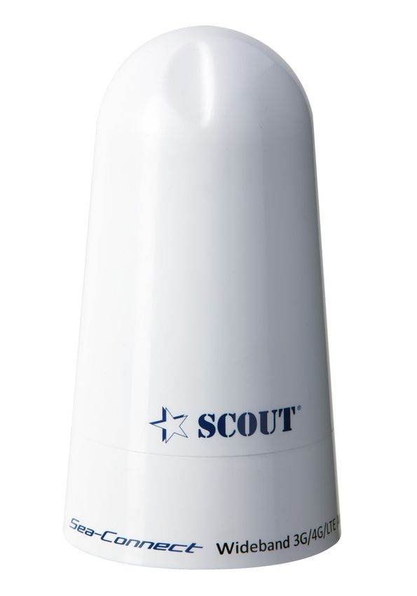
Introduction - Introduzione
Sea-Connect is a wideband antenna that provides coverage for 3G/4G/LTE and WLAN systems in a
compact and waterproof design, ideal for any type of boat. Excellent performance with VSWR less
than 1.5:1 in all 3G and 4G bands. The frequencies supported are 698-2700 MHz covering all major
ENG bands: 4G, 3G, AWS, LTE, CLR, DCS, IMT, ISM, PCS, WCDMA, WCS, WiFi, WiMax, Cellular.
Easy to install both on standard 1” x 14 threaded mounts and on deck as a permanent, through-
hole mount solution. The UV stable casing provides outstanding corrosion resistance in the
harshest environments. The antenna terminates in an N type female connector.
La nuova antenna multibanda Sea-Connect garantisce una eccellente copertura per 3G/4G/LTE
e per sistemi WLAN, il tutto incluso in un design compatto e waterproof ideale per ogni tipo di
imbarcazione. Le prestazioni eccellenti sono confermate da valori VSWR inferiori a 1.5:1 per le
bande 3G e 4G. Grazie a una copertura di banda completa da 698-2700 MHz l’antenna Sea-Connect
è perfettamente adatta a tutte le seguenti applicazioni: 4G, 3G, AWS, LTE, CLR, DCS, IMT, ISM, PCS,
ITA
WCDMA, WCS, WiFi, WiMax, Cellular.
L’antenna può essere installata sia su base standard con attacco 1” x 14 sia direttamente su deck
in modo stabile con foro per cavo passante.
L’involucro è resistente a raggi UV per prevenire il deterioramento del colore e resistente
all’ambiente marino. L’antenna termina con un connettore di tipo N femmina.
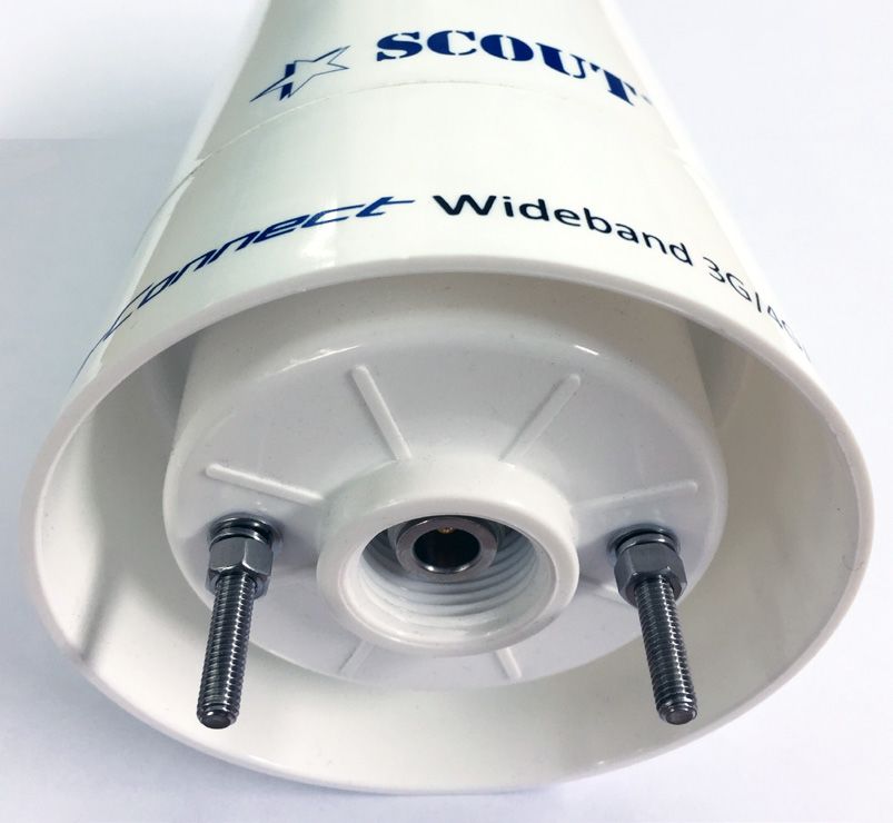
Contents - Contenuto
A - Antenna
B - Screw (2 pcs)
C - Washer (4 pcs) A
D - Grower washer (2 pcs)
E - Nut (4 pcs)
C
B
D
E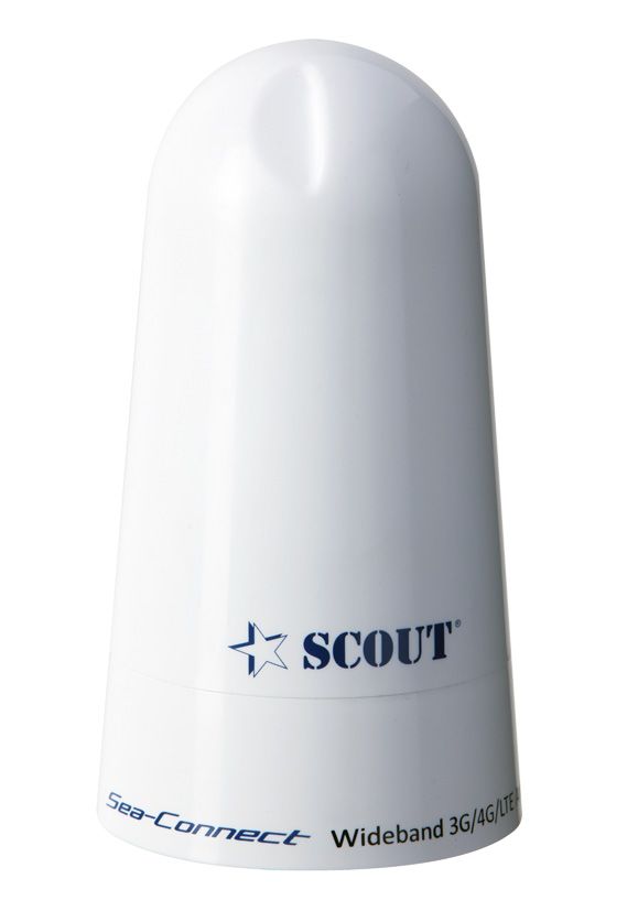
Antenna installation - Installazione dell’antenna

      Install the antenna in accordance with the following procedures to insure maximum performance
      of the antenna.
      ► The antenna should be installed in the place where is an all round clear view of the horizon and
ENG   as high as possible.
      ► Please keep clear the antenna from any obstacles.
      ► Use only high quality low-loss coaxial cable to reduce signal attenuation caused by the cable.
      Cable type LMR-400 is highly recommended.

      L’installazione dell’antenna deve procedere seguendo le presenti istruzioni per assicurarne la
      massima performance.
      ► Installare l’antenna in una posizione con visuale totalmente aperta dell’orizzonte e il più in alto
      possibile.
ITA
      ► Mantenere la visuale dell’antenna libera da ostacoli.
      ► Utilizzare unicamente cavi coassiali di elevata qualità a bassa perdita di segnale per evitare
      attenuazioni che possano compromettere il funzionamento dell’antenna. È consigliato l’utilizzo del
      cavo tipo LMR-400 per le sue proprietà conduttive anche ad elevate frequenze di funzionamento.

Installation type 1 - through-hole deck mounting
Installazione tipo 1 - montaggio su superficie piana

                                                                             Use the mounting template (that you’ll find in
                                                                         ENG the last page of this guide) to drill the three holes
                                                                             on the flat surface where it must be mounted.
           Drill hole,                                     Drill hole,
         5 mm (0.2 in)                                   5 mm (0.2 in)
           diameter                                        diameter

                                                                               Utilizzate la dima di montaggio (mounting
                                                                               template) che trovate nell’ultima pagina di questa
                                                                         ITA
                                                                               guida per operare i tre fori sulla superficie piana
                                                                               sulla quale volete installare l’antenna.

                                                Drill hole,
                                             12 mm (0.47 in)
                                                diameter
                                           (considering cable
                                             type LMR-400)

                     53 mm (2.1 in) bolt circle diameter

                         106 mm (4.1 in) complete unit
Run the coax cable through the central hole and fit the N male connector on the termination
ENG
that goes to the antenna.
Fate scorrere il cavo coassiale attraverso il foro centrale e montate il connettore N maschio sulla
ITA
estremità da colegare all’antenna.
Tighten the screws for approx 1 cm, then insert the washers, the grower washers and the nuts.
ENG
Then tighten the nuts.
Avvitate le viti nei due fori di montaggio presenti nel basamento dell’antenna, avvitandoli per
ITA
circa 1 cm. Poi inserite le rondelle, le rondelle grower e i dadi di bloccaggio. Quindi serrate i dadi.Connect the N male that you fitted on the termination
of the coax cable to the N female on the bottom of the
ENG
antenna, then set the antenna on the surface in a way that
both screws enter into the holes that you drilled earlier.
Avvitate il connettore N maschio presente all’estremità del
cavo al connettore N femmina presente nel basamento
ITA dell’antenna, quindi posizionate l’antenna sulla superficie
in modo che le viti entrino nei due fori creati in precedenza.
Insert the washers and the nuts and secure
ENG the antenna on the surface. The installation
is now complete.
Inserite le rondelle e i dadi per fissare l’antenna
ITA sul piano di montaggio. L’installazione è
completata.
Installation type 2 - mounting on a mount 1” x 14 thread
Installazione tipo 2 - montaggio su base 1” x 14 filetti
Connect the N male that you fitted on the termination
of the coax cable to the N female on the bottom of the
ENG
antenna, then set the antenna on the mount by screwing it.
The installation is now complete.
Avvitate il connettore N maschio presente all’estremità del
cavo al connettore N femmina presente nel basamento
ITA dell’antenna, quindi posizionate l’antenna sulla base
avvitandola. L’installazione è completata.Technical specifications - Specifiche tecniche
Polarization Vertical
Frequency Range 698-2700 MHz
VSWR ≤1. 5
Polarization Vertical
Input Impedance 50 ohm
Gain 4 dBi
Horizontal Beamwidth 360°
Vertical Beamwidth 60°
Max power 100W
Antenna diameter 11 cm (4”)
Antenna height 20 cm (8”)
Connector N female
Radome Material UV resistant ASA
Rated Wind Velocity 210 km/h
Operating temperature -40°C to +65°C
Support, Terms & Conditions - Supporto
► Sea-Connect is guaranteed against defective parts or workmanship for 2 years from time of
purchase. This excludes any malfunction caused by improper use, accidental or malicious damage.
This doesn’t affect your statutory rights.
► If you do experience a problem with the product contact Scout Customer Services on +39 059
ENG 566650.
► All instructions and models are subject to change without prior notice.
► Please keep these instructions safe for future reference.
► Recycle packaging where facilities exist.
► Sea-Connect è garantita per 2 anni da difetti di fabbricazione in termini di materiale e lavorazione
dal momento dell’acquisto. La garanzia esclude ogni malfunzionamento derivante da uso improprio
o accidentale dell’oggetto.
► In caso di problema tecnico potete contattate il servizio clienti di Scout al numero +39 059 566650.
ITA
► Le specifiche tecniche qui contenute possono variare a discrezione del produttore.
► Conservare le presenti istruzioni per consultazioni future.
► A fine vita non gettare questo apparecchio nella normale raccolta dei rifiuti, ma portalo presso dei
punti di raccolta autorizzati. In questo modo contribuirai a preservare l’ambiente.SEA-CONNECT MOUNTING TEMPLATE
rev. 12/2016
Drill hole, Drill hole,
5 mm (0.2 in) 5 mm (0.2 in)
diameter diameter
Drill hole,
12 mm (0.47 in)
diameter
(considering cable
type LMR-400)
53 mm (2.1 in) bolt circle diameter
106 mm (4.1 in) complete unitCONNECTIONS & FEATURES FAULT FINDING
No picture on TV
A: Wall fixing hole
■ Check amplifier LED is on
B: On/off power switch
NNECTIONS & FEATURES
C: LED power indicator
FAULT
■ Check coaxial cable connections FINDING
C ■ Adjust gain of amplifier
D: Gain control knob No picture on TV
■ TV or set top box not tuned in
A: E: hole
Wall fixing 12/24V power input
A ■ Poor LED
■ Check amplifier reception
is on area
B: On/off F: Antenna
power switch input
■ Check coaxial cable connections
D C: LED powerG: TV/Radio
indicator output
C ■ Adjust gain of amplifier
Picture breaks up or freezes
D: H : TV/Radio
Gain control knob output
■ TV or set top box not tuned in
E: 12/24V power input ■ Adjust gain of amplifier
A ■ Poor reception area
F: Antenna input ■ Poor reception
D G: TV/Radio output
H: TV/Radio output Picture breaks
PowerupLED
or freezes
does not illuminate when power is switched on
■ Adjust gain
■ Noofpower,
amplifier
check other devices on same electrical circuit
■ Poor reception
■ Fuse has blown
Power LED does not illuminate when power is switched on
■ No power, check other devices on same electrical circuit
F G H
■ Fuse has blown
2 YEAR GUARANTEE
G H This signal booster is guaranteed against defective parts or
workmanship for 2 years from time of purchase. This excludes any
malfunction caused be improper use, accidental or malicious
damage or removal of 2 theYEAR GUARANTEE
outer casing. This does not affect your
statutory rights.
This signal booster is guaranteed against defective parts or
workmanship for 2 years from time of purchase. This excludes any
malfunction caused be improper use, accidental or malicious
damage or removal of the outer casing. This does not affect your
statutory rights.
SPECIFICATIONS PACK CONTENTS
A
2A F type 1 1/ 4” x dia 1/ 4”
): 40-860
2-69 SPECIFICATIONS Designed for PACK CONTENTS
D
0-18dB continuous use
A E
1 1/ 4” x dia
e 12-24V 1 / 4 ” DC
x 50mA Designed forPuoi anche leggere