Leonardo Pro II - IT EN - Western CO.
←
→
Trascrizione del contenuto della pagina
Se il tuo browser non visualizza correttamente la pagina, ti preghiamo di leggere il contenuto della pagina quaggiù

Leonardo Pro II
3000/48 Li

             Manuale utente   IT
               User manual    EN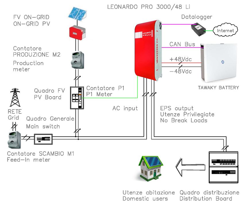
LEONARDO PRO II 3000/48 Li
                                                              Manuale utente                                           IT

                                              LEONARDO PRO II 3000/48 Li
                                                                                      • Funzione EPS anti-blackout con tempo di

                                                                                        ripristino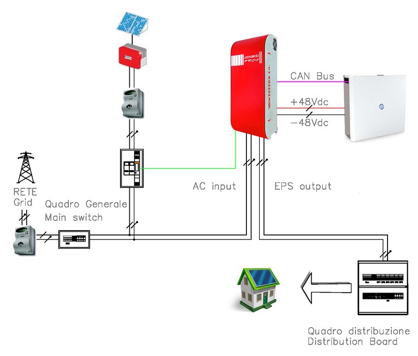
LEONARDO PRO II 3000/48 Li
                                                      Manuale utente                                               IT
Istruzioni di sicurezza
             Pericolo di esplosione a causa di scintille
             Pericolo di folgorazione
             ATTENZIONE: non sollevare oggetti pesanti senza assistenza
Generale
•   Si consiglia di leggere attentamente questo manuale prima di installare e utilizzare il prodotto.
•   L’installazione e la manutenzione del prodotto deve essere svolta solo da personale qualificato.
•   Questo prodotto è progettato e testato in conformità agli standard internazionali. L'apparecchiatura deve essere
    utilizzata solo per l'applicazione per cui è stata progettata.
•   Il prodotto è utilizzato in combinazione con una fonte di energia permanente (batteria). Anche se l'apparecchiatura
    è spenta, può verificarsi una tensione elettrica pericolosa ai terminali di ingresso e / o uscita. Spegnere sempre
    l’eventuale alimentazione AC, le stringhe fotovoltaiche e scollegare la batteria prima di eseguire la manutenzione.
•   Il prodotto non contiene parti interne riparabili dall'utente. Non rimuovere il pannello frontale e non mettere in
    funzione il prodotto se non sono montati tutti i pannelli.
•   Non utilizzare mai il prodotto in luoghi in cui potrebbero verificarsi esplosioni di gas o polvere.
•   Fare riferimento alle specifiche fornite dal produttore della batteria per assicurarsi che sia idonea all'uso con questo
    prodotto. Le istruzioni di sicurezza del produttore della batteria devono essere sempre osservate.

Installazione e manutenzione
•   Questo prodotto è un dispositivo di sicurezza di I classe (fornito con un terminale di terra per motivi di sicurezza). I
    suoi terminali di ingresso e / o uscita AC devono essere dotati di messa a terra ininterrotta per motivi di sicurezza.
    Un ulteriore punto di messa a terra si trova all'esterno del prodotto. Se si può presumere che la protezione di messa
    a terra sia danneggiata, il prodotto dovrebbe essere messo fuori servizio impedendo che possa entrare in funzione
    accidentalmente; contattare personale di manutenzione qualificato.
•   Assicurarsi che i cavi di collegamento siano dotati di fusibili e interruttori automatici. Non sostituire mai un dispositivo
    di protezione con un componente di un tipo diverso.
•   Controllare prima di accendere il dispositivo se la sorgente di tensione disponibile è conforme alle impostazioni di
    configurazione del prodotto come descritto nel manuale.
•   Installare il prodotto in un ambiente che garantisce il range operativo di temperatura. Assicurarsi che non ci siano
    sostanze chimiche, parti in plastica, tende o altri tessuti che possono infiammarsi nelle immediate vicinanze
    dell'apparecchiatura. Non utilizzarlo mai in un ambiente umido.
•   Assicurarsi che ci sia sempre sufficiente spazio libero intorno al prodotto per la ventilazione e che le aperture di
    ventilazione non siano bloccate.
•   Proteggere i moduli solari dalla luce incidente durante l'installazione.
•   Non toccare mai le estremità del cavo non isolate. Utilizzare solo strumenti isolati.
•   I collegamenti devono sempre essere eseguiti nella sequenza descritta in questo manuale.
•   L'installatore del prodotto deve fornire un mezzo (es. fermacavi) per impedire che la trazione dei cavi si trasmetta
    alle connessioni rovinandole.
•   Oltre a questo manuale, le operazioni di installazione del sistema devono includere un manuale di manutenzione
    della batteria applicabile al tipo di batterie utilizzate.

Trasporto e stoccaggio
•   Durante lo stoccaggio o il trasporto del prodotto, assicurarsi che l'alimentazione di rete e i cavi della batteria siano
    scollegati.
•   Nessuna responsabilità può essere accettata per danni in transito se l'attrezzatura non viene trasportata nella sua
    confezione originale.
•   Conservare il prodotto in un ambiente asciutto; vedere il range operativo di temperatura per evitare di danneggiare
    il prodotto.
•   Fare riferimento al manuale del produttore della batteria per informazioni su trasporto, conservazione, carica,
    ricarica e smaltimento della batteria.

Le indicazioni riportate nel manuale non sostituiscono le norme di sicurezza vigenti nel paese di installazione e le regole
dettate dal comune buonsenso.

                                                              2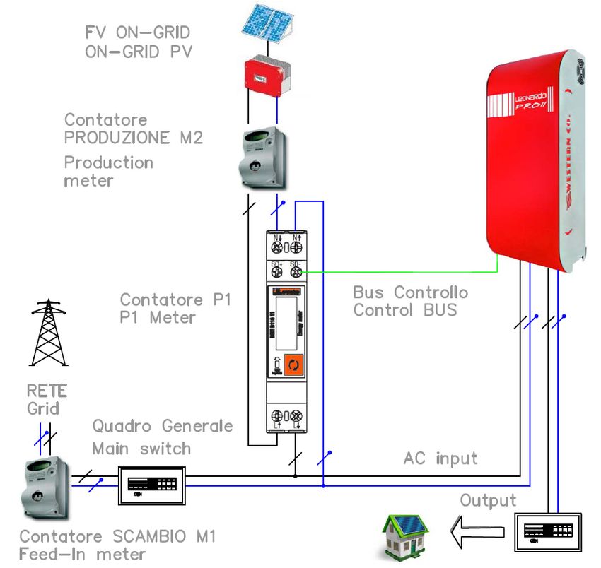
LEONARDO PRO II 3000/48 Li
                                                     Manuale utente                                               IT
FUNZIONAMENTO DEL LEONARDO PRO II 3000/48 Li
                              1-    Il Leonardo PRO II 3000/48 Li è progettato per accumulo di energia da impianti
                                   fotovoltaici esistenti, connessi alla rete ON-GRID;
                              2-   Normalmente l'apparecchio è nello stato ON-GRID, per autoconsumo diretto +
                                   accumulo, l'impianto FV esistente alimenta direttamente l'utenza domestica e il
                                   Leonardo PRO II 3000/48 Li prelevare energia dall'AC-INPUT, cercando di annullare
                                   o minimizzare la potenza immessa in rete;
                              3-   Se il consumo dell'abitazione supera la produzione dell'impianto FV, il Leonardo
                                   PRO II 3000/48 Li attua la funzione PEAK SHAVING per autoconsumo diretto +
                                   erogazione da batteria, l'impianto FV esistente alimenta direttamente l'utenza
                                   domestica ed il picco di consumo viene annullato o minimizzato dalla potenza
                                   prelevata dalla batteria;
                              4-   In caso di batteria completamente carica il sistema di gestione non potrà più
                                   assorbile l'energia direttamente prodotta dall'impianto FV esistente, che sarà
                                   direttamente immessa in rete, modalità FEED-IN;
                              5-   Di notte, quando non abbiamo più potenza FV prodotta, il convertitore eroga la
                                   potenza richiesta dalle utenze, con il sostegno della rete elettrica in caso di richiesta
                                   superiore alle capacità dell'apparecchio;
                              6-   In caso di BLACK-OUT le utenze privilegiate collegate sulla linea EPS, vengono
                                   alimentate creando una rete isolata OFF-GRID.

    Fig.1 Pannello frontale

                                            Fig.2 Schema di principio con uscita EPS

                                                               3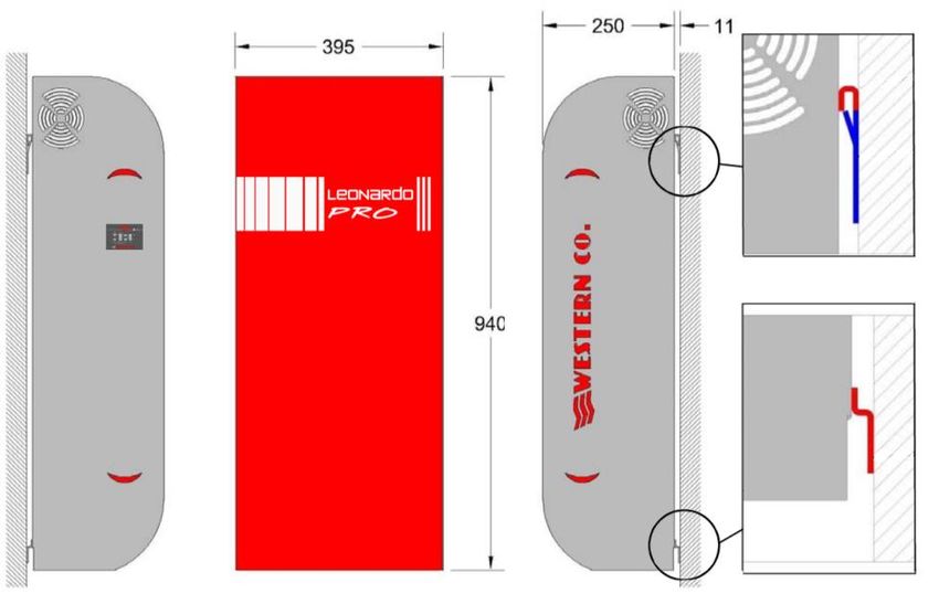
LEONARDO PRO II 3000/48 Li
                                                     Manuale utente                                            IT
SCHEMA INTERNO

                                                                                                       IMPIANTO FV
                                                                  AC                                   ESISTENTE
                    CONTATORE
                    ENERGIA
                                                                            DC
                    INCENTIVATA M2
                                                                 INVERTER FV
                                                                                                          8
                                        KWh              7        ESISTENTE

                                                                                                          IMPIANTO
             CONTATORE                                                                                   DOMESTICO
             ENERGIA                      Contatore di                           DATALOGGER
             SCAMBIATA M1                CONTROLLO P1

                                               5                                      6

                  KWh
                                              ACIN                                            EPSOUT
  RETE DI
  DISTRIBUZIONE
                                                                  ACin ACout

                                         2
                                               INPUT RELE'                          INVERTER
                                                                 AC               BIDIREZIONALE
                                                                                     ISOLATO
                   CAN BUS            ENERGY
                                      MANAGER
                                                                            DC
                                                                                          1
                                          4

  BATTERY                                           IBATT
       3                         LEONARDO PRO II
                                                     Fig.3 Schema interno
1. Inverter bidirezionale isolato: si occupa della carica e della scarica della batteria in accordo con il profilo di
   management, riceve il set-point della potenza di carica e scarica dall'energy manager, la potenza nominale in scarica è
   di 2,4kW la potenza nominale in carica è di 2,1kW;
2. Relè di ingresso: si occupa di connettere l'inverter in parallelo con la rete On-Grid, è responsabile dello sgancio della
   rete in caso di parametri fuori specifica (tensione e frequenza);
3. Batteria: è il sistema di accumulo elettrochimico a 48V con il suo profilo di gestione. Il Leonardo PRO 3000/48 4K Li
   possiede un cavo di comunicazione con CAN BUS, con connessione diretta di tipo RJ45, al sistema di gestione interna
   della batteria TAWAKI;
4. Energy Manager: determina il set-point per la potenza di carica e scarica in funzione della produzione dell'impianto
   FV esistente e del consumo dell'impianto domestico;
5. Contatore di controllo P1: è un contatore ad inserzione diretta, installabile in qualsiasi quadro o centralino con
   interfaccia di comunicazione impulsiva;
6. Datalogger: è il sistema di acquisizione dei dati per monitoraggio ed impostazione da remoto, è connesso ad Internet;
7. Inverter FV Esistente: è l'inverter dedicato al fotovoltaico per la produzione dell'energia incentivata, è dichiarato al
   GSE nella pratica di incentivazione;
8. Impianto FV Esistente: è il campo fotovoltaico esistente, è dichiarato al GSE nella pratica di incentivazione.

                                                             4
LEONARDO PRO II 3000/48 Li
                                               Manuale utente                                                   IT
SCHEMA DI COLLEGAMENTO

 Quadro FV:
                                             INVERTER DC/AC CON TRAFO              BANCO BATTERIE LITIO LG CHEM, TAWAKI
 - Contatore Controllo P1
                                             - Potenza continua 3000 VA            - Tensione di sistema 48Vdc
 - Misura produzione FV
                                             - Potenza di carica 2100W             - Capacità consigliata impianto FV ON-GRID
                                             - Ingresso AC                         4kWp: n.1 RESU 6.5, n.1 MAUI 4.3
                                             - Batteria 48Vdc                      6kWp: n.2 RESU 10, n.2 MAUI 4.3
                                             - Corrente Ingressi 32A

    PROTEZIONE AC INGRESSO
    - interruttore magnetotermico-
    differenziale
    - corrente nominale I = 32A
    - corrente differenziale Id = 0,3A

                                             PROTEZIONE AC USCITA
                                             - interruttore magnetotermico-
                                             differenziale
                                             - corrente nominale I = 32A
                                             - corrente differenziale Id = 0,03A

                                           Fig.4 Schema di collegamento

                                                        5
LEONARDO PRO II 3000/48 Li
                                                        Manuale utente                                                   IT
PROTEZIONI ESTERNE
Protezioni lato Corrente Alternata
Il Leonardo PRO II 3000/48 Li è dotato di un'uscita in corrente alternata EPS ed una linea di ingresso in corrente alternata
AC-IN.
Essendo l'apparecchio dotato di collegamento a terra del conduttore NEUTRO - sistema TT, la linea di uscita in corrente
alternata AC-OUT può essere protetta con un interruttore magnetotermico-differenziale USCITA di tipo AC, con corrente
nominale In=32A e corrente differenziale Id=0,03A ( questo interruttore di solito è già presente nel quadro di distribuzione
dell'abitazione come protezione dai contatti indiretti, con corrente differenziale 30mA).
La linea di ingresso in corrente alternata AC-IN può essere protetta con un interruttore magnetotermico-differenziale
INGRESSO di tipo AC, con corrente nominale In=32A e corrente differenziale Id=0,3A, questo interruttore può essere
inserito in un quadro generale aggiuntivo o, se possibile, nel quadro di distribuzione esistente nell'abitazione.
E' bene prevedere un deviatore a tre posizioni I-0-II, che in caso di malfunzionamento del sistema possa collegare
direttamente AC-OUT e AC-IN ed effettuare il BY-PASS del sistema.

Protezioni lato Corrente Continua
Il collegamento del banco batterie è effettuato tramite il cavo di collegamento di potenza di dotazione ed il cavo di
comunicazione CAN, inoltre l'interruttore di sezionamento del polo positivo a bordo dell'inverter provvede all'attivazione
in completa sicurezza.

 Fig.5 Cavo di potenza        Fig.6 Cavo di comunicazione CAN su batteria LG Chem   Fig.7 Cavo di comunicazione CAN su batteria Tawaki

INTERRUTTORE DI SEZIONAMENTO INVERTER
L'attivazione dell'interruttore di sezionamento del polo positivo realizza l'accensione dell'inverter in completa sicurezza.

                ATTENZIONE: nella sequenza di ACCENSIONE dell'apparecchio l'interruttore di
                sezionamento INVERTER deve essere attivato DOPO rispetto all'interruttore di
                accensione della BATTERIA.
                Per lo SPEGNIMENTO o il RESET della batteria aprire per PRIMO l'interruttore
                di sezionamento INVERTER.

                                                                                                          Fig.8 Sezionatore INVERTER

Anche la batteria TAWAKI possiede un interruttore di sezionamento e protezione automatico.

             ATTENZIONE: effettuare l'attivazione dell'interruttore di batteria solo dopo aver collegato il
             cavo di comunicazione CAN ed attivato l'interruttore di SEZIONAMENTO INVERTER.

                                                                 6
LEONARDO PRO II 3000/48 Li
                                                    Manuale utente                                          IT
INSTALLAZIONE CONTATORE CONTROLLO P1
Il Contatore di controllo P1 prevede un collegamento diretto dei cavi di alimentazione AC dell'impianto FV esistente, al
fine di misurare la potenza FV Prodotta. Le morsettiere di ingresso ed uscita possono ospitare cavi di sezione fino a 10
mmq ed una corrente massima pari a 40A.

                                                                          CAVO 2 POLI

                                              Fig.9 Schema installazione Contatore P1

ATTENZIONE: Lettura Potenza FV Prodotta
Il contatore P1 contabilizza la produzione dell'impianto FV esistente, se durante la produzione (quindi durante il
giorno) si visualizza Err0r 3, è stato effettuato un collegamento AC errato.
Mentre se durante la notte, quindi in caso di produzione nulla e leggero Auto-Consumo dell'inverter di produzione FV, si
visualizza Err0r 03, questa è un normale stato di funzionamento

                                              Fig.10 Errore 03 su Power Meter

ERROR 03: di giorno con produzione FV => ERRATO collegamento AC-IN / AC OUT
ERROR 03: di notte o senza produzione FV => NORMALE segnalazione per Auto-Consumo Inverter FV o altri consumi.

                                                             7
LEONARDO PRO II 3000/48 Li
Manuale utente IT
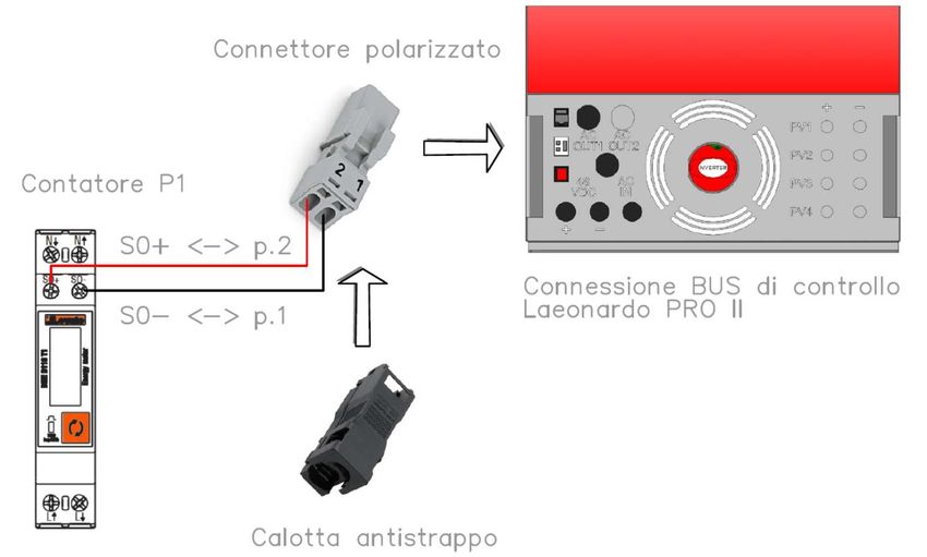
Il contatore di controllo P1, può essere installato all'interno di quadri esistenti con montaggio modulare singolo posto 1U,
secondo lo schema in Fig. 9. Il contatore deve essere collegato al Leonardo PRO II, attraverso lo schema seguente:
PRESA POLARIZZATA
Distanza consigliata:
25 m
Fig.11 Schema cavo BUS controllo al Contatore P1
COLLEGAMENTO LEONARDO DATALOGGER *opzionale
Il Leonardo PRO II 3000/48 Li possiede un collegamento diretto per il sistema di monitoraggio e controllo Leonardo
Datalogger, seguire il manuale di collegamento ed installazione del Leonardo Datalogger relativamente alla sezione di
collegamento Internet ed alimentazione, utilizzare un cavo UTP di categoria 5 o superiore (fornito a corredo del Leonardo
Datalogger) per il collegamento della comunicazione seriale.
CONNESSIONE CAVO DATALOGGER
- utilizzare il cavo patch nero in
dotazione;
- utilizzare la presa RJ45 - LOG di
colore NERO.
CONNESSIONE
INTERNET
CAVO UTP - CONNESSIONE SERIALE
Cablaggio tramite cavo PATCH nero
LEONARDO DATALOGGER
ALIMENTAZIONE
DATALOGGER
Fig.12 Collegamento Leonardo Datalogger
8LEONARDO PRO II 3000/48 Li
Manuale utente IT
INSTALLAZIONE MECCANICA
L'installazione dell'apparecchiatura va eseguita da personale autorizzato e specializzato ad eseguire tale compito, dopo
adeguato addestramento per la messa in funzione di apparecchiature di questo tipo.
L'installazione va effettuata con l'apparecchiatura sconnessa dalla rete (connessioni di corrente alternata) e sconnessa
dal banco batterie di accumulo (sezionatore DC aperto).
1. Installare il Leonardo PRO II 3000/48 Li in un luogo asciutto ed adeguatamente arieggiato, fissato su di una
superficie non infiammabile e posizionato in modo da lasciare uno spazio privo di ostacoli di almeno 10cm
nell’intorno del dispositivo che ne permette il raffreddamento per convezione forzata dell’aria.
2. Fissare a muro la staffa di supporto (fornita in dotazione) tramite i tasselli e le viti fornite in dotazione;
successivamente agganciare l’inverter tramite la piastra ad uncino posta nella parte superiore dell’apparecchio.
Infine fissare l’inverter alla parete utilizzando i fori predisposti nella parte inferiore dell’apparecchio. Il tutto
come indicato in Fig. 13.
PIASTRA AD UNCINO
parte superiore dell’inverter
STAFFA DI
SUPPORTO
PIASTRA parte
inferiore dell’inverter
Fig.13 Montaggio a parete
9LEONARDO PRO II 3000/48 Li
Manuale utente IT
CABLAGGIO INVERTER
Effettuare i collegamenti elettrici dell'inverter, seguendo strettamente il seguente ordine:
1. cavo batteria positivo (vedi collegamento nella sezione Protezioni Lato Corrente Continua);
2. cavo batteria negativo;
3. collegare il cavo di comunicazione CAN; (vedi Protezioni Lato Corrente Continua)
4. collegare il cavo BUS di controllo dal contatore P1, tramite connettore polarizzato; (vedi Schema cavo BUS di
controllo al contatore P1)
5. collegare il PLUG Data-logger; (vedi Schema installazione Data-Logger opzionale)
6. portare le protezioni lato corrente alternata su AC-IN e EPS-OUT in posizione OFF (vedi paragrafo
PROTEZNIONI ESTERNE);
7. collegare ingresso AC-IN su connessione AC Input tramite connettori AC plug and play tipo RST;
8. collegare uscita EPS-OUT delle UTENZE PRIVILEGIATE su connessione AC Output tramite connettori AC plug
and play tipo RST.
PLUG DATA-LOGGER AC OUT EPS - PRIVILEGIATA AC INPUT
NERO (*opzionale) Cablaggio tramite connettori plug Cablaggio tramite connettori plug
and play a 3 poli - 6mm^2 and play a 3 poli - 6mm^2
PLUG BUS DI
CONTROLLO P1
PULSANTE
RESET
Ingresso DC Batteria
Cavo 1,5 m-Sez. 25 mmq
Cavo Comunicazione CAN
Lunghezza cavo 1,5 m
Fig.14 Cablaggio Inverter
10LEONARDO PRO II 3000/48 Li
Manuale utente IT
AVVIO DEL SISTEMA
Effettuare l'attivazione del sistema, seguendo strettamente il seguente ordine di avvio:
1. portare le protezioni lato corrente alternata su AC-IN in posizione ON, verificando l'accensione del dispositivo
Energy Manager, presente lateralmente al Leonardo PRO II 3000/48 Li;
2. attivare l'interruttore di accensione BATTERIA - posizione ON;
3. attivare l'interruttore di sezionamento INVERTER - posizione ON;
4. portare le protezioni lato corrente alternata su EPS-OUT in posizione ON e visualizzare l'eventuale consumo
dell'abitazione;
5. Chiudere il sezionatore dell'impianto FV ESISTENTE e verificare che la produzione sia correttamente visualizzata
dal contatore P1 con l'assenza dell'errore 03;
Produzione in kW rilevata Errore 03 -> consumo rilevato!
11LEONARDO PRO II 3000/48 Li
Manuale utente IT
6. Verificare l'accensione del LED AC CHARGE ed eventualmente quella del LED INVERTER.
CARICA CONSUMO < PRODUZIONE PEAK SHAVING CONSUMO > PRODUZIONE
SEGNALAZIONI ENERGY MANAGER
Le segnalazioni a LED sull'Energy Manager possono essere interpretate come di seguito:
• Led AC CHARGE acceso → ricarica da impianto fotovoltaico esistente
• Led AC IN acceso → presenza rete all'ingresso AC-IN dell'inverter Leonardo PRO
• Led BATTERY acceso → tensione delle batterie
• Led BYPASS acceso → funzionamento in modalità “ON GRID” in parallelo con la rete
• Led LOAD acceso → potenza dei consumi sull' uscita AC-OUT
• Led STATUS verde → normale funzionamento ON
Fig.15 segnalazioni su Energy Manager
Tabella segnalazione LED STATUS
LED STATUS
Led VERDE: normale stato di funzionamento attivo ON.
LED STATUS
Led VERDE + n.1 lampeggio ARANCIO ogni 10 Secondi: stato di BMS FULL-BATTERY
LED STATUS
Led VERDE + n.2 lampeggi ARANCIO ogni 10 Secondi: stato di BMS LOW-BATTERY
LED STATUS
Led ROSSO n.1 lampeggio ogni 10 Secondi: stato di allarme SOVRA-TEMPERATURA.
LED STATUS
Led ROSSO n.2 lampeggi ogni 10 Secondi: stato di allarme LOW-BATTERY.
LED STATUS
Led ROSSO n.3 lampeggi ogni 10 Secondi: stato di allarme OVER-LOAD.
Tab.1 Segnalazione LED STATUS
ATTENZIONE: in caso di BLOCCO dell'inverter, nessuna tensione di alimentazione sull'uscita AC-OUT,
causa una delle tre condizioni di anomalia indicate in Tab. 1, è necessario un RIAVVIO dell'apparecchio,
utilizzando il tasto di RESET posto sul fondo dell'apparecchio (Fig.14).
12LEONARDO PRO II 3000/48 Li
Manuale utente IT
COLLAUDO MACCHINA
Per verificare il corretto funzionamento del sistema si possono effettuare delle prove di funzionamento delle condizioni
di passaggio giorno/notte e passaggio notte/giorno. È necessario effettuare il collaudo durante il giorno con un buon
irraggiamento solare.
Simulazione passaggio notte/giorno
Accendere l’impianto fotovoltaico e verificare che:
• la potenza dell'impianto fotovoltaico sia correttamente rilevata dal Contatore P1
• Il LED AC CHARGE sia acceso
• Il LED INVERTER si accende se il consumo è superiore alla produzione (PEAK SHAVING)
Simulazione passaggio giorno/notte
Spegnere l’impianto fotovoltaico e verificare che:
• La potenza del Contatore P1 è 0 kW ed eventualmente viene rilevato Errore 03 (normale autoconsumo INVERTER)
• Il LED AC CHARGE spento (il rilevamento della potenza viene effettuato in circa 30 secondi)
• Il LED INVERTER è acceso per annullare i prelievi dalla rete
• Non si hanno segnalazioni di batteria scarica
Effettuare alcune prove di carico.
Accendere un carico con spunto superiore a 2500W. Verificare che l’inverter rimanga nello stato di BYPASS ed INVERTER
accesi, la potenza in esubero rispetto alle capacità della macchina viene prelevata dalla rete o dalla produzione
dell'impianto FV esistente. Verificare la tenuta della tensione delle batterie.
EVENTUALI PROBLEMATICHE E SOLUZIONI
• Led AC IN spento -> Verificare la tensione in ingresso e il cablaggio del connettore AC-IN del Leonardo PRO 3000.
• Assenza tensione in uscita EPS-OUT -> Verificare il cablaggio del connettore AC-OUT. Verificare se l’Energy
Manager presenta entrambi i led BYPASS e INVERTER spenti.
• Entrambi i Led “bypass” e “inverter” spenti -> Provvedere a resettare l’inverter eseguendo la procedura come
da manuale. Ad inverter spento girare solo il sezionatore DC delle batterie e verificare l’accensione del Led
BATTERY e del Led INVERTER. Verificare l’integrità di eventuali fusibili DC di protezione. Se il problema permane
si consiglia di contattare l’assistenza tecnica Western CO.
• Led AC CHARGE sempre spento -> Verificare il cablaggio AC per la misura della potenza FV prodotta.
• Led STATUS spento. Effettuare reset inverter come da manuale.
• Led STATUS 1 lampeggio arancione -> Il BMS della batteria al LITIO rileva batteria carica e la funzione carica AC
CHARGE viene disabilitata, attendere la scarica.
• Led STATUS 2 lampeggi arancioni -> Il BMS della batteria al LITIO rileva batteria scarica e la funzione erogazione
INVERTER viene disabilitata, attendere la ricarica.
• Errore 03 su POWER METER di GIORNO -> probabile inversione del cablaggio sulle morsettiere di ingresso e uscita
AC del contatore P1, oppure un carico utilizzatore annulla la potenza FV misurata.
• Errore 03 su POWER METER di NOTTE -> normale segnalazione dovuta all'autoconsumo notturno dell'inverter
FV.
SEGNALAZIONI STATO BATTERIA E CARICO
Tabella Stato di carica e potenza di uscita
13LEONARDO PRO II 3000/48 Li
Manuale utente IT
Stato di carica SOC livello 4, l'energia
effettivamente stoccata in batteria si
Potenza di uscita LOAD livello 4, la
trova in un intervallo compreso tra
potenza elettrica delle utenze in uscita
70% - 100% della propria capacità
è superiore al livello di 4000W.
nominale (tensione maggiore di
54,4V).
Stato di carica SOC livello 3, l'energia
Potenza di uscita LOAD livello 3, la
effettivamente stoccata in batteria si
potenza elettrica delle utenze in uscita
trova in un intervallo compreso tra
è compresa in un intervallo di 2200W
50% - 70% della propria capacità
- 4000W.
nominale (tensione maggiore di 48V).
Stato di carica SOC livello 2, l'energia
Potenza di uscita LOAD livello 2, la
effettivamente stoccata in batteria si
potenza elettrica delle utenze in uscita
trova in un intervallo compreso tra
è compresa in un intervallo di 1300W
40% - 50% della propria capacità
- 2200W.
nominale (tensione maggiore di 46V).
Stato di carica SOC livello 1, l'energia
Potenza di uscita LOAD livello 1, la
effettivamente stoccata in batteria si
potenza elettrica delle utenze in
trova in un intervallo compreso tra
uscita è compresa in un intervallo di
20% - 40% della propria capacità
200W - 1300W.
nominale (tensione maggiore di 42V).
Tab.2 Stato di Carica e Potenza di Uscita
Poiché l’apparecchio viene dotato di cavo per collegamento batteria di lunghezza 1,5m e sezione 25mmq è assolutamente
raccomandato installare il banco batteria ad una distanza tale da mantenere il cavo originale per il collegamento.
Aumentare la distanza con il banco batterie comporta un aumento della caduta di tensione sul cavo in fase di
funzionamento.
Utilizzare il cavo in dotazione per effettuare il collegamento del cavo di comunicazione CAN direttamente sulla batteria.
Si raccomanda l’installazione dell’apparecchio su parete solida in posizione verticale, al fine di assicurare un adeguato
ricircolo di aria, dovuta alla ventilazione forzata dell’apparecchio. Per tale motivo è inoltre da evitare l’installazione in luoghi
ricchi di polvere e sporco.
14LEONARDO PRO II 3000/48 Li
Manuale utente IT
CARATTERISTICHE ELETTRICHE
Leonardo PRO
3000 / 48V Li
Potenza nominale Pnom 3kVA
Potenza continua a 25°C Pcon1 2.4kW
Potenza continua a 40°C Pcon2 2.2kW
Potenza di picco Pmax 5.5kW
Tensione di batteria Vbatt 48V
Intervallo di batteria Vdc 40 - 66V
Tensione e Frequenza CA Vnom 230Vac - 50Hz
Range di tensione CA Vac 187 - 265Vac
Corrente di Ingresso CA Iac 32A
INVERTER
Distorsione armonica Thd < 3%
Fattore di potenza nominale Pi 1
Efficienza massima DC->AC Eds 95%
Carico collegabile su EPS Out Eps 7kW
Tempo di trasferimento EPS su Blackout
Tsw 10mS
rete
Potenza nominale in Blackout Pbout 3kW
Assorbimento in by-pass Pbp < 3W
Topologia Top Trasformatore di isolamento toroidale
Raffreddamento Ven Ventilazione forzata
Misura produzione FV Mis Meter 40A ad insersione diretta
Potenza di carica massima Pch 2.1kW
AC CHARGER
Corrente di carica massima Ich 35A
Efficienza massima AC->DC Ech 95%
Curva di ricarica Alg Auto-Adattativa
Comunicazione batteria Com CAN BUS
Min Tip Max
2
Sezione dei cavi batteria 25mm
Lunghezza cavi batteria 1.5mt
ENCLOSURE
Temperatura ambientale -10°C a +60°C
Grado di protezione IP20
Dotazioni Sezionatore batteria da 275A
Dimensioni 395x940x250 mm
Peso 25.5kg
Tab.3 Caratteristiche elettriche
15LEONARDO PRO II 3000/48 Li
Manuale utente IT
DIMENSIONI MECCANICHE E PESI
Leonardo PRO II 3000/48 Li = 25,5 kg
Fig.16 Dimensioni Inverter
GARANZIA DI LEGGE
Western CO. srl garantisce la buona qualità e la buona costruzione dei Prodotti obbligandosi, durante il periodo di garanzia
di 5 (cinque) anni, a riparare o sostituire a sua sola discrezione, gratuitamente, quelle parti che, per cattiva qualità del
materiale o per difetto di lavorazione si dimostrassero difettose.
Il prodotto difettoso dovrà essere rispedito alla Western CO. srl o a società delegata dalla Western CO. srl a fare assistenza
sul prodotto, a spese del cliente, assieme ad una copia della fattura di vendita, sia per la riparazione che la sostituzione
garantita. I costi di re-installazione del materiale saranno a carico del cliente.
La Western CO. srl sosterrà le spese di re spedizione del prodotto riparato o sostituito.
La garanzia non copre i Prodotti che, in base a nostra discrezione, risultino difettosi a causa di naturale logoramento,
che presentino guasti causati da imperizia o negligenza del cliente, da imperfetta installazione, da manomissioni o
interventi diversi dalle istruzioni da noi fornite .
La garanzia decade altresì in caso di danni derivanti da:
-trasporto e/o cattiva conservazione del prodotto.
-causa di forza maggiore o eventi catastrofici (gelo per temperature inferiori a -20°C, incendio, inondazioni, fulmini, atti
vandalici, ecc …).
Tutte le sopraccitate garanzie sono il solo ed esclusivo accordo che soprassiede ogni altra proposta o accordo verbale o
scritto e ogni altra comunicazione fatta tra il produttore e l’acquirente in rispetto a quanto sopra.
Per qualsiasi controversia il Foro competente è Ascoli Piceno. Per ulteriori informazioni, consultare il documento
“Garanzia Leonardo” al seguente link: https://www.western.it/garanzia/
SMALTIMENTO DEI RIFIUTI
La Western CO. in qualità di produttore del dispositivo elettrico descritto nel presente manuale,
ed in conformità al D.L 25/07/05 n 151, informa l’acquirente che questo prodotto, una volta
dismesso, deve essere consegnato ad un centro di raccolta autorizzato oppure, in caso di
acquisto di apparecchiatura equivalente può essere riconsegnato a titolo gratuito al distributore
della apparecchiatura nuova.
Le sanzioni per chi abusivamente si libera di un rifiuto elettronico saranno applicate dalle singole
amministrazioni comunali.
WESTERN CO. S.r.l.
Via Pasubio, 1
63074 San Benedetto del Tronto (AP)
tel. (+39) 0735 751248 fax. (+39) 0735 751254
e-mail: info@western.it
web: www.western.it
16LEONARDO PRO II 3000/48 Li
User manual EN
LEONARDO PRO II 3000/48 Li
• LITHIUM storage system for EXISTING
photovoltaic systems
• EPS anti-blackout function with recovery
timeLEONARDO PRO II 3000/48 Li
User manual EN
Safety instructions
Danger of explosion from sparking
Danger of electric shock
WARNING: do not lift heavy objects unassisted.
In general
• Read the installation instructions before commencing installation activities.
• The product installation and maintenance must be performed only by qualified personnel.
• This product is designed and tested in accordance with international standards. The equipment should be used for
the designed application only.
• The product is used in combination with a permanent energy source (battery). Even if the equipment is switched off,
a dangerous electrical voltage can occur at the input and/or output terminals. Always switch the AC power off,
Photovoltaic strings and disconnect the battery before performing maintenance.
• The product contains no internal user-serviceable parts. Do not remove the frontal panel and do not put the product
into operation unless all panels are fitted.
• Never use the product at sites where gas or dust explosions could occur.
• Refer to the specifications provided by the manufacturer of the battery to ensure that it is suitable for use with this
product. The battery manufacturer’s safety instructions should always be observed.
Installation and maintenance
• This product is safety class I device (supplied with a ground terminal for safety purposes). Its AC input and/or output
terminals must be provided with uninterruptible grounding for safety purposes. An additional grounding point is
located in the outside of the product. If it can be assumed that the grounding protection is damage, the product
should be taken out of operation and prevented from accidentally being put into operation again; contact qualified
maintenance personnel.
• Ensure that the connection cables are provided with fuses and circuit breakers. Never replace a protective device by
a component of a different type.
• Check before switching the device on whether the available voltage source conforms to the configuration settings of
the product as described in the manual.
• Install the product in an environment that guarantees the operating temperature range. Ensure that there are no
chemicals, plastic parts, curtains or other fabrics that can ignite in the immediate vicinity.
• Ensure that there is always sufficient free space around the product for ventilation, and that ventilations openings
are not blocked.
• Protect the solar modules from incident light during installation.
• Use only insulated tools. Never touch uninsulated cable ends.
• Connections must always be made in the sequence described in this manual.
• The installer of the product must provide a means for cable stain relief to prevent the transmission of stress to the
connections.
• In addition to this manual, the system operations or service manual must include a battery maintenance manual
applicable to the type of batteries used.
Transport and storage
• On storage or transport of the product, ensure that the mains supply and battery leads are disconnected.
• No liability can be accepted for damage in transit if the equipment is not transported in its original packaging.
• Store that product in a dry environment; see the operating temperature range to avoid damaging the product.
• Refer to the battery manufacturer’s manual for information on transport, storage, charging, recharging and disposal
of the battery.
Recommendations given in this manual do not replace the safety regulations of the country of installation and the rules
dictated by common sense.
2LEONARDO PRO II 3000/48 Li
User manual EN
LEONARDO PRO II 3000/48 Li WORKING PRINCIPLES
1- The Leonardo PRO II 3000/48 Li is designed to store energy from existing
photovoltaic systems connected to the ON-GRID network;
2- Normally the device is in ON-GRID state, for direct self-consumption + storage, the
existing PV system directly supplies the domestic user and the Leonardo PRO II
3000/48 Li withdraw energy from the AC-INPUT, trying to cancel or minimize the
power fed into the network;
3- If the consumption of the dwelling exceeds the production of the PV plant, the
Leonardo PRO II 3000/48 Li implements the PEAK SHAVING function for direct self-
consumption + battery supply, the existing PV system directly supplies the
domestic user and the peak consumption is canceled or minimized by the power
taken from the battery;
4- In case of fully charged battery the management system can no longer absorb the
energy directly produced by the existing PV plant, which will be directly fed into the
grid, FEED-IN mode;
5- At night, when we no longer have the PV power produced, the converter supplies
the power required by the utilities, with the support of the electricity grid in the
event of demand exceeding the capacity of the appliance;
6- In case of BLACK-OUT, the privileged users connected to the EPS line are powered
by creating an isolated OFF-GRID network.
Pic.1 Front Panel
Pic.2 Scheme of principle with EPS output
3LEONARDO PRO II 3000/48 Li
User manual EN
INTERNAL DIAGRAM
EXISTING PV
AC PLANT
INCENTIVIZED
DC
ENERGY METER M2
INVERTER FV
8
KWh 7 ESISTENTE
DOMESTIC
DATALOGGER PLANT
CONTROL METER
EXCHANGED ENERGY P1
METER M1
5 6
KWh
ACIN EPSOUT
POWER GRID
ACin ACout
2
INPUT RELAY ISOLATED
AC BIDIRECTIONAL
INVERTER
CAN BUS ENERGY
MANAGER
DC
1
4
BATTERY IBATT
3 LEONARDO PRO II
Pic.3 Internal Diagram
1. Isolated bidirectional inverter: takes charge of charging and discharging the battery in accordance with the
management profile, receives the set-point of the charge and discharge power from the energy manager, the nominal
discharge power is 2.4 kW nominal power in charge is 2.1kW;
2. Input relay: it takes care of connecting the inverter in parallel with the On-Grid network; it is responsible for
disconnecting the grid in case of out-of-specification parameters (voltage and frequency);
3. Battery: is the 48V electrochemical storage system with its management profile. The Leonardo PRO 3000/48 4K Li has
a communication cable with CAN BUS, with direct connection of type RJ45, to the internal management system of the
TAWAKI battery;
4. Energy Manager: determines the set-point for the charging and discharging power according to the production of the
existing PV plant and the consumption of the domestic system;
5. Control counter P1: it is a direct insertion counter, which can be installed in any panel or switchboard with a pulse
communication interface;
6. Datalogger: it is the data acquisition system for remote monitoring and setting, it is connected to Internet;
7. Existing PV inverter: it is the inverter dedicated to photovoltaics for the production of incentivized energy, it is declared
to the GSE in the incentive practice;
8. Existing PV Plant: it is the existing photovoltaic field, it is declared to the GSE in the incentive practice.
4LEONARDO PRO II 3000/48 Li
User manual EN
CONNECTION DIAGRAM
PV panel:
- P1 Control Counter DC / AC INVERTER WITH TRAFO
- Continuous power 3000 VA LITHIUM BATTERY LG CHEM, TAWAKI
- PV production measurement - 48Vdc system voltage
- 2100W charging power
- AC input - Recommended capacity of PV plant ON-GRID
- 48Vdc battery 4kWp: n.1 RESU 6.5, n. 1 MAUI 4.3
- Current Inputs 32A 6kWp: n.2 RESU 10, n.2 MAUI 4.3
AC INPUT PROTECTION
- magnetothermic-differential
switch
- rated current I = 32A
- differential current Id = 0.3A
AC OUTPUT PROTECTION
- magnetothermic-differential
switch
- rated current I = 32A
- differential current Id = 0.03A
Pic.4 Connection Diagram
5LEONARDO PRO II 3000/48 Li
User manual EN
EXTERNAL PROTECTIONS
Alternating current side protections
The Leonardo PRO II 3000/48 Li is equipped with an alternating current output and an AC-IN line of AC input.
Since the device is equipped with a ground connection of the NEUTRO - TT system, the AC-OUT alternating current output
line can be protected by an AC-type rated thermal-differential circuit breaker, with rated current In = 32A and differential
current Id = 0.03A (this switch is usually already present in the house distribution panel as protection against indirect
contacts, with 30mA differential current).
The AC-IN alternating current input line can be protected with an magnetothermal-differential switch AC type INPUT,
with rated current In = 32A and differential current Id = 0.3A, this switch can be inserted in an additional general panel or
, if possible, in the framework of distribution existing in the home.
It is advisable to use a three-position diverter I-0-II, which in case of system malfunction can directly connect AC-OUT and
AC-IN and make the system BY-PASS.
Continuous Current side protections
The connection of the battery bank is made by the power connection cable provided and the CAN communication cable,
moreover the isolating switch of the positive pole on board of the inverter provides the activation in complete safety.
Pic.5 Power Cable Pic.6 CAN communication cable on LG Chem battery Pic.7 CAN communication cable on Tawaki battery
INVERTER SECTIONING SWITCH
Activation of the positive pole isolation switch activates the inverter ignition in complete safety.
CAUTION:in the appliance ON sequence the INVERTER disconnection switch
must be activated AFTER the BATTERY switch.To turn the battery OFF or
RESET, open the INVERTER sectioning switch for FIRST.
Pic.8 INVERTER circuit breaker
The TAWAKI battery also has a circuit breaker and automatic protection switch.
CAUTION: carry out the activation of the battery switch only after connecting the CAN
communication cable and activating the INVERTER SWITCHING switch
6LEONARDO PRO II 3000/48 Li
User manual EN
P1 CONTROL COUNTER INSTALLATION
The P1 control counter provides a direct connection of the AC power supply cables of the existing PV system, in order to
measure the produced PV power. The input and output terminal blocks can house section cables up to 10 mmq and a
maximum current of 40A.
2 POLE CABLE
Pic.9 Installation diagram Counter P1
CAUTION: Reading Produced PV Power
The counter P1 accounts for the production of the existing PV plant, if Err0r 3 is displayed during production (therefore
during the day), an incorrect AC connection has been made.
While if at night, then in case of zero and light production Self-Consumption of the PV production inverter, Err0r 03 is
displayed, this is a normal operating state.
Pic.10 Error 03 on Power Meter
ERROR 03: during the day with PV production => INCORRECT AC-IN / AC OUT connection
ERROR 03: at night or without PV production => NORMAL signaling for Auto-Consumption PV inverter or other
consumption.
7LEONARDO PRO II 3000/48 Li
User manual EN
The control counter P1 can be installed inside panels with a single 1U modular block, according to the diagram in Pic. 9.
The meter must be connected to Leonardo PRO II, following the following scheme.
POLARIZED JACK
Recommended distance:
25 m
Pic.11 BUS cable diagram control at counter P1
LEONARDO DATALOGGER * connection optional
The Leonardo PRO II 3000/48 Li has a direct connection to the Leonardo Datalogger monitoring and control system, follow
the connection and installation manual of the Leonardo Datalogger with regard to the Internet connection and power
supply section, use a UTP cable of category 5 or higher (supplied with the Leonardo Datalogger) for the connection of the
serial communication.
CONNECTION CABLE DATALOGGER
-use the supplied black patch cable;
- use the RJ45 - LOG socket in BLACK
color.
INTERNET
CONNECTION
CABLE UTP - SERIAL CONNECTION
Wiring via black PATCH cable
LEONARDO DATALOGGER
DATALOGGER
POWER SUPPLY
Pic.12 Leonardo Datalogger connection
8LEONARDO PRO II 3000/48 Li
User manual EN
MECHANICAL INSTALLATION
The installation of the equipment must be performed by authorized and specialized personnel to perform this task,
after appropriate training for the commissioning of equipment of this type.
The installation must be carried out with the equipment disconnected from the grid(alternating current connections)
and disconnected from the accumulator battery bank (open DC isolator).
1. Install the Leonardo PRO II 3000/48 Li in a dry and adequately ventilated area, fixed on a non-flammable surface
and positioned in such a way as to leave an obstacle-free space of at least 10cm around the device that allows
it to cool down by forced air convection.
2. Fix the support bracket (supplied) to the wall using the wall plugs and screws supplied; then hook the inverter
through the hook plate located in the upper part of the appliance. Finally fix the inverter to the wall using the
holes provided in the lower part of the appliance. All as indicated in Pic. 13.
HOOK PLATE
upper part of the inverter
SUPPORT
BRACKET
PLATE
lower part of the inverter
Pic.13 Wall mounting
9LEONARDO PRO II 3000/48 Li
User manual EN
INVERTER WIRING
Make the electrical connections of the inverter, strictly following the following order:
1. positive battery cable (see connection in the section Continuous Current Protection);
2. negative battery cable;
3. connect the CAN communication cable; (see Continuous Current Side Protections)
4. connect the BUS control cable from the counter P1, through a polarized connector; (see Control BUS cable
diagram at counter P1)
5. connect the PLUG Data-logger; (see optional Data Logger installation diagram)
6.bring the AC current side protections on AC-IN and EPS-OUT to OFF (see paragraph EXTERNAL PROTECTION);
7. connect AC-IN input on AC Input connection via plug and play type RST AC connectors;
8. connect the EPS OUT output of the PRIVILEGED UTILITIES to the AC Output connection via the RST plug and
play AC connectors.
PLUG DATA-LOGGER AC OUT EPS - PRIVILEGED AC INPUT
Black (*optional) Wiring via 3-pin plug and play Wiring via 3-pin plug and play
connectors - 6mm ^ 2 connectors - 6mm ^ 2
CONTROL PLUG
BUS P1
RESET
BUTTON
DC Battery Input
Cable 1,5 m-Section 25 sq.
CAN communication cable
Cable length 1.5 m
Pic.14 Inverter Wiring
10LEONARDO PRO II 3000/48 Li
User manual EN
STARTING THE SYSTEM
Activate the system, strictly following the following boot order:
1. turn the AC current side protections on AC-IN to the ON position, checking that the Energy Manager device,
which is on the side of the Leonardo PRO II 3000/48 Li, turns on;
2. activate the ignition switch BATTERY - ON position;
3. activate the INVERTER sectioning switch - position ON;
4. bring the alternating current side protections on the EPS-OUT to the ON position and visualize the possible
consumption of the house;
5. Close the disconnector of the EXISTING PV plant and verify that the production is correctly displayed by the
counter P1 with the absence of the error 03;
Produzione in kW rilevata Errore 03 -> consumo rilevato!
11LEONARDO PRO II 3000/48 Li
User manual EN
6. Check that the AC CHARGE LED lights up and if necessary that of the INVERTER LED.
LOAD CONSUMPTION PRODUCTION
ENERGY MANAGER REPORTS
The LED messages on the Energy Manager can be interpreted as follows:
• AC CHARGE LED on → recharge from an existing photovoltaic system
• AC IN LED on → when there is a network at the AC IN input of the Leonardo PRO inverter
• BATTERY LED on → battery voltage
• BYPASS LED on → lights up in "ON GRID" mode in parallel with the grid
• LOAD Led switched on → power consumption on the AC-OUT output
• STATUS led green → normal operation ON
Pic.15 Reports on Energy Manager
STATUS LED signal table
LED STATUS
GREEN LED: normal operating status active ON.
LED STATUS
GREEN LED + 1 flash ORANGE every 10 seconds: BMS FULL-BATTERY status
LED STATUS
GREEN LED + 2 flashes ORANGE every 10 seconds: BMS LOW-BATTERY status
LED STATUS
RED LED n.1 flash every 10 seconds: alarm status OVER-TEMPERATURE.
LED STATUS
RED LED n.2 flashes every 10 seconds: LOW-BATTERY alarm status.
LED STATUS
RED LED n.3 flashes every 10 seconds: OVER-LOAD alarm status.
Tab.1 LED STATUS Signals
ATTENZIONE: in caso di BLOCCO dell'inverter, nessuna tensione di alimentazione sull'uscita AC-OUT,
causa una delle tre condizioni di anomalia indicate in Tab. 1, è necessario un RIAVVIO dell'apparecchio,
utilizzando il tasto di RESET posto sul fondo dell'apparecchio (Pic.14).
12LEONARDO PRO II 3000/48 Li
User manual EN
MACHINE TESTING
To verify the correct functioning of the system, it is possible to perform functional tests of the day / night passage
conditions and night / day passage. It is necessary to perform the test during the day with good solar radiation
Night / day passage simulation
Turn on the photovoltaic system and verify that:
• the power of the photovoltaic system is correctly detected by the counter P1
• The AC CHARGE LED is lit
• LED INVERTER lights up if consumption is higher than production (PEAK SHAVING)
Day / night passage simulation
Turn off the photovoltaic system and verify that:
• The power of the counter P1 is 0 kW and eventually error 03 is detected (normal self-consumption INVERTER)
• AC CHARGE LED off (power detection is performed in about 30 seconds)
• The INVERTER LED on to cancel withdrawals from the network
• There are no reports of low battery
Perform some load tests.
Turn on a load with an acceleration greater than 2500W. Verify that the inverter remains in the BYPASS and INVERTER
state switched on, the power exceeding the machine capacity is taken from the grid or from the production of the existing
PV plant. Check the tightness of the batteries.
EVENTUAL PROBLEMS AND SOLUTIONS
• AC IN LED off -> Check the input voltage and the wiring of the Leonardo PRO 3000 AC-IN connector.
• No output voltage EPS-OUT -> Check the wiring of the AC-OUT connector. Check if the Energy Manager has both
the BYPASS and INVERTER LEDs off.
• Both "bypass" and "inverter" LEDs are off -> Reset the inverter by performing the procedure as per manual.
When the inverter is off, turn only the DC battery isolator and check that the BATTERY LED and the INVERTER LED
light up. Check the integrity of any DC protection fuses. If the problem persists it is advisable to contact the
Western CO technical assistance.
• AC CHARGE LED always off -> Check the AC wiring to measure the PV power produced.
• STATUS LED off. Perform inverter reset as per manual.
• STATUS LED 1 flashes orange -> The LITHIUM battery BMS detects a charged battery and the AC CHARGE charge
function is disabled, wait for the discharge.
• STATUS LED 2 orange flashes -> The LITHIUM battery BMS detects low battery and the INVERTER supply function
is disabled, wait for the recharge.
• Error 03 on POWER METER of DAY -> probable inversion of the wiring on the input and output terminal blocks
AC of the counter P1, or a user load cancels the measured PV power.
• Error 03 on POWER METER of NIGHT -> normal signaling due to the night-time self-consumption of the PV
inverter.
13LEONARDO PRO II 3000/48 Li
User manual EN
BATTERY AND LOAD STATUS SIGNALS
Table Charging status and output power
State of charge SOC level 4, the energy
LOAD output power level 4, the
actually stored in the battery is in a
electric power of the output
range between 70% - 100% of its
consumers is higher than the level of
nominal capacity (Voltage greater
4000W.
than 54.4V).
State of charge SOC level 3, the energy
LOAD output power level 3, the
actually stored in the battery is in a
electric power output of the users is
range between 50% - 70% of its
included in a range of 2200W -
nominal capacity (voltage greater than
4000W.
48V).
State of charge SOC level 2, the energy
LOAD output power level 2, the
actually stored in the battery is in a
electric power of the output
range between 40% - 50% of its
consumers is included in a range of
nominal capacity (voltage greater than
1300W - 2200W.
46V).
State of charge SOC level 1, the energy
actually stored in the battery is in a LOAD output power level 1, the
range between 20% - 40% of its electric power output of the users is
nominal capacity (voltage greater than included in a range of 200W - 1300W.
42V).
Tab.2 State of Charge and Output Power
Since the appliance is equipped with a 1.5m long cable and 25mmq section, it is absolutely recommended to install the
battery bank at a distance that keeps the original cable for connection. Increasing the distance with the battery bank
increases the voltage drop on the cable during operation.
Use the supplied cable to connect the CAN communication cable directly to the battery.
The installation of the appliance on a solid wall in a vertical position is recommended, in order to ensure adequate air
recirculation, due to the forced ventilation of the appliance. For this reason, installation in places rich in dust and dirt must
also be avoided.
14LEONARDO PRO II 3000/48 Li
User manual EN
ELECTRICAL CHARACTERISTICS
Leonardo PRO
3000 / 48V Li
Nominal power Pnom 3kVA
Continuous power at 25 ° C Pcon1 2.4kW
Continuous power at 40 ° C Pcon2 2.2kW
Peak power Pmax 5.5kW
Battery voltage Vbatt 48V
Battery range Vdc 40 - 66V
Voltage and AC Frequency Vnom 230Vac - 50Hz
AC voltage range Vac 187 - 265Vac
AC Input Current Iac 32A
INVERTER
Harmonic distortion Thd < 3%
Nominal power factor Pi 1
Maximum efficiency DC-> AC Eds 95%
Connectable load on EPS Out Eps 7kW
EPS transfer time on network blackout Tsw 10mS
Nominal power in Blackout Pbout 3kW
Absorption in by-pass Pbp < 3W
Topology Top Toroidal isolation transformer
Cooling Ven Forced ventilation
Measure PV production Mis 40A meter with direct immersion
Maximum charge power Pch 2.1kW
AC CHARGER
Maximum charge current Ich 35A
Maximum efficiency AC-> DC Ech 95%
Charging curve Alg Self-Adaptive
Battery communication Com CAN BUS
Min Tip Max
Section of the battery cables 25mm2
Battery cable length 1.5mt
ENCLOSURE
Environmental temperature -10°C a +60°C
Degree of protection IP20
Equipment 275A battery isolator
Dimensions 395x940x250 mm
Weight 25.5kg
Tab.4 Electrical Characteristics
15LEONARDO PRO II 3000/48 Li
User manual EN
MECHANICAL DIMENSIONS AND WEIGHTS
Leonardo PRO II 3000/48 Li = 25.5 kg
Pic.16 Inverter dimensions
WARRANTY OF LAW
Western CO. srl guarantees the good quality and the good construction of the Products forcing, during the warranty period
of 5 (five) years, to repair or replace in its sole discretion, free of charge, those parts that, due to poor quality of the
material or defect processing proved to be faulty.
The defective product must be returned to Western CO. srl or to a company delegated by Western CO. srl to provide
assistance on the product, at the expense of the customer, together with a copy of the sales invoice, both for repair and
guaranteed replacement. The costs of re-installation of the material will be charged to the customer.
Western CO. srl will bear the costs of re-shipping the repaired or replaced product.
The warranty does not cover the Products that, according to our discretion, are defective due to natural wear and tear,
which present faults caused by the customer's inexperience or negligence, by imperfect installation, tampering or
interventions other than the instructions provided by us.
The guarantee also lapses in the case of damages deriving from:
- transport and / or bad preservation of the product.
-cause of force majeure or catastrophic events (freezing for temperatures below -20 ° C, fire, floods, lightning, vandalism,
etc ...).
All the aforementioned guarantees are the sole and exclusive agreement that supersedes any other proposal or verbal or
written agreement and any other communication between the manufacturer and the buyer in relation to the above.
For any controversy the competent court is Ascoli Piceno. For more information, consult the "Leonardo’s Warranty "
document at the following link: https://www.western.it/en/warranty/
WASTE DISPOSAL
Western CO. as the manufacturer of the electrical device described in this manual, and in
accordance with Decree 25/07/05 n 151, informs the purchaser that this product, once
discarded, must be delivered to an authorized collection center or , in case of purchase of
equivalent equipment can be returned free of charge to the distributor of the new equipment.
The penalties for those who illegally get rid of an electronic waste will be applied by the individual
municipal administrations.
WESTERN CO. S.r.l.
Via Pasubio, 1
63074 San Benedetto del Tronto (AP)
tel. (+39) 0735 751248 fax. (+39) 0735 751254
e-mail: info@western.it
web: www.western.it
16Questo documento è di proprietà di WESTERN CO. Srl - Tutti i diritti sono riservati - La
riproduzione e l'uso delle informazioni contenute nel presente documento sono vietati senza il
consenso scritto di WESTERN CO. Srl.
This document is the property of WESTERN CO. Srl - All rights are reserved - Reproduction and
use of information contained within this document is forbidden without the written consent of
WESTERN CO. Srl.
Copyright © 2018 - Western CO. SrlPuoi anche leggere