Manuale di Istruzioni Manual of Instructions - TRE E QUATTRO PALE EASY THREE AND FOUR BLADES EASY - Darglow
←
→
Trascrizione del contenuto della pagina
Se il tuo browser non visualizza correttamente la pagina, ti preghiamo di leggere il contenuto della pagina quaggiù
Elica a Bandiera Automatica
     Automatic Feathering Propeller

     Manuale di Istruzioni
     Manual of Instructions

TRE E QUATTRO PALE EASY
THREE AND FOUR BLADES EASY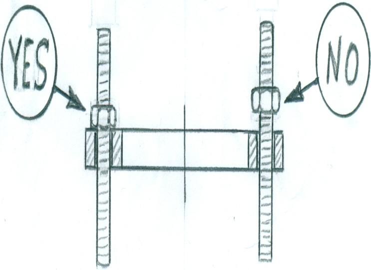
1) INTRODUZIONE - INTRODUCTION:
   Grazie per aver scelto un’elica a pale orientabili MAX PROP® EASY. Questo libretto di istruzioni servirà
   a rispondere a tutte le Vostre domande sul montaggio e sull’uso dell’elica. Vi consigliamo di leggerlo
   attentamente e di fare la verifica del corretto funzionamento dell’elica prima di montarla sulla Vostra
   imbarcazione.
   Thank you for having chosen a MAX PROP® EASY automatic feathering propeller for your vessel.
   This instruction booklet is designed to answer to all your questions on assembly and use of the propeller.
   Please read it carefully and verify the correct working of the propeller before installing it on your boat.

2) REGOLAZIONE DEL PASSO - PITCH ADJUSTMENT:
   Il passo della MAX PROP® EASY dipende dal diametro dell’elica e dall’angolo α di inclinazione delle
   pale. Nella tabella di Fig.1 sono riportati per alcuni diametri, i passi in millimetri corrispondenti alle
   diverse angolazioni delle pale.
   The pitch on a MAX PROP® EASY changes according to the diameter of the propeller and the blades
   rotation angle α. Fig. 1 shows the pitches in millimeters corresponding to the degree of blades angle for a
   given propeller diameter.

                                                                                       Diametro dell’Elica (millimetri) – Propeller Diameter (millimeters)
                                                                               300   350     400      450     500      550      600      650      700        750   800
     α Angolo di imnclinazione pale (gradi) – Blades inclination angle

                                                                         10°   100   115     130      150     170      185      200      215      230        250   265

                                                                         12°   120   140     160      180     200      220      240      260      280        300   320

                                                                         14°   140   165     190      210     235      260      280      305      330        350   375

                                                                         16°   160   190     215      245     270      300      325      350      380        405   430

                                                                         18°   180   215     245      275     305      335      365      400      430        460   490

                                                                         20°   205   240     275      310     345      375      410      445      480        515   550

                                                                         22°   230   265     305      340     380      420      455      495      535        570   610

                                                                         24°   250   295     335      375     420      460      505      454      585        630   670

                                                                         26°   275   320     370      415     460      505      550      590      645        690   735

                                                                         28°   300   350     400      450     500      550      600      650      700        750   800

                                                                         30°   325   380     435      490     545      600      655      705      760        815   870

                                                                                                             Fig. 1

    Il diametro ed il passo devono essere calcolati come se la MAX PROP® EASY fosse una normale elica
    fissa. La MAX PROP® EASY offre in più rispetto alle eliche tradizionali, il vantaggio di permettere una
    ottimizzazione del passo qualora i risultati non fossero completamente soddisfacenti.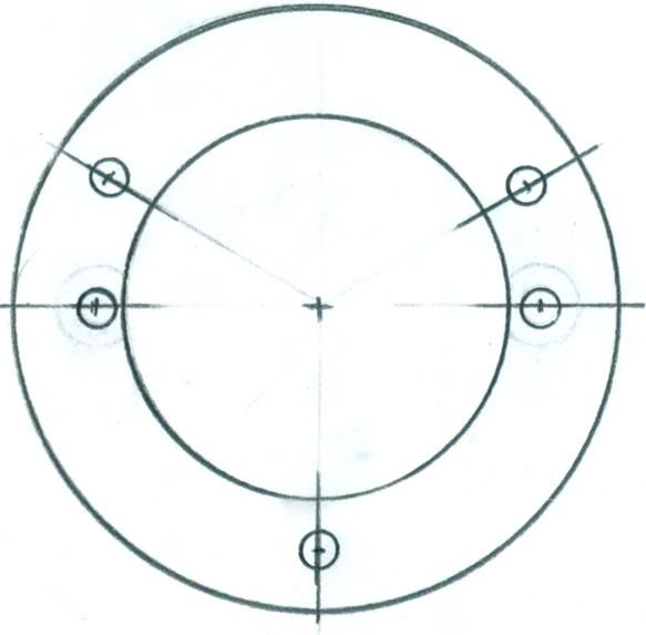
Se il motore raggiunge con difficoltà il numero di giri di regime, occorre diminuire l’angolo α di
inclinazione delle pale, se al contrario supera il numero di giri di regime, occorre aumentare l’angolo α.
Variando l’angolo di 2 gradi, la velocità dell’imbarcazione varia di circa il 14%, a pari numero di giri del
motore, oppure il numero di giri del motore varia di circa il 14%, a pari velocità dell’imbarcazione.

 Diameter and pitch must be calculated as if MAX PROP® EASY were a normal fixed propeller. MAX
 PROP® EASY then offers the great advantage of pitch adjustability in order to better optimize the
 performance of the propeller. If the engine does not reach the desired RPM, reduce the blade angle α ;
 on the contrary, if the engine exceeds the desired RPM, increase the blade angle α. Whit a 2 degrees
 variation of the blade angle, the speed of the vessel varies 14% at the same RPM or the RPM varies
 14% at the same speed of the vessel.

PER VARIARE IL PASSO PROCEDERE COME SEGUE FACENDO RIFERIMENTO ALLE FIG.1 E 2

                                                Fig. 2

   a) Nella fig. 1 sono indicati i passi dell’elica in millimetri corrispondenti ai vari angoli in gradi di
      inclinazione delle pale e ai vari diametri delle eliche.

   b) Nel corpo di ogni elica sono praticati due fori filettati, contrassegnati con le lettere “R” e “L”, entro
      i quali sono alloggiate due aste(viti);

   c) Il passo dell’elica sia in marcia avanti che in marcia indietro viene facilmente variato sostituendo
      le aste (viti) montate sul corpo dell’elica con altre aste (viti) aventi lunghezze diverse. Il passo in
      marcia avanti varia sostituendo l’asta alloggiata nel foro “R” se l’elica è destrorsa oppure sostituendo
      l’asta alloggiata nel foro “L” se l’elica è sinistrorsa.

   d) Nella fig. 3 è indicato l’elenco delle aste (viti) di regolazione del passo che vengono date in
      dotazione ad ogni elica EASY.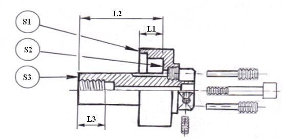
e) Inserendo nei fori filettati del corpo elica rispettivamente le aste (viti) 20 e 2, le pale
assumono un’inclinazione di 20 gradi, sia in marcia avanti che in marcia indietro;Variando di 1mm la
lunghezza del gambo delle aste (viti), l’inclinazione delle pale varia di 2 gradi;
f) Per ogni singola elica:
l’asta (vite) 20 ha la medesima lunghezza dell’asta (vite) 2
l’asta (vite) 16 ha la medesima lunghezza dell’asta (vite) 3
l’asta (vite) 24 ha la medesima lunghezza dell’asta (vite) 1
PROCEED AS FOLLOWS IN ORDER TO CHANGE THE PITCH, WITH REFERENCE TO FIG. 1 AND 2
a) Pitches of the propeller corresponding to blades inclination and propeller diameter are shown in
millimeter in fig. 1
b) In the body of every propeller are opened two threaded bores, marked with letters “R” and “L”;
within these bores are placed two poles (screws).
c) The pitch of the propeller, both in front and reverse position, can be easily varied changing poles
(screws) assembled on the body of the propeller with other poles (screws) having a different length.
The pitch in front position varies changing the pole (screw) placed in bore “R” if the propeller is
right-handed or changing the pole (screw) placed in bore “L” if the propeller is left-handed.
d) The list of the pitch regulation poles, that are supplied with every EASY propeller is indicated in fig.
3
e) Inserting in the threaded bores opened in the body of the propeller the poles (screws) 20 and 2, the
blades assume a 20 degrees inclination, both in front position and reverse position. Varying 1
millimeter the length of the poles (screws), blades inclination has a 2 degrees variation
f) In every single propeller:
pole (screw) 20 has the same length as pole (screw) 2
pole (screw) 16 has the same length as pole (screw) 3
pole (screw) 24 has the same length as pole (screw) 1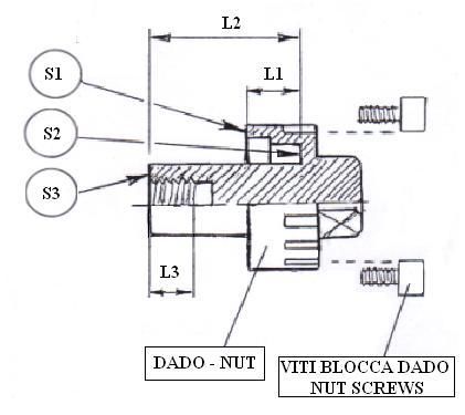
ELENCO DELLE ASTE (VITI) DI REGOLAZIONE DEL PASSO CHE VENGONO DATE IN
     DOTAZIONE AD OGNI ELICA "EASY"

     LIST OF THE PITCH REGULATION POLES (SCREWS) THAT ARE SUPPLIED WITH EVERY
     "EASY" PROPELLER

                                 ELICA DESTRORSA                         ELICA SINISTRORA
                                 RIGHT ROTATION                           LEFT ROTATION
INCLINAZIONE PALE
      (GRADI)
BLADES INCLINATION     MARCIA AVANTI      MARCIA INDIETRO      MARCIA AVANTI      MARCIA INDIETRO
    (DEGREES)            FORO “R”             FORO “L”           FORO “L”             FORO “R”
                     FORWARD POSITION     REVERSE POSITION   FORWARD POSITION     REVERSE POSITION
                         BORE “R”             BORE “L”           BORE “L”             BORE “R”

        16                  16                     1                16                      1

        18                  18                                      18

        20                  20                     2                20                      2

        22                  22                                      22

        24                  24                     3                24                      3

                                               Fig. 3
3) ISTRUZIONI PER CAMBIARE IL SENSO DI ROTAZIONE DELL’ELICA MAX PROP FAST -
INSTRUCTIONS TO CHANGE PROPELLER ROTATION:
La MAX PROP® EASY offre la possibilità di modificare il senso di rotazione, per es. in caso di cambio del
motore, o di semplice errore al momento dell’ordine.
(Se aveste dei dubbi: per capire il senso di rotazione del Vostro asse motore, è necessario innestare la marcia
avanti e guardare da poppa verso prua. Se l’asse gira in senso orario la rotazione è destrorsa, al contrario se gira
in senso antiorario la rotazione è sinistrorsa). Per cambiare il senso di rotazione della MAX PROP® EASY, da
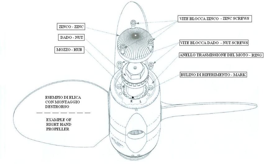
destrorsa a sinistrorsa o viceversa, procedere come segue, facendo riferimento alla fig.4:
Svitare le viti blocca - zinco e rimuovere lo zinco
Svitate le viti blocca - dado e rimuovete il dado (noterete che sulla parte finale poppiera del mozzo vi è
un anello di sicurezza seeger che dovrete sfilare).
Sfilare l’anello di trasmissione moto sul quale viene fissato lo zinco (anello porta-zinco),
Una volta sfilato l’anello porta-zinco, vedete che un dente del mozzo (lato verso poppa) è
contrassegnato con un bulino e che due denti dell’anello porta-zinco sono contrassegnati rispettivamente
con la lettera “L” (left) ed “R” (right).
Se rimontate l’anello porta-zinco con il dente “R” in corrispondenza del dente del mozzo che ha
stampigliato il bulino avrete un elica destrorsa, se invece inserite l’anello con il dente “L” in
corrispondenza del dente del mozzo che ha stampigliato il bulino avrete un elica sinistrorsa(vedi Fig.4).
Inserite il seeger nella sua sede
Avvitate il dado bloccandolo con le viti blocca – dado
Rimettete lo zinco fissandolo con le tre apposite viti
With the MAX PROP EASY® it is also possible to change the rotation, e.g. if you change the engine, or if there
was a mistake when ordering the prop. If you have doubts about the engine rotation, it can be determined
looking forward from the stern of the boat. With the engine in forward position a clockwise rotation of the
propeller means it is right handed(R), and a counter-clockwise rotation is left handed (L).
In order to change the rotation of the MAX PROP EASY®, from a right hand rotation to a left hand rotation or
vice versa do as follows, referring to fig.4
Unscrew the locking-zinc screws, and remove the zinc
Unscrew the locking-nut screws and remove the nut ( note that on the aft edge of the hub there is a
security ring “seeger” that must be slipped off )
Release the zinc-bearing ring
Once released the zinc-bearing ring, you see that on one tooth of the hub (the aft side)there is a
reference mark, and two teeth of the bearing-zinc ring are marked one with “L” and the other with “R”.
If you place the zinc bearing ring in its seat again, matching the “L” tooth with the hub reference mark,
you have a left hand rotating propeller, on the contrary, with the “R” tooth you have a right rotating
propeller as in fig.4
Place the “seeger” ring in its seat
Tighten the nut and secure it with the locking-nut screws
Place the zinc again, and secure it with the 3 proper screwsFig. 4
4) MONTAGGIO - ASSEMBLY:
Effettuate le varie operazioni facendo riferimento alla Fig.5. L’elica è fornita già assemblata come destrorsa
o sinistrorsa secondo l’informazione ricevuta al momento dell’ordine,e con un determinato passo
richiesto,così che possa essere montata direttamente sull’albero motore. Tenete presente che le parti che
compongono la MAX PROP® EASY non sono intercambiabili. Nel caso si ricevessero
contemporaneamente più eliche, sarà quindi necessario fare molta attenzione a non mischiare i pezzi
smontati.
Please, do as follows with reference to Fig. 5. The propeller is supplied already assembled for right or left
rotation, according to the information received with the order and with the pitch required, so that it can
directly fit on the shaft.
MAX PROP® EASY parts are NOT interchangeable. Please, make sure , if you receive more than one
propeller, that you do not interchange parts..Fig. 5
a) Inserite l’elica già assemblata sull’asse motore, come fosse un’elica fissa, verificate che la linguetta
sia di misura appropriata: che abbia gioco sulla faccia superiore per evitare di portare l’elica fuori
centro, ma senza gioco tra le superfici laterali .
Fit the already assembled propeller to the shaft, as if it was a fixed propeller, and make sure that the
key has proper dimension: a good key has almost no clearance side to side but a very small clearance
on its upper surface. This clearance is to avoid the propeller to be pushed out of center by a key which
is too tall.
b) Stringere il dado e bloccarlo mediante le due viti blocca - dado che si situano nelle apposite sedi
Tighten the nut and secure it in place using the two allen head screws.
c) Riempite l’elica con grasso marino attraverso gli appositi fori usando un ingrassatore. L’elica MAX
PROP® EASY funziona in modo corretto solo se totalmente riempita di grasso fluido. Verificare che
il grasso trafili dalle giunture rotanti tra il corpo centrale, il mozzo e le pale, in modo da essere sicuri
che tutte le superfici rotanti siano lubrificate perfettamente. Il grasso deve essere fluido per
garantire che continuerà ad uscire tra le superfici anche dopo anni di funzionamento.
Fill the prop with marine grease (supplied) using the grease fitting (supplied) inserted into the
grease holes marked “grease” . The MAX PROP® EASY propeller works properly only if the
central body is completely filled with the correct grease. Verify that the grease is oozing from the
rotating joints between the central part and the hub , so that all of the moving surfaces are
perfectlyoiled. The grease used must be a type of grease approved by MAX PROP® so it will remain
fluid after years of use and will not get too stiff in cold water.
d) Orientate le pale nella loro posizione di bandiera (cioè perfettamente allineate con l’asse del corpo
dell’elica), facendo attenzione che il loro profilo sia come quello mostrato in Fig.6.
Move the blades into the feathered position, making sure that the rounded trailing edges of
the blades are aft as shown in Fig. 6 .Fig.6
e) Prima di varare la barca è indispensabile effettuare le seguenti operazioni:
Bloccare l’albero motore.
Verificare che le pale dell’elica ruotino liberamente dalla posizione di marcia
avanti a quella di marcia indietro con la semplice spinta delle mani; a fine corsa il
loro angolo di inclinazione deve essere quello prescelto.
In posizione di bandiera le pale devono essere perfettamente allineate ed orientate
come in Fig. 6
Verificare che l’elica sia piena di grasso marino fluido
Assicurare la protezione dell’elica contro la corrosione galvanica applicando gli
apposite anodi di zinco sull’elica e sull’asse motore.
Before launching the boat, it is absolutely necessary to operate as follows:
Hold the propeller shaft.
Check that the blades of the propeller rotate freely from the forward to the reverse
position just by a light effort
In the feathered position the blades must be perfectly lined up and set like Fig. 6
Check that the propeller body is full of fluid marine grease
Make sure that the propeller is protected from galvanic corrosion by using the usual
zinc anodes on the propeller and the shaft5) USO DELL’ELICA - PROPELLER USE:
L’elica MAX PROP® EASY funziona in modo completamente automatico. Prende il passo quando si fa
ruotare l’asse motore a marcia avanti e a marcia indietro (ATTENZIONE: è decisamente
sconsigliabile l’inversione di marcia ad un numero di giri troppo elevato). L’elica va in bandiera a
motore spento partendo dalla posizione di marcia avanti, ad asse bloccato. Per far disporre l’elica in
bandiera operare nel seguente modo:
Spingere la barca ad una velocità di almeno 2-3 nodi in marcia avanti
Spegnere il motore senza disinnestare la marcia avanti , e bloccare l’asse motore.
NON spegnete però il motore in marcia indietro, perchè in questo caso le pale saranno nella posizione
di marcia indietro e non andranno in bandiera. Si potrebbe infatti usare questo sistema per muovere l’asse
quando è collegato ad un alternatore.
Se il cinematismo di trasmissione del moto è dotato di invertitore idraulico, l’albero motore può essere
bloccato in modo automatico montando l’apposito freno che può essere fornito da MAX PROP® con un
supplemento di costo.
The MAX PROP® EASY works automatically. By putting the engine in gear the blades will engage in
either forward or reverse (WARNING : do not change from forward to reverse and vice versa when the
engine is running at high RPM) and feathers from forward position when you turn of the engine and block
the shaft. The best way to feather the propeller is:
Power at 2 to 3 knots in forward
Turn off the engine while still engaged in
forward.
If your propeller has been greased properly it will feather in a fraction of a second as soon as you stop
the shaft from freewheeling. DO NOT kill the engine while in reverse. In this case the blades will be in
the reverse position and will not feather. You can actually use this feature to drive a shaft alternator.
Modern engine transmission are either mechanical or hydraulic. With a mechanical transmission, the
best way to stop the shaft freewheeling is to engage the transmission in reverse ( WARNING : engage
the reverse only after the engine has stopped completely).With a hydraulic transmission you must shut
off the engine while still engaged in forward. The remaining hydraulic pressure will en effect lock the
shaft for a few moments, enough for the MAX PROP® to feather.
If the moving transmission kinematic is provided with an hydraulic inverter, the motor shaft can get
automatically stopped assembling the brake supplied by MAX PROP® with an extra charge
.
6) AVVERTENZE IMPORTANTI - WARNING:
Seguire con attenzione le istruzioni qui sotto riportate allo scopo di evitare danneggiamenti all’elica:
Prima di ogni inversione di marcia lasciare che il numero di giri del motore diminuisca, e poi invertire.
Verificare che il corpo dell’elica sia pieno di grasso molto fluido. La mancanza di grasso lubrificante
causa una rotazione delle pale a scatti che produce urti irregolari che possono danneggiare le dentature
delle pale stesse e dell’ingranaggio centrale.
Proteggere l’elica contro la corrosione galvanica mediante l’applicazione di una sufficiente massa di
zinco sull’albero motore. Sostituire ogni anno gli anodi di zinco anche se questi non si sono corrosi e
verificare che ci sia un buon contatto elettrico tra lo zinco, l’elica e l’asse (le superfici di contattodevono essere pulite con della tela abrasiva).
In order to avoid a shock to the gears on the blades and cone gear, that could be damaging the teet,. it is
important to follow the instructions below carefully,
When going from forward to reverse and the opposite, it is necessary to idle down and shift at low
RPM’s between gears
The propeller must always be completely filled with a recommended grease.
Make sure that you always keep the zinc anodes in good condition. They must be replaced at least once
a year, even if they still look ok. The propeller must be protected by a lot of zinc, so also use a zinc on
the shaft when possible. When replacing it make sure that you clean the contact point between the zinc
and the propeller shaft in order to have a good electrical contact.
7) SMONTAGGIO DELL’ELICA - PROPELLER REMOVAL:
Per smontare l’elica si deve togliere lo zinco e le viti ferma dado; fissare poi sull’anello porta-zinco
mediante cinque viti una rondella forata (fig.7). Avvitare le cinque viti (sufficientemente lunghe e dotate di
cinque dadi) nei cinque fori filettati praticati nell’anello porta zinco, facendo attenzione che tutte le cinque
viti siano avvitate fino al fondo del proprio foro filettato. Fare quindi appoggiare tutti e cinque i da di sul
disco forato che funge da estrattore (vedi fig. 7). Cominciare a svitare in maniera molto delicata il dado
blocca – elica, che andrà a premere contro la rondella (fig. 7) e verificare che tutte le cinque viti di
estrazione collaborino con il medesimo carico alla estrazione dell’elica. Continuare a svitare il dado
lentamente, facendo attenzione a non caricare troppo le viti per evitare la rottura delle stesse.
In order to remove the propeller you must first remove the zinc and unscrew the nut , then pull off the prop
using MAX PROP® extractor, or a similar tool with external threading, as per fig 7. Tighten the five
screws (that must be long enough and provided with 5 nuts) in the five threaded bores made in the zinc,
being careful that all the five screws are well tighten until the end of their threaded bores. Make the five
nuts lean against the pierced disc that serve as extractor. (see fig. 7). Start unscrewing very gently the
locking nut, that in this way will push against the MAX PROP® extractor and verify whether all the five
extracting screws work together with the same load while extracting the prop. Go on unscrewing the nut
slowly, being careful not to load the screws too much, in order to avoid them to brake.
Fig.78) ISTRUZIONI PER LA CORRETTA LAVORAZIONE DEL DADO DI FISSAGGIO
DELL’ELICA Fig. 8. - INSTRUCTIONS FOR THE PROPER WORKING OF THE BLOCKING
NUT OF THE PROPELLER Fig. 8.
a) Quando viene serrato sull’albero motore, il dado deve appoggiare sulle tre superfici S1, S2, S3.
Pertanto, quando si lavora il dado occorre fare attenzione che le lunghezze L1 e L2 coincidano
perfettamente con le corrispondenti lunghezze rilevate sul mozzo dell’elica, e che la lunghezza L3 sia
maggiore della lunghezza della parte finale filettata dell’albero motore. Per verificare la corretta
esecuzione del lavoro è sufficiente, dopo aver ultimato la lavorazione del dado, spalmare un
leggerissimo strato di blu di Prussia sulle tre superfici S1, S2, S3. Inserire quindi il dado nel proprio
alloggiamento ricavato nel mozzo e farlo ruotare delicatamente rispetto al mozzo, esercitando una
leggera pressione. Ad operazione ultimata, le tre superfici del mozzo dovranno risultare colorate di
blu.
When it’s locked on the motor shaft, the nut must contact the 3 surfaces S1,S2,S3. Therefore, when you
work the nut you must be sure that length L1 and L2 coincide precisely with the corresponding lengths
of prop hub, and that length L3 is greater than the length of the threaded edge of motor shaft To
check that the work is done properly, you just have to spread a very thin coat of Prussian blue on the 3
surfaces S1,S2,S3. Insert then the nut in its seat in the hub and let the nut rotate softly in relation to the
hub, with a light pressure. When this is done, the 3 surfaces of the hub must be painted in blue.
b) Quando si monta l’elica sull’albero motore occorre verificare che la parte filettata dell’albero non
arrivi a toccare il fondo filettato del dado, e che, serrando il dado, la rotazione delle pale attorno ai
propri assi non diventi dura. Nel caso in cui il movimento di rotazione delle pale diventasse duro,
occorre asportare dalla superficie S1 una piccolissima quantità di materiale. Detta asportazione può
essere fatta usando semplicemente una lima piatta a grana fine oppure della tela smeriglio.
When fitting the prop on the motor shaft, it’s necessary to check that the threaded part of the motor
shaft doesn’t touch the threaded end of the nut. Also, when the nut is tight, the blades rotation on their
axis does not get hard. In case the blades rotation movement becomes hard, you have to remove from
surface S1 a very small amount of material. This operation can be done simply by using a flat smooth
file.
Fig. 89) DADO SPECIALE (FIG. 9) DA USARE PER IL FISSAGGIO DELLE SOLE ELICHE DOTATE
DI DISPOSITIVO ANTISHOCK - SPECIAL NUT (FIG.9) ONLY FOR MAX PROP WITH ANTI-
SHOCK DEVICE
A differenza del dado standard,questo tipo di dado, quando viene serrato sull’albero motore, deve
appoggiare esclusivamente sulle due superfici S1 e S2, e viene bloccato mediante 4 elementi: due spine
filettate, più una vite centrale fissata con un grano. Quando si monta l’elica occorre effettuare le stesse
verifiche descritte per il dado di fig. 8
Unlike the standard nut, this kind of nut, when it’s locked on the motor shaft, must lean ONLY to surfaces
S1 and S2 and is secured by 4 devices: 2 threaded pins, and a central screw with a dowel. When you mount
the propeller on the motor shaft the same nut checking is necessary as previously described for fig. 7
Fig. 9CONDIZIONI GENERALI DI VENDITA DELLE ELICHE MAX PROP
1) La Max Prop Srl produce le proprie eliche su misura, espressamente secondo le richieste del cliente.
2) La Max Prop Srl garantisce che ogni elica di propria produzione viene collaudata e lascia la fabbrica in
perfette condizioni di funzionamento.
3) La Max Prop Srl si impegna a riparare o sostituire gratuitamente i pezzi originali dell'elica che risultassero
eventualmente danneggiati per difetti di fabbricazione o di materiale. Non corrisponderà, per
nessun motivo, alcun risarcimento e/o rimborso, neppure parziale. La garanzia offerta dalla Max Prop Srl
si limita
4) pertanto esclusivamente alla riparazione o sostituzione gratuita dell'eventuale elica difett osa e
non comprende alcun eventuale danno, risarcimento o rivendicazione di qualsiasi natura.
5) Le eventuali riparazioni in garanzia saranno effettuate esclusivamente dalla Max Prop srl presso la
propria
6) officina sita in Milano- Via Galliari 1. Il cliente provvederà a fare pervenire presso tale officina i pezzi
difettosi a proprie spese e a propria cura.
7) La suddetta garanzia è valida per 12 mesi a partire dalla data della consegna dell’elica.
8) L’acquirente prende atto che il prezzo di vendita dell’elica è stato stabilito in considerazione della
accettazione da parte sua delle presenti condizioni generali di vendita. Con tale accettazione l’acquirente
esclude, come indicato al punto 3, qualsiasi tipo di rivendicazione.
9) Per ogni eventuale controversia rimane stabilito che il foro competente sarà quello di Milano.
10) Le presenti condizioni di vendita sono parte integrante di ogni contratto di acquisto stipulato con Max
Prop Srl.
GENERAL SALE CONDITIONS
1) Max Prop Srl produces her own propellers to measures, expressly as the customer requires
2) Max Prop grants that every propeller produced is tested and leaves the workshop in perfect functioning
conditions
.
3) Max Prop Srl. is willing to repair and replace free of charge, the original pieces of the propeller which
may result damaged due to construction defects or due to material defects. Max Prop will not pay, for any
reasons any refund whatsoever , not even partial. The warranty granted by MAX PROP Srl. is therefore
limited exclusively to the repair or replacement of any possible defective propeller and does not include
any damage compensation refund, or claim of any kind.
3) The reparations in warranty that might be needed will be carried on exclusively by MAX PROP at its own
workshop in Italy - Milan – Via Bernardino Galliari, 1. The customer will, at his own charge and care,
send the defective pieces to MAX PROP’s workshop.
4) This warranty is valid 12 months starting from the date of propeller delivery.
5) The customer confirms that the purchase price of the propeller has been established considering his
acceptance of the present general conditions of sale. With this acceptance the customer excludes, any type
of claim as advised in point n° 3.
6) Any possible controversy will fall within the jurisdiction of the Milan Courts-Italy
7) These conditions of sale are integral part of any purchase contract agreed with MAX PROP Srl.Prodotta da / Manufactured by :
MAX PROP PATENTED PROPELLERS
MAX PROP SRL – Via Bernardino Galliari, 1 – 20156 MILANO
Tel. +39.02.33.40.43.25 - Fax +39.02.47.92.13.06 – www.maxprop.itPuoi anche leggere