LL AA BBDDMMMM2 Manometro digitale professionale per misure di PRESSIONE e TEMPERATURA - Bart Manometri
←
→
Trascrizione del contenuto della pagina
Se il tuo browser non visualizza correttamente la pagina, ti preghiamo di leggere il contenuto della pagina quaggiù
LABDMM2
                   MANUALE OPERATIVO
                      MO.LABDMM2.560.R0

    Manometro digitale professionale
per misure di PRESSIONE e TEMPERATURA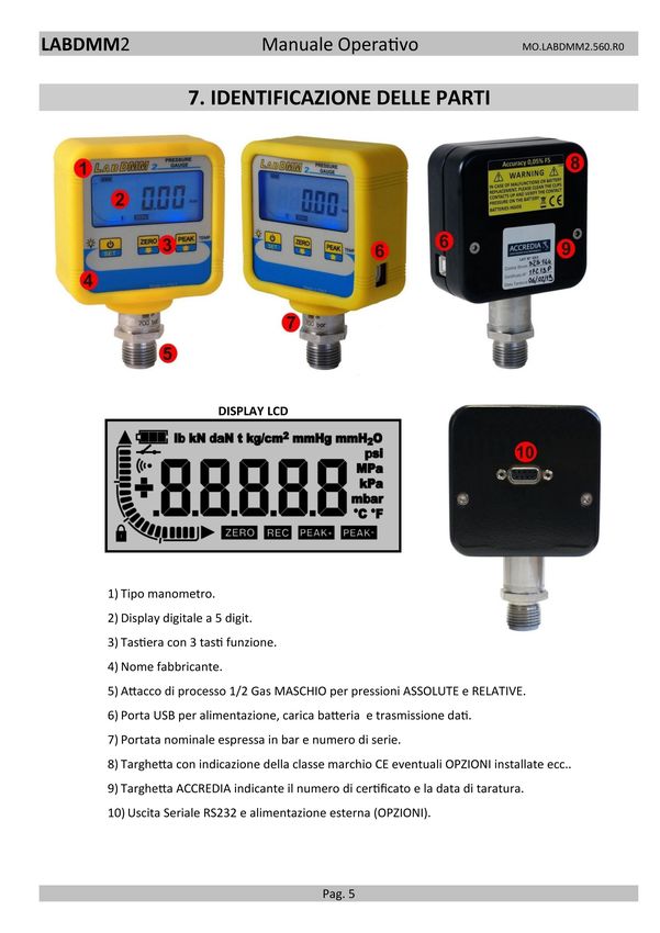
LABDMM2                                    Manuale Operativo                                      MO.LABDMM2.560.R0

                                                     INDICE
                      1. DICHIARAZIONE DI CONFORMITÀ                                         2
                      2. IDENTIFICAZIONE DEL PRODOTTO                                        3
                      3. USI NON PREVISTI                                                    3
                      4. SMALTIMENTO                                                         3
                      5. TRASPORTO                                                           3
                      6. INTRODUZIONE E CAMPO DI IMPIEGO                                     4
                      7. IDENTIFICAZIONI DELLE PARTI                                         5
                      8. DATI TECNICI                                                        6
                      9. OPZIONI                                                             7
                      10. ACCESSORI                                                          8
                      11. INDICAZIONI STANDARD                                               9
                      12. CODICI DI ACQUISTO                                                 10
                      13. AVVERTENZE SULLA SICUREZZA                                         10
                      14. INSTALLAZIONE                                                      11
                      15. ACCENSIONE E SPEGNIMENTO                                           11
                      16. MESSAGGI DI ERRORE                                                 11
                      17. DESCRIZIONE DEI TASTI                                              12
                      18. FUNZIONE DI PICCO                                                  12
                      19. MENU DI CONFIGURAZIONE                                             13
                      20. DATA LOGGER                                                        14
                      21. PROGRAMMAZIONE DATA LOGGER                                         14
                      22. IMPOSTAZIONE DATA E ORA                                            14
                      23. FUNZIONAMENTO DATA LOGGER                                          15
                      24. FUNZIONE BLOCCO TASTI                                              17
                      25. UNITÀ DI MISURA DELLA TEMPERATURA                                  17
                      26. RICARICA BATTERIA E SOSTITUZIONE                                   18
                      27. TRASMISSIONE WIRELESS                                              19
                      28. CALIBRAZIONE PRESSIONE                                             20
                      29. CALIBRAZIONE TEMPERATURA                                           21
                      30. CALIBRAZIONE PRESSIONE ATMOSFERICA                                 22
                      31. PROTOCOLLO DI COMUNICAZIONE SERIALE USB/RS232                      23
                      32. COLLEGAMENTI ELETTRICI                                             24
                      33. DIMENSIONI                                                         26

La BART s.r.l. si riserva il diritto, qualora lo ritenesse necessario, di apportare modifiche di qualsiasi
genere senza alcun obbligo di preavviso.

I dati contenuti in questo manuale sono indicativi, la ditta declina ogni responsabilità per errori o
discordanze dal presente manuale.

                Nel seguito del manuale sono identificate le operazioni delicate e le possibili fonti di rischio
                per l’utente o per lo strumento con il seguente simbolo.

                                                        Pag. 1
LABDMM2                                  Manuale Operativo                               MO.LABDMM2.560.R0

                        1. DICHIARAZIONE DI CONFORMITÀ

                                   DICHIARA CHE IL SEGUENTE PRODOTTO
Nome del prodotto: LABDMM2
Tipo: MANOMETRO DIGITALE
Anno di costruzione: 2019
Opzioni: questa dichiarazione copre tutte le opzioni specificate nel Data Sheet e nel Manuale.
                                 È CONFORME ALLE SEGUENTI DIRETTIVE
                 2014/30/UE - 2014/35/UE - 2011/65/UE(RoHS) - 2012/19/UE (RAEE/WEEE)
                                   È CONFORME ALLE SEGUENTI NORME
                                   EN 61010-1(2013) EN 61326-1 (2013)
                                      È CONFORME AL REGOLAMENTO
                                          n° 1907/2006 (REACH)
Il prodotto è stato provato nella configurazione tipica di installazione descritta nel manuale di istruzioni.
Il prodotto soddisfa i requisiti delle Norme citate, sulla base dei risultati delle prove e delle valutazioni
descritte nel Fascicolo Tecnico.
Io sottoscritto dichiaro che il prodotto sopra descritto soddisfa i requisiti delle Direttive, delle Norme e dei
Regolamenti sopra citati.

                                                    Pag. 2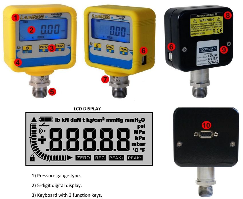
LABDMM2 Manuale Operativo MO.LABDMM2.560.R0
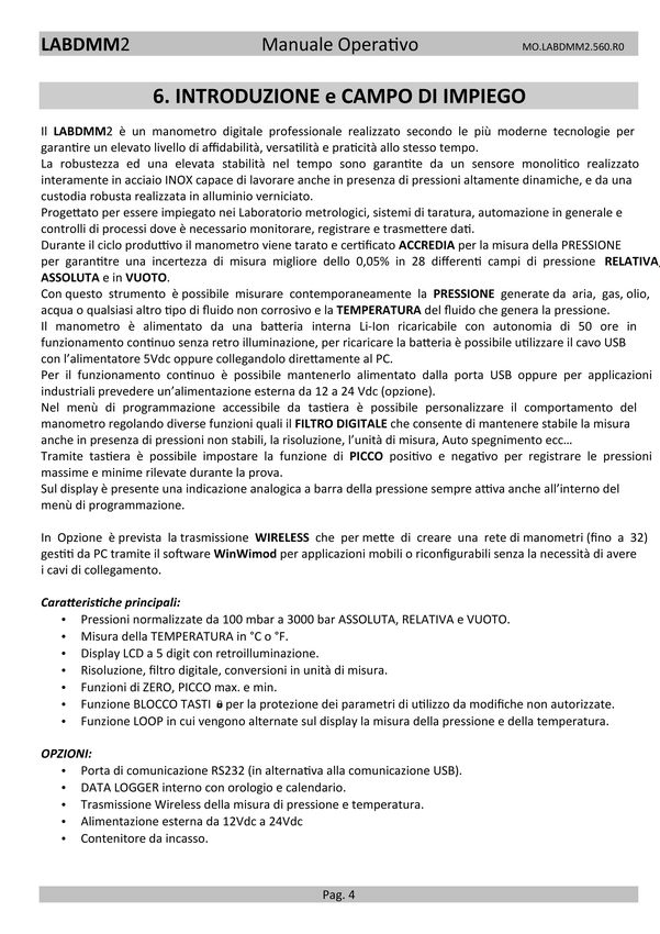
2. IDENTIFICAZIONE DEL PRODOTTO
L’identificazione avviene con il nome del prodotto e del costruttore sul pannello frontale dello strumento.
La portata nominale e il numero di serie è marcato al LASER sul corpo del sensore.
Sulla targhetta adesiva posteriore sono indicate alcune caratteristiche tecniche, il marchio CE, il simbolo dello
smaltimento e le opzioni installate.
3. USI NON PREVISTI
Ambienti con atmosfera esplosiva.
Ambienti con gas infiammabili o corrosivi.
4. SMALTIMENTO
Lo strumento è una apparecchiatura professionale conforme alle Direttive 2011/65/UE (RoHS)
e 2012/19/UE (RAEE).
L’apparecchiatura deve essere avvolta in imballo plastico o di cartone e consegnata a ditte
specializzate nello smaltimento di rifiuti elettrici ed elettronici secondo le leggi del paese dove
lo strumento è commercializzato.
5. TRASPORTO
La componentistica è elettronica.
In caso di trasporto imballare adeguatamente lo strumento.
Attenzione ai forti urti e all’umidità.
Si consiglia di utilizzare la valigetta che può essere acquistata separatamente, vedere capitolo accessori.
Pag. 3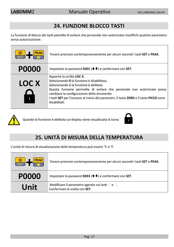
LABDMM2                              Manuale Operativo                               MO.LABDMM2.560.R0

   d) pressione altamente dinamica                                    75% F.S.
   ATTACCO DI PROCESSO                                            1/2" G Maschio
   GUARNIZIONE CONSIGLIATA                                         USIT A 63-18
   CHIAVE DI SERRAGGIO                                                 27 mm
   COPPIA DI SERRAGGIO                                                 28 Nm
   CLASSE PROTEZIONE (EN 60529)                                        IP40
   MATERIALE SENSORE                                               INOX 17-4 PH
   MATERIALE CONTENITORE                                            ALLUMINIO
                (1) Certificato ACCREDIA in modalità RELATIVA.
  (1)
                (2) In caso di non utilizzo o stoccaggio prolungato consigliamo di ricaricare la
                batteria almeno una volta al mese per evitare che la batteria possa scaricarsi
                completamente.

                         9. OPZIONI (da acquistare separatamente)
   DATALOGGER INTERNO                                          Pressione e Temperatura
   Orologio / calendario interno                                          SI
   Max punti memorizzabili                                     130.000 (solo pressione)
                                                           65.000 (pressione e temperatura)
   Frequenza di memorizzazione                                   Impostabile (Max 1s)
   Max Durata Data Logger (3)                                         10000 ore
   TRASMISSIONE WIRELESS                                              868 MHz
   DISTANZA MASSIMA                                              40 m in spazio libero
   MAX numero di manometri in rete                                        32
   USCITA SERIALE (4)                                                    RS232C
   BAUD RATE                                                       Fissa a 9600 baud
   TIPO DI TRASMISSIONE                                        a RICHIESTA o CONTINUA
   CONTENITORE DA INCASSO                               Contenitore per montaggio da pannello
   MATERIALE                                           Tecnopolimero rinforzato in fibra di vetro
   ALIMENTAZIONE ESTERNA (senza pila interna)                       da 12 a 24Vdc

                (3) Per lunghi tempi di durata del data logger può essere necessario alimentare
                esternamente il manometro o ricaricaricarlo periodicamente.

                (4) La comunicazione RS232C esclude la comunicazione USB, la porta USB viene
                uilizzata solo per ricaricare la batteria.

                                              Pag. 7
LABDMM2 Manuale Operativo MO.LABDMM2.560.R0
10. ACCESSORI
Accessori in dotazione:
Certificato ACCREDIA.
COVER in silicone resistente agli urti.
Alimentatore USB (5VDC @700mA)
Cavo USB.
VALIGETTA per il trasporto.
CD contenente MANUALE e DRIVER USB.
N° 2 coni mordente solo per i manometri ad
alta pressione da 1000 bar a 3000 bar.
Accessori: (da acquistare separatamente)
ALIMENTATORE ESTERNO da 220V a 12Vdc.
Codice: TALDMM
Cavo RS232 codice: TCAVOSERIALE
Quick analyzer
Quick analyzer Light
Software applicativi che si interfacciano
direttamente al manometro e supportano
l’operatore nelle diverse funzioni di test,
analisi, monitoraggio nel tempo, archiviazione
dati, gestione datat logger e trasferimento
delle misure su Microsoft Excel ecc…
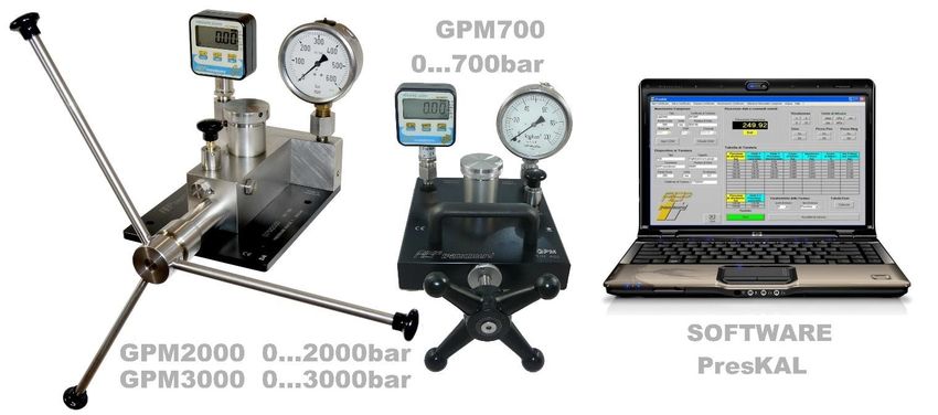
PresKAL
Software dedicato alla taratura e conferma
metrologica di misuratori di pressione come
manometri, trasduttori e trasmettitori di
pressione e pressostati.
Pag. 8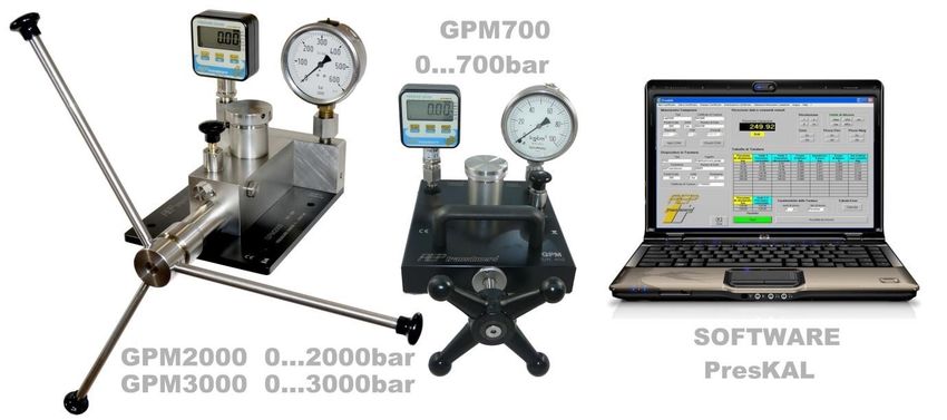
LABDMM2                                Manuale Operativo                              MO.LABDMM2.560.R0

Generatori manuali di pressione utilizzati per comparare le misure tra il manometro campione e lo strumento
in taratura.
Ideale per eseguire tarature e conferme metrologiche di misuratori di pressione come manometri, trasduttori
e trasmettitori di pressione e pressostati.

                                11. Indicazioni STANDARD
          Fondo
                   Display Risoluzione Display Risoluzione Display Risoluzione Display Risoluzione
           Scala
TIPO(1)     bar     bar         bar         mbar      mbar          psi        psi     MPa        MPa
  RV        0,1    0,1000     0,0001       100,00      0,01        1,450      0,002   0,0100     0,0001
  RV       0,25    0,2500     0,0001        250,00     0,05        3,620      0,002   0,0250     0,0001
  RV        0,5    0,5000     0,0001        500,00     0,05        7,200      0,002   0,0500     0,0001
 ARV        1,0    1,0000     0,0001       1000,0       0,1       14,500      0,002   0,1000     0,0001
 ARV        2,5    2,5000     0,0005       2500,0       0,5       36,200      0,005   0,2500     0,0001
 ARV         5     5,0000     0,0005       5000,0       0,5       72,500      0,010   0,5000     0,0001
 ARV         10    10,000      0,001        10000        1        145,00      0,02    1,0000     0,0001
  RV         20    20,000      0,002        20000        2        290,00      0,02    2,0000     0,0002
   R         50    50,000      0,005        50000        5        725,00      0,10    5,0000     0,0005
   R        100    100,00       0,01        99900       10        1450,0       0,2    10,000     0,001
   R        250    250,00       0,02        99900       20        3620,0       0,5    25,000     0,002
   R        350    350,00       0,05        99900       50        5000,0       0,5    35,000     0,005
   R        500    500,00       0,05        99900       50        7250,0       0,2    50,000     0,005
   R       700     700,00      0,05         99900       50        10000        0,2    70,000     0,005
   R      1000     1000,0       0,1         99000      100        14500         2     100,00      0,01
   R       1500    1500,0        0,2        99000      200        21700         5     150,00      0,02
   R       2000    2000,0        0,2        99000      200        29000         5     200,00      0,02
   R       2500    2500,0        0,2        99000      200        36250         5     250,00      0,02
   R       3000    3000,0        0,2        99000      200        43500         5     300,00      0,02
                                  (1) A = Assoluto R = Relativo   V = Vuoto

                                                   Pag. 9
LABDMM2 Manuale Operativo MO.LABDMM2.560.R0
12. Codifica di Acquisto
TLDMM Pressione CX41 Fondo scala OPZIONE
R = Relativa 0B1 5B 250B 1KB5 S = RS232C
A = Assoluta (2) 0B2 10B 350B 2KB W = WIRELESS
0B5 20B 500B 2KB5 (3)
1B 50B 700B 3KB (3)
2B5 100B 1KB
Esempio: T L D M M 2 R C X 4 1 5 0 B S
TDMMV Versione VUOTO relativo
(2)Certificato ACCREDIA in modalità RELATIVA.
La taratura ACCREDIA in modalità ASSOLUTA NON può essere eseguita dal Centro LAT N° 093, a richiesta può
essere commissionata ad altri Centri di taratura accreditati.
(3)
La taratura ACCREDIA NON può essere eseguita dal Centro LAT N° 093, a richiesta può essere
commissionata ad altri Centri di taratura accreditati.
13. AVVERTENZE SULLA SICUREZZA
L’installazione e la manutenzione del prodotto deve essere fatta solo da personale istruito e dopo aver letto
il presente manuale.
Dovranno inoltre essere rispettate tutte le norme di sicurezza previste dalla legislazione vigente nel paese
in cui verrà installato.
Il manometro non dovrà essere utilizzato per scopi diversi da quanto indicato nella sezione “Campo di
impiego” in caso contrario AEP transducers declina ogni responsabilità.
In particolare si evidenzia che il prodotto fornito non è un dispositivo di sicurezza.
Nella progettazione si sono prese tutte le precauzioni per minimizzare i rischi per la sicurezza
dell’utilizzatore, ma raccomanda ai responsabili dell’installazione l’analisi e la rimozione di eventuali rischi
residui.
Si ricorda che l’uso sicuro del prodotto richiede la sua completa integrità: per questo dovrà essere prestata
attenzione anche al trasporto e all’immagazzinamento.
Nel seguito del manuale sono identificate le operazioni delicate e/o le possibili fonti di
rischio per l’utente o l’apparecchiatura con il simbolo a fianco.
Pag. 10LABDMM2 Manuale Operativo MO.LABDMM2.560.R0
14. INSTALLAZIONE
Tenuta a O-RING USIT RING 12.70X18X1.5 Tenuta a CONO MORDENTE
per pressioni 1000 bar per pressioni 1000 bar per pressioni 1000 bar
O-RING tight for pressuresLABDMM2 Manuale Operativo MO.LABDMM2.560.R0
17. DESCRIZIONE DEI TASTI
Accensione dello strumento.
Premuto per 3 secondi accede al Menu dei parametri.
Premuto per circa 5 secondi spegne lo strumento.
Se abilitata, ad ogni pressione del tasto, viene attivata la retro illuminazione per il tempo
programmato nel menù
Durante la misura, se premuto per 3 sec., esegue lo ZERO del display, lo ZERO non ha
effetto sulla indicazione grafica a barra della pressione.
Durante la misura, premuto per 5 sec. disabilita la funzione di ZERO mostrando l’offset del
manometro.
In Modo Picco resetta il valore del Picco Misurato.
All’interno del menù dei parametri decrementa () il valore sul display.
Durante la misura, premuto per 2 sec., attiva la funzione di Picco+ (indica la pressione
maggiore rilevata dopo la sua attivazione).
Durante la misura, premuto per 4 sec., attiva la funzione di Picco- (indica la pressione
minore rilevata dopo la sua attivazione).
Durante la misura, premuto per 6 sec, visualizza la TEMPERATURA, per tornare alla
pressione premere nuovamente il tasto.
All’interno del menù dei parametri incrementa)
( il valore sul display.
18. FUNZIONE di PICCO
La funzione di PICCO viene utilizzata per
mantenere visualizzato sul display il valore di picchi
di pressione positivi o negativi.
Premendo il tasto PEAK si attiva la funzione.
La funziona si disattiva premendo nuovamente il
tasto PEAK, entrando nel Menù Principale o allo
spegnimento dello strumento.
I valori di PICCO possono essere azzerati
manualmente utilizzando il tasto ZERO.
Pag. 12LABDMM2 Manuale Operativo MO.LABDMM2.560.R0
19. MENU di CONFIGURAZIONE
Per entrare nel menù di configurazione mantenere premuto il tasto SET per circa 3 secondi, fino alla
comparsa della scritta Unit.
SELEZIONE UNITÀ DI MISURA
Unit In questo passo è possibile cambiare l’unità di misura.
Selezionare l’unità agendo sui tasti e .
Confermare con SET per passare al parametro successivo.
FILTRO DIGITALE
In questo passo è possibile variare l’effetto Filtro digitale agendo sui tasti e .
FL XX Aumentando il valore XX aumenta l’effetto di filtro, permettendo all’utente di
rilevare il valore medio di misure instabili o pulsanti.
I valori selezionabili sono da 0 a 5.
Confermare con SET per passare al parametro successivo.
RISOLUZIONE
In questo passo è possibile programmare la Risoluzione, agendo sui tasti e ,
r XX con cui lo strumento visualizza la pessione.
Valori selezionabili 1, 2, 5 e 10.
Modificare il parametro agendo sui tasti e .
Confermare con SET per passare al parametro successivo.
La funzione di LOOP permette di visualizzare sia la pressione che la temperatura.
Impostando 1 viene attivata la funzione di LOOP. Nella pagina di misura ogni 30
LOOPX secondi verranno visualizzati alternativamente la pressione e la temperatura
Impostando 0 la funzione viene disattivata
Modificare il parametro agendo sui tasti e .
Confermare con SET per passare al parametro successivo.
TEMPO DI AUTO SPEGNIMENTO
Definisce il numero di minuti (da 1 a 30) prima dello spegnimento automatico in
oFFXX caso di pressione costante. Il tempo di auto spegnimento entra in funzione se il
manometro non rileva variazioni di pressione maggiori del 10% della portata.
Modificare il parametro agendo sui tasti e .
Confermare con SET per passare al parametro successivo.
TRASMISSIONE SERIALE CONTINUA ON/OFF
cont0 : la trasmissione seriale della pressione viene ottenuta a richiesta
cont X cont1 : il valore di pressione viene trasmesso in modo continuo ogni 100ms
Modificare il parametro agendo sui tasti e .
Confermare con SET per passare al parametro successivo.
TEMPO DI ACCENSIONE DELLA RETROILLUMINAZIONE
Questo parametro definisce il tempo di accensione della retroilluminazione
Lt XX attivata con il tasto. Il tempo è impostabile tra 1s e 99s
Impostando 0 la retroilluminazione viene disattivata.
Attivando la retroilluminazione si avrà un maggiore consumo di batteria per cui
conviene disattivare la funzione quando non viene utilizzata.
ABILITAZIONE ALLA FUNZIONE DI ZERO (solo manometri assoluti)
Permette di abilitare/disabilitare la funzione di ZERO (nel caso di manometri
ZEroX assoluti).
Selezionare ZEro0 per disabilitare la funzione di ZERO (default)
Selezionare ZEro1 per abilitare la funzione di ZERO
Pag. 13LABDMM2 Manuale Operativo MO.LABDMM2.560.R0
20. DATA LOGGER (opzione)
Se è attiva l’opzione data logger nel menu si abilitano i seguenti parametri di configurazione.
21. PROGRAMMAZIONE del DATA LOGGER
Definisce il tempo tra 2 INTERVALLI DI ACQUISIZIONE.
t1 È possibile impostare: h = ore, mm = minuti, ss = secondi
h.mm.ss Esempio: 1.30.05 = 1 ora, 30 minuti e 5 seondi
Cambiando questo parametro verrà azzerato il log corrente.
Definisce il tempo globale di DURATA DEL CICLO.
t2 È possibile impostare: hhh = ore, mm = minuti
Esempio: 024.30 = 24 ore e 30 minuti.
hhh.mm Per tempi più lunghi di 1000 ore il formato di visualizzazione cambia mostrando
solo le ore permettendo di impostare tempi t2 fino a 10000 ore
Abilita / Disabilita la memorizzazione della temperatura.
t On Impostando tOFF è possibile registrare solo la PRESSIONE e memorizzare fino a
130.000 punti di misura.
t OFF Impostando tOn è possibile registrare sia la PRESSIONE che la TEMPERATURA e
memorizzare fino a 65.000 punti di misura.
22. IMPOSTAZIONE DATA e ORA
+ Tenere premuto contemporaneamente per alcuni secondi i tasti SET e PEAK.
P0000 Impostare la password 8321 () e confermare con SET.
Permette di impostare l’anno
d1 Modificare il parametro agendo sui tasti e .
Confermare con SET per passare al parametro successivo.
Permette di impostare il mese
d2 Modificare il parametro agendo sui tasti e .
Confermare con SET per passare al parametro successivo.
Permette di impostare il giorno
d3 Modificare il parametro agendo sui tasti e .
Confermare con SET per passare al parametro successivo.
Permette di impostare l’ora
d4 Modificare il parametro agendo sui tasti e .
Confermare con SET per passare al parametro successivo.
Permette di impostare i minuti
d5 Modificare il parametro agendo sui tasti e .
Confermare con SET per terminare l’impostazione della data e ora.
Se nessun parametro viene modificato la data/ora interna al manometro non viene modificata.
Durante l’aggiornamento della data/ora i secondi vengono impostati automaticamente a zero.
Pag. 14LABDMM2 Manuale Operativo MO.LABDMM2.560.R0
23. FUNZIONAMENTO del DATA LOGGER
Il DataLogger permette la memorizzazione di fino 130.000 (65.000 se viene memorizzata anche la
temperatura) punti di misura in step variabili da 1s a 10 ore in accordo al parametro t1 definito nel Menu di
configurazione. La durata del ciclo è stabilita dal parametro t2 definito sempre nel Menu di configurazione.
I dati memorizzati durante l’ultimo ciclo di DataLogging sono salvati in maniera permanente in memoria non
volatile all’interno del manometro per cui le misure saranno sempre accessibili fino alla creazione di un nuovo
ciclo di misura.
È possibile creare fino a 5 cicli parziali all’interno della memoria.
Ad ogni accettazione del comando per iniziare un ciclo verrà richiesto se si vuole iniziare un nuovo ciclo di
memorizzazioni (selezionare cont0) o continuare un ciclo precedente (selezionare cont1)
È essenziale comunque che tutti i cicli parziali siano realizzati con la stessa impostazione dei
parametri. In particolare lo stesso parametro t1 (intervallo di acquisizione) e abilitazione alla
memorizzazione della temperatura t on- t off.
Per cicli di Datalog molto lunghi è possibile risparmiare sul consumo di batteria utilizzando la funzionalità di
standy del manometro. Questa funzionalità si attiva automaticamente quando il tempo di acquisizione tra 2
punti di memorizzazione è maggiore del tempo di Auto Power Off.
Esempio:
Tempo di Auto Power Off : 1 minuto
Tempo di acquisizione (t1): 5 minuti
In queste condizioni nell’intervallo tra le due acquisizioni il manometro spegne il display e disattiva le altre
funzionalità. Si riattiva 30 secondi secondi prima di effettuare una misura e per i successivi 5 secondi.
In ogni caso durante un ciclo di datalog la funzione di autospegnimento del manometro non è attiva.
Se viene rilevato un livello di batteria eccessivamente basso il ciclo di datalog si interrompe
automaticamente. Tutti i dati memorizzati fino a quel momento sono salvati nella memoria interna.
Per cicli di datalog particolarmente lunghi la batteria interna al manometro non è sufficiente. È
necessario tenere alimentato il manometro esternamente attraverso la porta USB.
Nota: La funzionalità del DataLogger è pienamente gestibile da PC utilizzando il software Quick Analyzer
attraverso il quale è possibile:
• Visualizzare direttamente lo stato del ciclo in corso.
• Fare il download di tutte le misure effettuate.
• Salvare su un file tutte le misure effettuate.
• Visualizzare la curva di prova.
• Stampare la curva di prova.
• Esportare in Microsoft Excel la curva di prova.
• Fare lo START/STOP di un ciclo.
• Impostare i parametri t1 e t2 e temperatura ON/OFF.
Pag. 15LABDMM2 Manuale Operativo MO.LABDMM2.560.R0
Per una operatività locale e diretta sul manometro del datalogger operare come segue.
START CICLO Tenere premuto contemporaneamente, per alcuni secondi, i tasti e .
All’operatore viene richiesto se continuare un ciclo o iniziare un nuovo ciclo.
+ Sul display apparirà cont1 o cont0. Con i tasti e selezionare la scelta e premere
SET
La accettazione dello START verrà segnalata sul display dalla presenza della icona REC.
Ogni volta che verrà memorizzato un punto di misura lampeggerà per un secondo
l’icona
STOP CICLO Il ciclo si fermerà automaticamente al tempo impostato t2 oppure tenendo premuto
contemporaneamente, per alcuni secondi, i tasti e .
+ L’icona REC verrà spenta.
VISUALIZZAZIONE Tenere premuto contemporaneamente, per alcuni secondi, i tasti SET e .
DATI La accettazione della impostazione verrà visualizzata attraverso la visualizzazione delle
icone REC e lampeggianti.
+ È possibile visualizzare tutti i punti di misura utilizzando il tasto .
Per tornare indietro di un punto utilizzare il tasto .
Per uscire dalla funzione premere il tasto SET
Pag. 16LABDMM2 Manuale Operativo MO.LABDMM2.560.R0
26. RICARICA DELLA BATTERIA e SOSTITUZIONE
Il manometro è alimentato da 1 batteria Li-Ion RICARICABILE da 3.6V 1800mAh che garantisce una lunga
autonomia e un notevole numero di ricariche.
Il livello della batteria è segnalato da una icona con una indicazione dello stato di carica su 3 livelli.
Durante la fase di ricarica l’icona della batteria indicherà questo stato con la usuale indicazione variabile.
Il tempo di ricarica può durare fino a circa 8 ore. Quando la fase di ricarica sarà terminata verrà visualizzata
l’icona della batteria fissa.
BATTERIA COMPLETAMENTE SCARICA: Le misure effettuate in questo stato possono essere
alterate, pertanto è necessaria una ricarica immediata delle batterie.
BATTERIA COMPLETAMENTE CARICA.
Se dovesse rendersi necessario è possibile sostituire la batteria con una esattamente equivalente.
Richiedere la batteria di ricambio.
La sostituzione della batteria è molto semplice. È sufficiente rimuovere le 2 viti poste sul pannello posteriore,
rimuovere la batteria esausta ed inserire la nuova batteria collegando il connettore dedicato.
È possibile verificare la tensione in Volt della batteria nel seguente modo (si tenga presente che con batteria
completamente carica si avranno 4.2V mentre per batteria scarica si intende un valore al di sotto 3.5V):
+ Tenere premuto contemporaneamente per alcuni secondi i tasti SET e
PEAK.
P0000 Impostare la password 0055 () e confermare con SET.
3.723 Verrà visualizzato il valore in Volt del livello batteria.
Premere SET per uscire dalla funzione e ritornare alla misura di pressione
ATTENZIONE
In caso di non utilizzo o stoccaggio prolungato consigliamo di ricaricare la batteria almeno una
volta al mese per evitare che la batteria possa scaricarsi completamente.
Pag. 18LABDMM2 Manuale Operativo MO.LABDMM2.560.R0
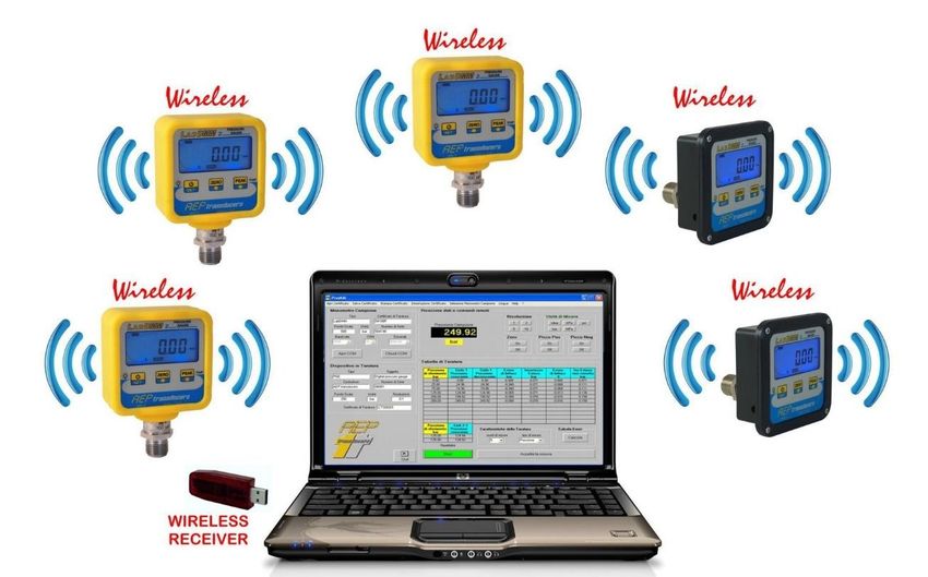
27. TRASMISSIONE WIRELESS (OPZIONE)
Il manometro LABDMM2 può trasmettere la misura di pressione e temperatura via radio ad intervalli regolari.
La frequenza di trasmissione, 868 MHz, rende la comunicazione sicura e affidabile anche in presenza di altri
sistemi di trasmissione come cellulari, walky talky, radio microfoni, telecomandi etc che normalmente
lavorano su altre frequenze.
È possibile creare una rete di max. 32 manometri radio gestibili attraverso il programma
WinWIMOD.
In questo ambiente è possibile creare e archiviare grafici, stampare report e esportare le misure in ambiente
Microsoft Excel.
Il ricevitore lato PC è un modulo tipo USB pen drive come da figura a fianco con antenna integrata.
È possibile realizzare un proprio programma di ricezione personalizzato richiedendo il
manuale che documenta il protocollo di comunicazione wireless con il manometro LABDMM2.
MASSIMA distanza 40m in spazio libero.
Per realizzare una rete di strumenti in maniera corretta, è necessario programmare ogni manomero con un
proprio indirizzo univoco.
+ Tenere premuto contemporaneamente per alcuni secondi i tasti SET e PEAK.
P0000 Impostare la password 0037 () e confermare con SET.
Verrà visualizzato l’indirizzo assegnato al manometro.
Attraverso i tasti ( ) modificare la impostazione corrente e confermare con SET
00001 (valori validi da 1..99).
Impostando indirizzo 0 la trasmissione wireless viene disabilitata.
Questo può essere utile per salvaguardare la carica della batteria.
Pag. 19LABDMM2 Manuale Operativo MO.LABDMM2.560.R0
28. CALIBRAZIONE PRESSIONE
ATTENZIONE: l’esecuzione errata di questa procedura può rendere non affidabili le misure
fatte in seguito.
Questa procedura viene riportata nel presente manuale solo a titolo di documentazione, ma
deve essere eseguita solo da centri di taratura autorizzati ed in caso di effettiva necessità.
BART declina ogni responsabilità relativamente ad errori di misura o malfunzionamenti che
dovessero derivare da regolazioni non correttamente eseguite, che fanno decadere anche una eventuale
certificazione ACCREDIA dello strumento.
Lo strumento viene fornito calibrato e tarato, ma se nel tempo durante le periodiche tarature si nota uno
scostamento della calibrazione è possibile correggere l’errore di lettura.
L’errore di lettura viene aggiustato modificando il fattore di guadagno (di default 1.0000)
Se la lettura è superiore al riferimento il guadagno deve essere diminuito.
Se la lettura è inferiore al riferimento il guadagno deve essere aumentato.
Il manometro gestisce 2 guadagni indipendenti: guadagno positivo per le misure in PRESSIONE e il guadagno
negativo per le misure in VUOTO.
La correzione deve essere eseguita valutando l’errore di lettura su una pressione superiore al 75%
del fondo scala misurata da un campione di riferimento con incertezza ≤0.020%
+ Tenere premuto contemporaneamente per alcuni secondi i tasti SET e PEAK.
P00000 Impostare la password 8888 () e confermare con SET.
GAInP Guadagno positivo per le misure in PRESSIONE, confermare con SET.
X.XXXX Inserire il valore calcolato con i tasti e confermare con SET.
GAInn Guadagno negativo per le misure in VUOTO, confermare con SET.
X.XXXX Inserire il valore calcolato con i tasti e confermare con SET.
End Procedura terminata.
Esempio: Manometro con portata nominale da 5 bar
Pressione CAMPIONE 5.0000 bar, pressione MISURATA 5.0010 bar
Calcolare il guadagno con la seguente formula:
Pressione CAMPIONE 5.0000
Guadagno = ----------------------------- = ------------ = 0.9998
Pressione MISURATA 5.0010
Guadagno programmabile da 0.7500 a 1.500
Per riportare il guadagno al valore di fabbrica rimpostare 1.0000
Per una migliore accuratezza eseguire la calibrazione in PRESSIONE e VUOTO.
Se non si calibra il VUOTO impostare lo stesso valore per entrambi i guadagni PRESSIONE e VUOTO.
Pag. 20LABDMM2 Manuale Operativo MO.LABDMM2.560.R0
29. CALIBRAZIONE TEMPERATURA
Il manometro ha un sensore interno di temperatura con una accuratezza di 1°C e una risoluzione di 0.1°C.
Nel caso la lettura della temperatura non dovesse rientrare nelle specifiche o si volessero migliorare quete
prestazioni è possibile calibrare il sensore.
La calibrazione del sensore di temperatura è realizzata su due punti diversi di temperatura.
Il primo punto a temperatura ambiente (t1) il secondo ad una temperatura di circa 40 o 50 gradi °C (t2).
+ Tenere premuto contemporaneamente per alcuni secondi i tasti SET e PEAK.
P0000 Impostare la password 3126 () e confermare con SET.
Verrà visualizzato il messaggio t1 per indicare che è possibile calibrare la
t1 temperatura ambiente.
Confermare con il tasto SET.
Sul display viene visualizzata la temperatura letta dal manometro.
Con un termometro di riferimento misurare la temperatura ambiente.
25.3°C Correggere il valore visualizzato con i tasti fino a renderlo uguale alla misura
di riferimento.
Confermare con il tasto SET.
Verrà visualizzato il messaggio t2 per indicare che è possibile calibrare il secondo
punto di temperatura.
t2 Portare il manometro alla temperatura desiderata e attendere finchè il sistema
non sia stabilizzato.
Confermare con il tasto SET.
Sul display viene visualizzata la temperatura letta dal manometro.
Con un termometro di riferimento misurare la temperatura della camera.
51.3 °C Correggere il valore visualizzato con i tasti fino a renderlo uguale alla misura
di riferimento.
Confermare con il tasto SET.
End La procedura è terminata quando appare End.
Nel caso in cui si dovessero riscontare problemi nella procedura di calibrazione è possibile tornare alla
calibrazione di fabbrica tramite la password 3125.
Pag. 21LABDMM2 Manuale Operativo MO.LABDMM2.560.R0
30. CALIBRAZIONE PRESSIONE ATMOSFERICA
La calibrazione può essere eseguita solo per i manometri ASSOLUTI.
+ Tenere premuto contemporaneamente per alcuni secondi i tasti SET e PEAK.
P0000 Impostare la password 0022 () e confermare con SET.
Verrà visualizzato il valore in bar della pressione atmosferica di calibrazione
ultimo memorizzato.
1.0000 In questa fase è possibile inserire il valore della pressione atmosferica.
Si raccomanda di fare riferimento ad un rilevamento affidabile, per non
inficiare la lettura con un valore non corretto.
Premere SET per uscire dalla funzione e ritornare alla misura della pressione
ATTENZIONE
Le procedure di calibrazione vengono riportata nel presente manuale è solo a titolo di documentazione e
devono essere eseguite solo da centri di taratura autorizzati ed in caso di effettiva necessità.
L’alterazione non corretta di questi parametri renderà non affidabili le misure fatte in seguito.
BART declina ogni responsabilità relativamente ad errori di misura o malfunzionamenti che
dovessero derivare da regolazioni non correttamente eseguite, che fanno decadere anche la certificazione
ACCREDIA del manometro.
Pag. 22LABDMM2 Manuale Operativo MO.LABDMM2.560.R0
31. PROTOCOLLO DI COMUNICAZIONE SERIALE USB/RS232
Normalmente la porta USB di LABDMM2 viene automaticamente riconosciuta dal sistema operativo Windows, in caso
contrario è necessario installare il driver presente nella cartella Driver del disco allegato al manometro.
Il manometro può gestire alternativamente la comunicazioen tramite porta USB o tramite porta seriale RS232
(opzione), entrambe le comunicazioni USB e RS232 utilizzano lo stesso protocollo.
Nel menu di programmazione è possibile selezionare se gestire la trasmissione a richiesta cont0 oppure in modo
continuo cont1.
Dal punto di vista software la comunicazione USB è compatibile con la comunicazione RS232C.
Protocollo di comunicazione: 8 bit dato, 1 bit stop, No parity
Baud Rate (solo per RS232) : 9600 (nel caso di USB qualsiasi valida baud rate può essere impostata)
TRASMISSIONE A RICHIESTA DEL VALORE DI PRESSIONE (cont0)
Per la lettura di pressione al manometro usare il comando: p000cr
Formato del dato trasmesso: SXX.XXX UM Z PY LB cr
S segno (carattere ASCII + o - )
XX.XXX valore misura con punto decimale
unità di misura (2 digit):
UM
00 = bar, 01 = mbar, 02 = psi 03 = MPa, 04 = kPa, 05=kg/cm2, 06=mHg, 07=mmHg, 08=mmH20, 09=mH2O
Z Se nel dato trasmesso è indicato Z la funzione ZERO è attiva.
Se nel dato trasmesso è indicato p+ o p- la funzione di picco è attiva.
PY
p+ = picco positivo, p- = picco negativo.
LB Se nel dato rasmesso è indicato LB la batteria scarica.
cr Carattere ASCII Carriage Return (13).: terminatore
Per la lettura della temperatura utilizzare il seguente comando : T0000cr
Il formato della risposta è il seguente: T0xxx.xcr ove xxx.x è la temperatura
Formato dei comandi di programmazione parametri: pnXXcr
p inizio stringa (ASCII ‘p’)
n Parametro identificativo del comando (1 carattere ASCII)
XX Valore decimale da assegnare al parametro.
cr Carattere ASCII Carriage Return (13).
COMANDI di PROGRAMMAZIONE PARAMETRI
2
000 = bar 01 = mbar 02 = psi 03 = MPa04 = kPa 005=kg/cm 06=mHg
Unità di misura p1xxcr
07=mmHg 08=mmH20 09=mH2O
Filtro digitale p2xxcr xx = valori 0005
Risoluzione: p3xxcr 00 = 1, 01 = 2, 02 =5, 03 =10
Autospegnimento p4xxcr xx = valori 0130 minuti
Zero p6xxcr 00 = OFF, 01 = ON
Picco positivo p7xxcr 00 = OFF, 01 = ON
Picco negativo p8xxcr 00 = OFF, 01 = ON
TRASMISSIONE CONTINUA DEL VALORE DI PRESSIONE.
Impostando cont 1 nel menu dei parametri la trasmissione del valore di pressione avviene in modo continuo ogni
100ms. Il messaggio trasmesso ha lo stesso formato di quello già descritto.
Pag. 23LABDMM2 Manuale Operativo MO.LABDMM2.560.R0
32. COLLEGAMENTI ELETTRICI
Uscita seriale e alimentazione esterna per versione STANDARD
LabDMM2 PC - HOST
LabDMM2 PC-HOST
Pin 2 RX ----------------------------- Pin 2 TX
Pin 3 TX ------------------------------ Pin 3 RX
Pin 5 GND ---------------------------- Pin 5 GND
OPZIONE ALIMENTAZIONE ESTERNA
Pin 7 +V (12…24 Vdc)
Pin 8 -V (0 Vdc) (GND)
Cablaggio del cavo schermato
Pag. 24LABDMM2 Manuale Operativo MO.LABDMM2.560.R0
Uscita seriale e alimentazione esterna per versione CONTENITORE DA INCASSO
Connettore DSUB 25 poli MASCHIO
LabDMM2 PC-HOST
Pin 2 RX ----------------------------------- Pin 2 TX
Pin 3 TX ----------------------------------- Pin 3 RX
Pin 7 GND ----------------------------------- Pin 5 GND
OPZIONE ALIMENTAZIONE ESTERNA
Pin 5 +V (12…24 Vdc)
Pin 4 -V (0 Vdc) (GND)
Cablaggio del cavo schermato
Pag. 25LABDMM2 Manuale Operativo MO.LABDMM2.560.R0
33. Dimensioni (mm)
CONTENITORE DA INCASSO
Pag. 26MO.LABDMM2.560.ENG.R1
PROFESSIONAL DIGITAL MANOMETER
for PRESSURE and TEMPERATURE measurementLABDMM2 USER GUIDE MO.LABDMM2.560.ENG.R1
INDEX
1. DECLARATION OF CONFORMITY 2
2. IDENTIFICATION 3
3. USES NOT PERMITTED 3
4. DISPOSAL 3
5. TRANSPORT 3
6. INTRODUCTION AND FIELD OF APPLICATION 4
7. PART IDENTIFICATION 5
8. TECHNICAL DATA 6
9. OPTIONS 7
10. ACCESSORIES 8
11. STANDARD INDICATIONS 9
12. PURCHASED CODES 10
13. SAFETY WARNINGS 10
14. INSTALLATION 11
15. SWITCH THE MANOMETER ON/OFF 11
16. ERROR MESSAGES 11
17. KEY DESCRIPTION 12
18. PEAK FUNCTION 12
19. PARAMETER MENU 13
20. DATA LOGGER 14
21. DATA LOGGER PARAMETER 14
22. DISPLAY AND SETTING DATA AND TIME 14
23. OPERATION OF THE DATA LOGGER 15
24. KEY LOCK FUNCTION 17
25. TEMPERATURE DISPLAY UNIT 17
26. RECHARGE AND REPLACEMENT OF THE BATTERY 18
27. WIRELESS TRANSMISSION 19
28. PRESSURE CALIBRATION 20
29. TEMPERATURE CALIBRATION 21
30. CALIBRATION OF THE ATMOSPHERIC PRESSURE 22
31. USB/RS232 COMUNICATION PROTOCOL 23
32. DATALOGGER COMUNICATION PROTOCOL 24
33. ELECTRICAL CONNECTIONS 27
34. DIMENSIONS 29
BART holds the right to make any change when necessary, without notice.
The data contained in this manual are just indicative and the manufacturer declines any
responsibility for errors or discrepancies with respect to this manual.
In the following pages are identified sensitive transactions and possible sources of risk to
the user or to the instrument with the following symbol.
Pag. 1LABDMM2 USER GUIDE MO.LABDMM2.560.ENG.R1
1. DECLARATION OF CONFORMITY
DECLARES THAT THE FOLLOWING PRODUCT
Name of the Product: LABDMM2
Type: DIGITAL MANOMETER
Year of Construction: 2019
Options: this declaration covers all the options specified in the manual.
CONFORMS TO THE FOLLOWING DIRECTIVES:
2014/30/UE - 2014/35/UE - 2011/65/UE(RoHS) - 2012/19/CE (RAEE/WEEE)
CONFORMS TO THE FOLLOWING NORMS:
EN 61010-1(2013) EN 61326-1 (2013)
CONFORMS TO THE REGULATION
n° 1907/2006 (REACH)
The product has been tested in the typical installation configuration, as described in the instruction manual.
Above described product meets the requirements of mentioned Norms, basing on both test results and
considerations listed in the technical file.
I declare that the product defined above meets the requirements of the Directives, of the Norms and
Regulation above mentioned.
Pag. 2LABDMM2 USER GUIDE MO.LABDMM2.560.ENG.R1
2. IDENTIFICATION
The identification takes place with the product name and manufacturer on the front panel of the instrument.
The nominal flow rate and the serial number is marked at the LASER on the switch body. Sticker on the back
shows the technical characteristics, the CE mark and the symbol of the disposal, and installed options.
3. USES NON PERMIITED
Environments with explosive atmosphere.
Environments with inflammable or corrosive gas.
4. DISPOSAL
The instrument is a professional apparatus compliant to the Directives 2011/65/UE (RoHS) and
2012/19/CE (RAEE/WEEE), then it must be disposed separately as electric and electronic waste.
In different countries of European Community, it must be disposed as waste electric and electronic
in accord to the laws of the country where the device is commercialized.
Before to remove the instrument, you disconnect first the power supply and after the cables.
The manometer does not contain batteries
5. TRANSPORT
The components are electronic.
In the case of transport packaging to the instrument.
Beware of strong shocks and moisture.
We recommend using the briefcase that can be purchased separately, see chapter accessories.
Pag. 3LABDMM2 USER GUIDE MO.LABDMM2.560.ENG.R1
6. INTRODUCTION AND FIELD OF APPLICATION
LABDMM2 is a professional digital pressure gauge made according to the most modern technologies to
guarantee a high level of reliability, versatility and practicality at the same time.
The sturdiness and a high stability over time are guaranteed by a monolithic sensor made entirely of stainless
steel capable of working even in the presence of highly dynamic pressures, and by a robust housing made of
painted aluminum.
Designed to be used in metrological laboratories, calibration systems, automation in general and process
controls where it is necessary to monitor, record and transmit data.
During the production cycle the pressure gauge is calibrated and ACCREDIA certified for the PRESSURE
measurement to guarantee a measurement uncertainty better than 0.05% in 28 different pressure ranges,
RELATIVE, ABSOLUTE and in VACUUM.
With this instrument it is possible to simultaneously measure the PRESSURE generated by air, gas, oil, water or
any other type of non-corrosive fluid and the TEMPERATURE of the fluid that generates the pressure.
The pressure gauge is powered by an internal rechargeable Li-ion battery with up to 50 hours of continuous
operation (without backlight). To recharge the battery you can use the USB port with a 5Vdc power supply or
by connecting it directly to the PC.
For continuous operation it is possible to keep the manometer powered by the USB port or for industrial
applications, it is possible to provide an external supply from 12 to 24 Vdc (option).
In the programming menu accessible from the keyboard it is possible to customize the behavior of the pressure
gauge by adjusting various functions such as the DIGITAL FILTER, which allows to keep the measurement stable
even in the presence of unsteady pressures, resolution, unit of measurement, Auto power off etc ...
Using the keyboard it is possible to set the positive and negative PEAK function to record the maximum and
minimum pressures detected during the test.
On the display there is an analogue indication with pressure bar always active even within the programming
menu.
The WIRELESS transmission is planned as an option to create a network of pressure gauges (up to 32) managed
by a PC using the WinWimod software for mobile or reconfigurable applications without the need for collecting
cables.
Main features:
• Normalized pressures from 100 mbar to 3000 bar ABSOLUTE, RELATIVE and VACUUM.
• TEMPERATURE measurement in ° C or ° F.
• 5-digit LCD display with backlight.
• Resolution, digital filter, conversions in units of measurement.
• Functions of ZERO, PEAK max. and min.
• KEY LOCK function to protect the use parameters from unauthorized changes.
• LOOP function in which the measurement of pressure and temperature are alternated on the display.
OPTIONS:
• RS232 communication port (as an alternative to USB communication).
• Internal DATA LOGGER with clock and calendar.
• Wireless transmission of pressure and temperature measurement.
• External power supply from 12Vdc to 24Vdc
• Built-in container.
Pag. 4LABDMM2 USER GUIDE MO.LABDMM2.560.ENG.R1
7. PART IDENTIFICATION
4) Manufacturer name.
5) Process connection 1/2 Gas MALE for ABSOLUTE and RELATIVE pressures.
6) USB port for power supply, battery charger and data transmission.
7) Nominal flow rate expressed in bar and serial number.
8) Plate with indication of the CE mark class, any OPTIONS installed, etc.
9) ACCREDIA plate indicating the certificate number and calibration date.
10) RS232 serial output and external power supply (OPTIONS).
Pag. 5LABDMM2 USER GUIDE MO.LABDMM2.560.ENG.R1
8. TECHNICAL DATA
POWER SUPPLY (2) 1 Li-Ion Battery 3.6V 1800mA/h
Autonomy 50 hours countinuous
Battery recharge From USB port (5Vdc)
EXTERNAL POWER SUPPLY (OPTION) from 12Vdc to 24Vdc
MECHANICAL LIMIT VALUES:
a) service pressure 100% F.S.
b) limit pressure 150% F.S.
c) breaking pressure >300% F.S.
Pag. 6LABDMM2 USER GUIDE MO.LABDMM2.560.ENG.R1
d) highly dynamic pressure 75% F.S.
PROCESS COUPLING 1/2" G Male
SEAL RECOMMENDED USIT A 63-18
TIGHTENING WRENCH 27 mm
TIGHTENING TORQUE 28 Nm
PROTECTION CLASS (EN 60529) IP40
MATERIAL SENSOR INOX 17-4 PH
CONTAINER MATERIAL ALUMINUM
(1) ACCREDIA certificate in RELATIVE mode.
(2) In case of non-use or prolonged storage, we recommend recharging the battery
at least once a month to prevent the battery from discharging completely.
9. OPTIONS (to be purchased separately)
INTERNAL DATALOGGER Pressure and Temperature
INTERNAL CLOCK / CALENDAR YES
MAX NUMBER OF STORING POINTS 130.000 (only pressure)
65.000 (pressure and temperature)
STORING RATE settable (Max 1s)
MAX DATA LOGGER DURATION (3) 10000 hours
WIRELESS TRANSMISSION 868 MHz
MAX DISTANCE 40 m in free space
MAX number of manometers in network 32
SERIAL PORT (4) RS232C
BAUD RATE Fixed at 9600 baud
TYPE OF TRANSMISSION On DEMAND or continuous
BUILT-IN VERSION Container for panel mounting
MATERIAL Glass-fiber reinforced technopolymer
EXTERNAL POWER SUPPLY from 12 to 24Vdc
(without internal battery)
(3) For long durations of the data logger it may be necessary to supply the pressure
gauge externally or recharge it periodically.
(4) The RS232C communication excludes USB communication.
In this case the USB port is used only to recharge the battery.
Pag. 7LABDMM2 USER GUIDE MO.LABDMM2.560.ENG.R1
10. ACCESSORIES
Accessories supplied:
ACCREDIA certificate.
Shock resistant silicone COVER.
USB power supply (5VDC @ 700mA)
USB cable.
CASE for transport.
CD containing MANUAL and USB DRIVER.
N ° 2 mordant cones only for high pressure
gauges from 1000 bar to 3000 bar.
Accessories: (to be purchased separately)
EXTERNAL POWER SUPPLY from 220V to
12Vdc.
Code: TALDMM
RS232 cable
code: TCAVOSERIALE
Quick analyzer
Quick analyzer Light
Application software that interface directly to
the pressure gauge and support the operator in
the various functions of testing, analysis, time
monitoring, data storage, data logger
management and measurement transfer on
Microsoft Excel etc ...
PressKAL
Software dedicated to the calibration and
metrological confirmation of pressure gauges
such as pressure gauges, transducers and
pressure transmitters and pressure switches.
Pag. 8LABDMM2 USER GUIDE MO.LABDMM2.560.ENG.R1
Manual pressure generators used to compare the measurements between the sample manometer and the
instrument being calibrated.
Ideal for calibrations and metrological confirmations of pressure gauges such as pressure gauges, transducers
and pressure transmitters and pressure switches.
11. STANDARD Indications
Full
Display Resolution Display Resolution Display Resolution Display Resolution
Scale
TYPE (1) bar bar bar mbar mbar psi psi MPa MPa
RV 0.1 0.1000 0.0001 100.00 0.01 1.450 0.002 0.0100 0.0001
RV 0.25 0.2500 0.0001 250.00 0.05 3.620 0.002 0.0250 0.0001
RV 0.5 0.5000 0.0001 500.00 0.05 7.200 0.002 0.0500 0.0001
ARV 1.0 1.0000 0.0001 1000.0 0.1 14.500 0.002 0.1000 0.0001
ARV 2.5 2.5000 0.0005 2500.0 0.5 36.200 0.005 0.2500 0.0001
ARV 5 5.0000 0.0005 5000.0 0.5 72.500 0.010 0.5000 0.0001
ARV 10 10.000 0.001 10000 1 145.00 0.02 1.0000 0.0001
RV 20 20.000 0.002 20000 2 290.00 0.02 20000 0.0002
R 50 50.000 0.005 50000 5 725.00 0.10 5.0000 0.0005
R 100 100.00 0.01 99900 10 1450.0 0.2 10.000 0.001
R 250 250.00 0.02 99900 20 3620.0 0.5 25.000 0.002
R 350 350.00 0.05 99900 50 5000.0 0.5 35.000 0.005
R 500 500.00 0.05 99900 50 7250.0 0.2 50.000 0.005
R 700 700.00 0.05 99900 50 10000 0.2 70.000 0.005
R 1000 1000.0 0.1 99000 100 14500 2 100.00 0.01
R 1500 1500.0 0.2 99000 200 21700 5 150.00 0.02
R 2000 2000.0 0.2 99000 200 29000 5 200.00 0.02
R 2500 2500.0 0.2 99000 200 36250 5 250.00 0.02
R 3000 3000.0 0.2 99000 200 43500 5 300.00 0.02
(1) A = Absolute R = Relative V = Vacuum
Pag. 9LABDMM2 USER GUIDE MO.LABDMM2.560.ENG.R1
12. PURCHASING CODES
TLDMM Pressure CX41 Full Scale OPTION
R = Relative 0B1 5B 250B 1KB5 S = RS232C
A = Absolute (2) 0B2 10B 350B 2KB W = WIRELESS
0B5 20B 500B 2KB5 (3)
1B 50B 700B 3KB (3)
2B5 100B 1KB
Example: T L D M M 2 R C X 4 1 5 0 B S
TDMMV Relative Vacuum version
(2)
ACCREDIA Certificate in RELATIVE mode.
ACCREDIA calibration in ABSOLUTE mode CAN NOT be performed by the LAT Center N ° 093.
On request it can be commissioned to other accredited calibration Centers.
(3)
ACCREDIA calibration CAN NOT be performed by the LAT Center N ° 093.
On request it can be commissioned to other accredited calibration Centers.
13. SAFETY WARNINGS
The installation and maintenance of the product must be made only by trained personnel and after reading this
manual.
It will also be observed all safety standards under current legislation in the country where it will be installed.
The pressure gauge must not be used for purposes other than those indicated in the "Field of Application":
otherwise BART transducers disclaims any liability.
In particular it is noted that the product supplied is not a safety device.
BART in the design has taken every precaution to minimize the risk to your safety, but recommends
that responsible for installing the analysis and removal of any residual risks.
Remember that the safe use of the product requires its complete integrity: why should be paid attention to the
transportation and storage.
In the following pages are identified tricky operations and / or possible sources of risk to the user
or equipment with the symbol by side.
Pag. 10LABDMM2 USER GUIDE MO.LABDMM2.560.ENG.R1
14. INSTALLATION
O-RING tight USIT RING 12.70X18X1.5 GRIP CONE tight for
for pressuresLABDMM2 USER GUIDE MO.LABDMM2.560.ENG.R1
17. KEYS DESCRIPTION
Switch the manometer ON.
Keep pressed for 3 seconds gives access to the Parameter Menu
Keep pressed for 5 seconds switch the manometer OFF.
If enabled, each time the key is pressed (for a short time), the display back Light is activated
for the time that has been set in the Parameter Menu.
During the measurement, if pressed for 3 seconds, it performs the ZERO of the display,
the ZERO has no effect on the graphical pressure bar indication.
During the measurement, pressed for 5 seconds, disables the ZERO function showing the
pressure gauge offset.
In Peak Mode, reset the measured peak value.
In the parameter menu, decrease ( ) the value on the display
During the measurement, pressed for 2 seconds, activates the Peak + function (indicates
the highest pressure detected after its activation).
During the measurement, pressed for 4 seconds, activates the Peak - function (indicates
the lowest pressure detected after its activation)..
During the measurement, pressed for 6 seconds, displays the TEMPERATURE, to return to
pressure press the button again.
Within the parameter menu, increase ( ) the value on the display.
18. PEAK FUNCTION
The PEAK function is used to maintain the displayed
value of positive or negative pressure peaks on the
display.
Pressing the PEAK button enables the function.
The function is deactivated by pressing the PEAK
button again, entering the main menu or when the
manometer is turned off.
The PEAK values can be reset manually using the
ZERO key.
Pag. 12LABDMM2 USER GUIDE MO.LABDMM2.560.ENG.R1
19. PARAMETER MENU
To enter the Parameter Menu keep the SET key pressed for about 3 seconds, until the writing Unit appears.
PRESSURE UNIT SELECTION
Unit In this step it is possible to change the pressure unit of measurement.
Select the unit using the and keys.
Confirm with SET to go to the next parameter.
DIGITAL FILTER
In this step it is possible to vary the DIGITAL FILTER effect by pressing the and
keys.
FL XX Increasing the XX value increases the filter effect, allowing the user to detect the
mean value of unstable or pulsating measurements.
The selectable values are from 0 to 5.
Confirm with SET to go to the next parameter.
RESOLUTION
In this step it is possible to program the RESOLUTION with which the instrument
r XX displays the output.
Selectable values 1, 2, 5 and 10.
Modify the parameter using the and keys.
Confirm with SET to go to the next parameter.
The LOOP function allows you to view both pressure and temperature.
By setting X=1, the LOOP function is activated.
On the measurement page every 30 seconds the pressure and temperature will
LOOPX be displayed alternately.
By setting X=0, the function is deactivated
Modify the parameter using the and keys.
Confirm with SET to go to the next parameter.
AUTO POWER OFF TIME
Defines the number of minutes (from 1 to 90) before the automatic switch-off in
case of constant pressure.
oFFXX The power off time starts working if the pressure gauge does not detect pressure
variations greater than 10% of the full scale.
Modify the parameter using the and keys.
Confirm with SET to go to the next parameter.
CONTINUOUS SERIAL TRANSMISSION MODE : ON / OFF
cont0: serial pressure transmission is obtained on request
cont X cont1: the pressure value is transmitted continuously every 100ms.
Modify the parameter using the and keys.
Confirm with SET to go to the next parameter.
BACKLIGHT ACTIVATION TIME
This parameter defines the switching on time of the backlight activated when the
Lt XX SET key is pressed for a short time.
The time can be set between 1s and 99s. By setting 0, the backlight is turned off.
Activating the backlight will result in higher battery consumption, so it is better
to deactivate the function when it is not used.
Enable the ZERO function (only for Absolute manometers)
ZEroX Set ZEro0 to disable the zero function (default)
Set Zero1 to enable the zero function
Pag. 13LABDMM2 USER GUIDE MO.LABDMM2.560.ENG.R1
20. DATA LOGGER (Option)
If the data logger option is enabled in the menu, the following configuration parameters are enabled.
21. DATA LOGGER PARAMETERS
Defines the time between 2 ACQUISITION INTERVALS.
t1 You can set: h = hours, mm = minutes, ss = seconds
h.mm.ss Example: 1.30.05 = 1 hour, 30 minutes and 5 seconds
Changing this parameter will reset the current log to zero.
Defines the global time of CYCLE DURATION.
t2 You can set: hhh = hours, mm = minutes
Example: 024.30 = 24 hours and 30 minutes.
hhh.mm For times longer than 1000 hours the display format changes showing only the
hours allowing you to set t2 times up to 10000 hours
Enables / disables the storage of the TEMPERATURE.
t On By setting tOFF it is possible to record only the PRESSURE and memorize up to
130,000 measuring points.
t OFF By setting tOn it is possible to record both the PRESSURE and TEMPERATURE and
memorize up to 65,000 measuring points.
22. DISPLAY AND SETTING OF DATE AND TIME
Display of current hour and minute, it’s active only if Datalogger option is
hh.mm enabled.
+ Press the keys simultaneously for a few seconds SET and PEAK.
P0000 Set the password 8321 ( ) and confirm with SET.
Allow to set the YEAR
d1 Modify the parameter using the and keys.
Confirm with SET to go to the next parameter.
Allow to set the MONTH
d2 Modify the parameter using the and keys.
Confirm with SET to go to the next parameter.
Allow to set the DAY
d3 Modify the parameter using the and keys.
Confirm with SET to go to the next parameter.
Allow to set the HOUR
d4 Modify the parameter using the and keys.
Confirm with SET to go to the next parameter.
Allow to set the MINUTE
d5 Modify the parameter using the and keys.
Confirm with SET to finish setting the date and time.
Pag. 14LABDMM2 USER GUIDE MO.LABDMM2.560.ENG.R1
If no parameter is changed, the internal date / time on the pressure gauge is not modified.
During the date / time update, the seconds are automatically set to zero.
23. OPERATION of the DATA LOGGER
The DataLogger allows the storage of up to 130,000 (65,000 if the temperature is also stored) measurement
points in steps ranging from 1s to 10 hours according to the parameter t1 defined in the Parameter Menu. The
duration of the cycle is established by the parameter t2 always defined in the Parameter menu.
Each reading cycle can be stopped before the set time and restarted with the same settings up to four times,
or it is possible to repeat the last performed cycle once again up to four times. Once the limits is reached, it is
no longer possible to continue and a new cycle must be started with consequent loss of the recorded data. If,
during the repetition of the cycle, the maximum recording capacity is reached, the cycle stops.
WARNING! The initialization of a new cycle causes the loss of previously stored data.
For very long Datalog cycles it is possible to save on battery consumption by using the stand-by function of the
pressure gauge.
This feature is activated automatically when the acquisition time between 2 storage points is greater than the
Auto Power Off time.
Example:
Auto Power Off Time: 1 minute
Acquisition time (t1): 5 minutes
In these conditions, in the interval between the two acquisitions, the pressure gauge switches off the display
and deactivates the other functions. It is reactivated 30 seconds seconds before making a measurement and
for the next 5 seconds.
In any case, during a datalog cycle, the auto switch off function of the pressure gauge is not active.
If an excessively low battery level is detected, the datalog cycle will automatically stop. All data stored
up to that point are saved in the internal memory.
For particularly long datalog cycles, the internal battery on the pressure gauge is not sufficient. The
pressure gauge must be powered externally through the USB port.
Note:
The functionality of the DataLogger is fully manageable by PC using the Quick Analyzer software through which
it is possible to:
Pag. 15LABDMM2 USER GUIDE MO.LABDMM2.560.ENG.R1
Operate as follows for local and direct operation on the data logger gauge.
START Press and hold the and keys together for a few seconds.
The operator is asked whether to continue a cycle or start a new cycle.
+ The display will show cont1 or cont0.
"cont0": start a new recording cycle, the previous stored data are lost.
"cont1": continue the current cycle, if it has been stopped before time or repeat the
previous cycle.
Select with the e keys among the options. If you choose to continue, the parameters
t1, t2 and temperature ON / OFF, are re-set to those of the previous cycle.
The acceptance of START will be shown
Use the and keys to select your choice and press SET.
Acceptance of the START will be signaled on the display by the presence of the REC icon.
Each time a measurement point is stored, the icon flashes for one second.
STOP The cycle will stop automatically at the set time t2 or by keeping the keys and pressed
simultaneously for a few seconds.
+ The REC icon will be turned off.
VIEW LOG Press and hold the SET and buttons together for a few seconds.
Acceptance of the setting will be displayed through the display of the REC and flashing
+ icons.
All measuring points can be viewed using the
To go back one point use the key.
To exit the function, press the SET key
key.
Pag. 16LABDMM2 USER GUIDE MO.LABDMM2.560.ENG.R1
24. KEY LOCK FUNCTION
The key lock function can prevent unauthorized personnel from modifying any parameters without
authorization.
+ Press the keys simultaneously for a few seconds SET and PEAK.
P0000 Set the password 0301 ( ) e confirm with SET.
When the function is enabled, the icon is shown on the display
25. TEMPERATURE DISPLAY UNIT
The temperature display unit can be °C or °F.
+ Press the keys simultaneously for a few seconds SET and PEAK.
P0000 Set the password 0033 ( ) e confirm with SET.
Unit Modify the parameter using the keys
Confirm your choice with SET.
and .
Pag. 17LABDMM2 USER GUIDE MO.LABDMM2.560.ENG.R1
26. RECHARGE AND SUBSTITUTION OF THE BATTERY
The pressure gauge is powered by one 3.6V 1800mAh RECHARGEABLE Li-Ion battery that guarantees long
battery life and a large number of recharges.
The battery level is signaled by an icon with an indication of the state of charge on 3 levels.
During the charging phase the battery icon will indicate this status with the usual variable indication.
The charging time can last up to about 8 hours. When the charging phase is finished, the battery icon will be
displayed fixed.
BATTERY COMPLETELY DISCHARGE: Measurements made in this state may be altered, therefore an
immediate recharge of the batteries is required.
BATTERY COMPLETELY CHARGED.
Should it be necessary, it is possible to replace the battery with an exact equivalent.
Ask BART for the replacement battery.
Battery replacement is very simple. Simply remove the 2 screws on the rear panel, remove the exhausted
battery and insert the new battery by connecting the dedicated connector.
You can check the voltage in Volts of the battery in the following way (remember that with a fully charged
battery you will have 4.2V while for low battery you mean a value below 3.5V):
+ Press the keys simultaneously for a few seconds SET and PEAK.
P0000 Set the password password 0055 ( ) and confirm with SET.
3.723 The value in Volt of the battery level will be displayed.
Press SET to exit the function and return to the pressure measurement
WARNING
In case of non-use or prolonged storage, we recommend recharging the battery at least once a
month to prevent the battery from discharging completely.
Pag. 18Puoi anche leggere