E S EEV installation for TELECOM Italia - Analysis of energy savings in an air-conditioning system using chillers at the Mestre telephone exchange ...
←
→
Trascrizione del contenuto della pagina
Se il tuo browser non visualizza correttamente la pagina, ti preghiamo di leggere il contenuto della pagina quaggiù
DY
                                              E      STU
                                          CAS

EEV installation for TELECOM Italia
Analysis of energy savings in an air-conditioning system using
chillers at the Mestre telephone exchange (VE)

              T e c h n o l o g y   &   E v o l u t i o n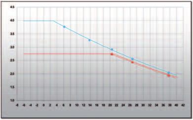
Case Study: Installazione EEV per TELECOM Italia

La soluzione EEV (Electronic Expansion Valve) integrata ai controllori della serie pCO fornita da CAREL           La soluzione
è stata installata ed analizzata presso un impianto TELECOM ITALIA di Mestre (Venezia), su di un chiller
ad acqua della capacità di 110kW per ciascuno dei due circuiti ad R22, con valvola termostatica mecca-
nica (TEV), due compressori a doppio stadio e regolazione della condensazione a gradini.

Il retrofit ha previsto la realizzazione, su uno dei due circuiti, di due linee di espansione in parallelo, una
con TEV e l’altra con EEV, attivate alternativamente da valvole solenoide; in questo modo siamo stati in
grado di condurre una prova comparativa tra i due sistemi alle stesse condizioni ambientali e di carico.

Un driver CAREL serie EVD misura, tramite due sonde, il surriscaldamento e posiziona la valvola con
logica PID in modo da garantire la massima efficienza dell’evaporatore, secondo lo schema qui di
seguito.

                                             EVD

                 EEV
dal
condensatore

                                        evaporatore
                                                                                                   al
                                                                                                   compressore

Driver e valvola elettronica sono integrati ad un controllore CAREL serie pCO che regola la pressione di
condensazione del circuito in maniera continua, comunicando con un modulo a taglio di fase, e che
misura il consumo di energia elettrica e la resa frigorifera lato acqua. Il controllore pCO si occupa anche
di gestire il cambio alternato delle due tecnologie di regolazione.

Entrambi i controllori sono gestibili in supervisione grazie al PlantVisor che permette di monitorare e
impostare i parametri macchina da remoto.

La macchina analizzata è integrata in un sistema costituito da 6 chiller di caratteristiche simili che com-
plessivamente forniscono alla centrale una resa frigorifera massima di circa 900kW

Grazie alla regolazione PID del surriscaldamento effettuata dall’EVD, l’evaporatore viene sfruttato al            Perché si risparmia
meglio in ogni condizione (surriscaldamento medio più basso), aumentando la resa della macchina                   utilizzando le valvole
rispetto alla valvola meccanica.
Grazie, inoltre, all’elevata capacità di modulazione ed adattamento delle EEV è possibile spingere l’unità        elettroniche?
chiller alla massima efficienza, diminuendo la pressione di condensazione fino a 10bar e quindi ridu-
cendo i consumi elettrici quando la temperatura ambiente esterna lo consente (notte, mesi autunnali
ed invernali).

La valvola meccanica limita invece la macchina a funzionare sempre a pressioni di condensazione
superiori ai 15bar. Nelle giornate calde, quindi, il vantaggio delle EEV si esplicita in un 4-5% relativo al
miglior utilizzo dell’evaporatore. In quelle fredde, a questo vantaggio si unisce la minore pressione di
lavoro della macchine e quindi la riduzione dei consumi e l’aumento della resa.

+402200120 rel. 1.0 - 01.03.2006                                                                                                           3
                                                                                                                       italiano
Case Study: Installazione EEV per TELECOM Italia
Svolgimento della Lo scopo è stato misurare le prestazioni del chiller (COP) ed il conseguente consumo di energia elet-
prova trica nel funzionamento con EEV e con TEV a parità di condizioni di funzionamento, alternando le due
tecnologie per intervalli di tempo adeguati.
Le misurazioni sono state eseguite impostando le esatte pressioni alle quali il chiller lavora nei diversi
periodi dell’anno, in modo da generare un profilo di efficienza delle due tecnologie in funzione della
temperatura ambiente esterna
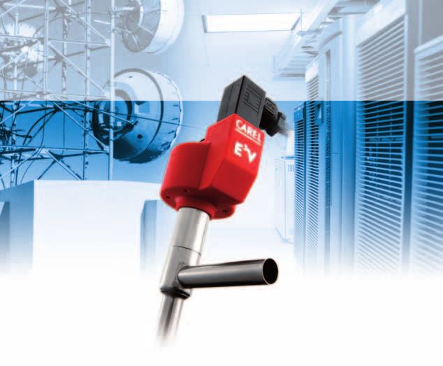
Il grafico seguente mostra la differenza dei rendimenti (COP) della macchina nelle due tecnologie.
Elettronica (EEV)
Meccanica (TEV)
Efficienza (COP)
Temperatura ambiente °C
Risultati Dai dati ottenuti si estrapola, noto il consumo mensile in kWh di tutta la centrale di condizionamento
ed il profilo delle temperature ambiente medie di Mestre, il consumo totale in TEV ed EEV per l’intero
impianto nell’arco dell’anno.
È implicito che ciò è stato ottenuto considerando analogo il rendimento degli altri chiller nelle due
tecnologie rispetto al chiller in prova.
I risultati sono visibili dai diagrammi a seguire, in cui si evidenzia il miglior rendimento ottenuto dal
funzionamento in valvola elettronica.
Risparmio
Costo EEV
Mese dell’anno
Costo TEV
Mese dell’anno
4 +402200120 rel. 1.0 - 01.03.2006Case Study: Installazione EEV per TELECOM Italia
Il diagramma in Fig. 2 mostra l’andamento dei consumi della centrale, tradotto in Euro, nell’arco del-
l’anno, considerando un costo di 0.09€/kWh: si ricava un consumo totale di 141.000 € in funzio-
namento con TEV e di 121.000 € con sistema EEV CAREL (il risparmio distribuito nell’anno solare si
deduce dal diagramma piccolo in riquadro di Fig. 2).
Il risparmio in un anno è quindi di 20.000 € per l’installazione in oggetto, pari al 14,2 %.
Considerando, inoltre, che per ogni kWh consumato dalla rete elettrica nazionale vengono introdotte
in atmosfera 0,58 kg di CO2 (dati ENEL del 1999), il risparmio energetico misurato comporta una
riduzione delle emissioni di anidride carbonica pari a 130.000 kg/anno per l’impianto in oggetto.
L’esperienza ha mostrato un sensibile margine di miglioramento per il risparmio energetico nel condi- Conclusione
zionamento per applicazioni TELECOM.
Per un impianto con capacità nominale di 900 kW abbiamo misurato un risparmio energetico
del 14,2%, che per l’impianto in oggetto si traduce in 20.000 €/anno.
Parallelamente si migliora l’impatto ambientale che la produzione di energia elettrica comporta in
termini di emissione di CO2.
+402200120 rel. 1.0 - 01.03.2006 5
italianoNote:
Case Study: EEV installation for TELECOM Italia

The EEV solution (Electronic Expansion Valve) integrated into the pCO series controllers supplied by         The solution
Carel was installed and analysed at a TELECOM ITALIA installation in Mestre (Venice), on a 110 kW
water chiller in each of the two circuits operating on R22, with a mechanical thermostatic valve (TEV),
two dual-stage compressors and stepped condenser control.

This retrofit solution involved the creation, in one of the two circuits, of two parallel expansion lines,
one with a TEV and the other with an EEV, activated alternately by solenoid valves; this allowed compa-
rative tests to be conducted between the two systems in the same environmental and load conditions.

A CAREL EVD series driver was used to control, based on the readings from two probes, the superheat
and valve positions with PID logic, so as to guarantee the maximum efficiency of the evaporator, accor-
ding to the diagram below.

                                           EVD

                EEV
from
condenser

                                       evaporator
                                                                                              to
                                                                                              compressor

The driver and electronic valve were integrated into a CAREL pCO series controller that continuously
monitors the condensing pressure in the circuit, communicating with a phase control module, and
measuring the electricity consumption and water-side cooling capacity. The pCO controller also mana-
ges the changeover between the two control technologies.

The controllers can be connected to the PlantVisor supervisor for monitoring and setting the unit para-
meters from a remote position.

The unit analysed is part of a system made up of 6 chillers with similar characteristics, and which
together provide the installation a maximum cooling capacity of around 900 kW.

With the PID superheat control performed by the EVD driver, the evaporator is exploited to the best in       Why is energy saved by
all conditions (lower average superheat), increasing the efficiency of the unit compared to operation        using electronic valves?
with the mechanical valve.
In addition, the high modulation and adaptation capacity of the electronic expansion valve (EEV)
means that the chiller can be operated at maximum efficiency, decreasing the condensing pressure to
10 bar and as a consequence reducing power consumption when the outside temperature is suitable
(at night or during the autumn and winter months)

The mechanical valve, on the other hand, forces the unit to always operate at condensing pressures
in excess of 15 bar. On hotter days, then, the advantage of the EEV means a 4-5% better use of the
evaporator. On colder days, this advantage combines the lower operating pressure of the units with a
reduction in power consumption and an increase in efficiency.

+402200120 rel. 1.0 - 01.03.2006                                                                                  english           3
Case Study: EEV installation for TELECOM Italia
Implementation of the The purpose of the trial was to measure the performance of the chiller (COP) and the consequent
trial electricity consumption in operation with the EEV and with the TEV in the same operating conditions,
alternating the two technologies for suitable intervals of time.
The measurements were made by setting the exact operating pressure of the chiller for the different
periods of the year, so as to generate an efficiency profile of the two technologies according to the
outside temperature.
The following graph shows the difference in efficiency (COP) of the unit using the two technologies.
Electronic (EEV)
Mechanical (TEV)
efficiency (COP)
Ambient temperature °C
Results Based on the known monthly consumption in kWh of the entire air-conditioning system and the profile
of the average temperature in Mestre, the data resulting from the tests, when extrapolated, gives the
total consumption in TEV and EEV operating modes for the entire installation over the year.
It is implicit that the efficiency of the other chillers is considered to be similar to the chiller used in the
tests when implementing the two technologies.
The results can be seen in the following diagrams, which highlight the better efficiency achieved during
operation with the electronic valve.
saving
Cost with EEV
Month
Cost with TEV
Month
4 +402200120 rel. 1.0 - 01.03.2006Case Study: EEV installation for TELECOM Italia The diagram in Fig. 2 shows the trend in the power consumption of the installation over the year, in euro, considering an electricity cost of 0.09 €/kWh: the total consumption is € 141,000 in TEV opera- tion and € 121,000 with the CAREL EEV system (the savings distributed over the calendar year can be seen in the small chart at the top of the graph). The savings over one year are consequently € 20,000 for the installation in question, equal to14.2 %. Considering, furthermore, that for each kWh consumed by the national grid, 0.58 kg of CO2 is introdu- ced into the atmosphere (source: ENEL, 1999), the energy savings achieved also involve a reduction in carbon dioxide emissions of 130,000 kg/year for the installation in question. The experience has shown considerable margins of improvement in terms of energy savings in air-con- Conclusions ditioning systems for TELECOM applications. For an installation with a rated capacity of 900 kW the energy savings achieved were 14.2%, which for the installation in question means € 20,000 per year. At the same time, there is a reduction in the environmental impact in terms of CO2 emissions from the generation of electricity. +402200120 rel. 1.0 - 01.03.2006 english 5
Note:
+402200120 - 1.0 - 01.03.06
Headquarters

CAREL S.p.A.
Via dell’Industria, 11 - 35020 Brugine - Padova (Italy)
Tel. (+39) 0499 716611 - Fax (+39) 0499 716600
carel@carel.com - www.carel.com

Subsidiaries                                              Affiliated Companies:

CAREL Australia Pty Ltd                                   CAREL Korea Co. Ltd.
www.carel.com.au                                          www.carel.co.kr
sales@carel.com.au                                        info@carel.co.kr

CAREL China Ltd.                                          CAREL (Thailand) Co. Ltd.
www.carelhk.com                                           www.carel.co.th
sales@carelhk.com                                         info@carel.co.th

CAREL Deutschland GmbH
www.carel.de
info@carel.de

CAREL Export
www.carel.com
carelexport@carel.com

CAREL France Sas
www.carelfrance.fr
carelfrance@carelfrance.fr

CAREL Italia
www.carel.it
carelitalia@carel.com

CAREL Sud America Ltda.
www.carel.com.br
carelsudamerica@carel.com.br

CAREL U.K. Ltd.
www.careluk.co.uk
careluk@careluk.co.uk

CAREL USA L.L.C.
www.carelusa.com
sales@carelusa.com

                                                                                      © CAREL S.p.A. 2006 all rights reserved

                                                                                      CAREL reserves the right to modify the features of
                                                                                      its products without prior notice.
www.carel.com
Puoi anche leggere