SLT972 - SLT974 - SLT979 - ISTRUZIONI PER INSTALLAZIONE USO E MANUTENZIONE INSTALLATION, USE AND MAINTENANCE INSTRUCTION - DAKE
←
→
Trascrizione del contenuto della pagina
Se il tuo browser non visualizza correttamente la pagina, ti preghiamo di leggere il contenuto della pagina quaggiù
INFORMAZIONI COMMERCIALI PER I CONSUMATORI
COMMERCIAL INFORMATION FOR THE CONSUMER

IT   ISTRUZIONI PER INSTALLAZIONE USO E MANUTENZIONE
GB   INSTALLATION, USE AND MAINTENANCE INSTRUCTION

SLT972 - SLT974 - SLT979

INFORMAZIONI TECNICHE
TECHNICAL INFORMATION
2
1

2

3
    3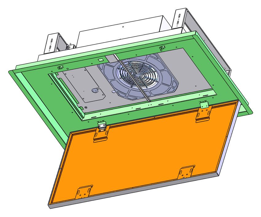
4       5

6       7

8       9
    4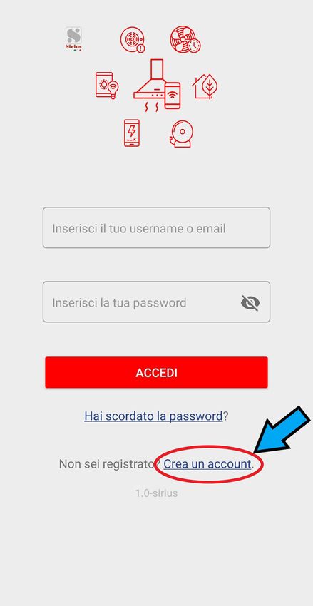
10

11

12
     5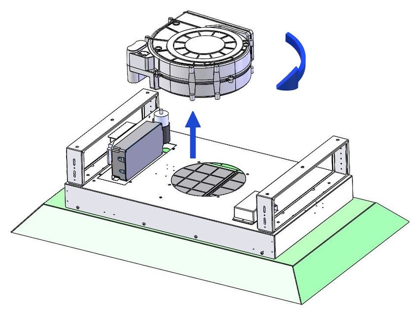
13

14

     6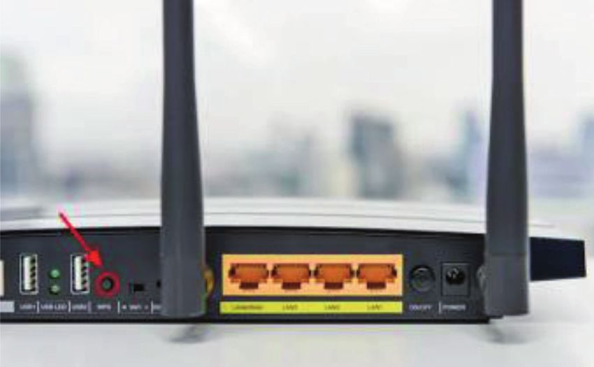
INDICE       IT

Avvertenze

Sistema d’uso

Installazione

Funzionamento

Manutenzione

                         7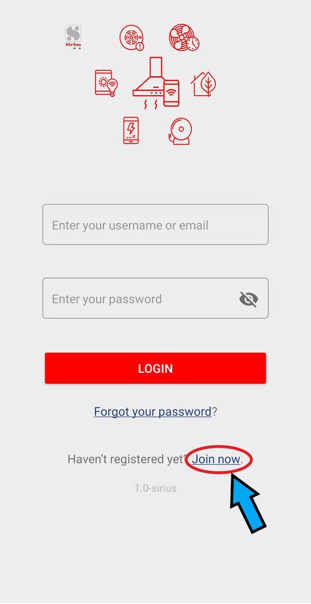
- I bambini non devono giocare
        AVVERTENZE                          con l’apparecchio.

                                            - la pulizia e la manutenzione
L’uscita aria dell’apparecchio, non         non devono essere eseguite da
deve essere collegata ad un con-            bambi ni senza supervisione.
dotto usato per lo scarico di altri
fumi quali impianti di riscaldamen-         - Se il cavo di alimentazione è
to, scaldabagni, ecc..                      danneggiato, esso deve essere
Per l’emissione all’esterno dell’aria       sosti tuito da un cavo o da un as-
rispettare le norme vigenti.                semblaggio speciale, disponibili
                                            presso il costruttore o il suo ser-
L’alimentazione per il motore della         vizio assistenza tecnica.
centralina avviene tramite la cap-
pa posta in cucina.                         - Il locale deve disporre di ade-
Prima del collegamento elettrico            guata ventilazione quando si
assicurarsi che i valori di tensione        utilizza la cappa da cucina con-
dell’abitazione corrispondano con           temporaneamente con altri ap-
quelli delle traghette dati elettrici       parecchi che impiegano gas o
dell’apparecchio.                           altri combustibili (non si applica
                                            agli apparecchi che si limitano a
Prima di procedere a qualsiasi              scaricare nuovamente l’aria nel
tipo di operazione di pulizia o ma-         locale);
nutenzione assicurarsi che l’appa-
recchio sia scollegato dalla rete           - Esiste la possibilità di incendio
elettrica.                                  qualora le operazioni di pulizia
                                            non vengano effettuate secondo
Una buona manutenzione garanti-             quanto indicato nelle istruzioni;
sce un buon funzionamento ed un
buon rendimento nel tempo.                  - Non preparare alimenti flambé
                                            sotto la cappa da cucina.
Tutti i modelli sono in classe I per-
tanto necessitano di collegamento           ATTENZIONE: Le parti accessi-
a terra.                                    bili possono scottare se utilizzate
                                            in concomitanza con gli apparec-
- Questo apparecchio può essere             chi di cottura.
utilizzato da bambini di età pari o
superiore a 8 anni e da persone
con ridotte capacità fisiche, sen-
soriali o mentali o mancanza di
esperienza e conoscenza se sono
stati sottoposti a supervisione o
istruzione sull’uso dell’apparec-
chio in modo sicuro e comprendo-
no pericoli coinvolti.
                                        8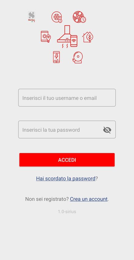
INSTALLAZIONE
         VERSIONI D’USO
                                                               SLT972_4V - SLT974_4V
                                                                    SLT979_4V
APERTURA PANNELLI
E’ possibile aprire i pannelli di copertura dei filtri
antigrasso tirandoli delicatamente come indicato             Estrarre il prodotto dalla confezione e collocarlo
in fig. 1.                                                   su una superficie adatta: suggeriamo di usare un
                                                             morbido materiale, come una spugna o un panno.
Per un adeguato funzionamento si consiglia di in-            Aprire il pannello ruotandolo come mostrato in
stallare il prodotto ad una distanza massima, dal            Fig.1 e rimuovere i filtri antigrasso.
livello del pavimento, di 2000 - 2100 mm.
                                                             L’ apertura che ospiterà la cappa dovrà essere:
Prima di procedere nell’installazione dell’appa-             SLT972 750x410mm
recchio verificare che tutti i componenti non siano          SLT974 815x465mm
danneggiati, in caso contrario contattare il riven-          SLT979 1050x645mm
ditore e non proseguire con l’installazione.
Utilizzare un tubo di evacuazione aria che abbia             La distanza tra il cartongesso e il soffitto solido do-
la lunghezza massima non superiore a 5 metri.                vrà essere compreso tra le seguenti dimensioni:
- Limitare il numero di curve nella canalizzazio-            SLT972 : da 160 a 230mm
ne poiché ogni curva riduce l’efficienza di aspi-            SLT974 : da 200 a 270mm
razione equiparata a 1 metro lineare. (Es: se si             SLT979 : da 210 a 280mm
utilizzano n°2 curve a 90°, la lunghezza della ca-           Per distanze superiori è opportuno realizzare
nalizzazione non dovrebbe superare i 3 metri di              delle adeguate staffe robuste che colleghino la
lunghezza).                                                  cappa al soffitto solido.
- Evitare cambiamenti drastici di direzione.
- Utilizzare un condotto con diametro da                     Occorre predisporre una adeguata canalizzazio-
150mm/200mm costante per tutta la lunghezza.                 ne dell’aria all’interno della nicchia in cartonges-
- Utilizzare un condotto di materiale approvato              so ed il collegamente alla rete elettrica, necessa-
normativamente.                                              ria ad alimentare la cappa.
                                                             Suggeriamo di completare la nicchia in carton-
                                                             gesso solo dopo aver installato completamente
                                                             il prodotto, questo al fine di poter effettuare tutti i
                                                             collegamenti (elettrici e alla tubatura uscita aria)
                                                             in maniera agevole.

                                                             Praticare i fori nel soffitto solido , come mostra-
                                                             to in fig. 2 - 3 - 13, inserire i tasselli di plastica
                                                             nei fori praticati e fissare le staffe al soffitto come
                                                             mostrato in 4. Le staffe sono telescopiche, que-
                                                             sto per permettere l’escursione indicata al punto
                                                             precedente.

                                                             Nel caso si intenda orientare l’uscita aria del pro-
                                                             dotto, in una direzione diversa da quella prestabilita
                                                             in fabbrica, è possibile smontare il box ventilatore
                                                             (vedi fig.5), agendo sulle otto viti di fissaggio, quindi
                                                             ruotarlo e posizionarlo come si desidera, ripristinare
                                                             le otto viti di fissaggio rimosse in precedenza.

                                                             Portare la cappa vicino alle staffe precedente fis-
                                                             sate al soffitto solido, collegare l’apparecchio alla
                                                             rete elettrica, collegare la canalizzazione uscita aria
                                                             quindi fissare il prodotto al soffitto, usando le viti for-
                                                             nite in dotazione, come mostrato in Fig. 6.
                                                             Ripristinare il filtro antigrasso e chiudere il pannello.
                                                         9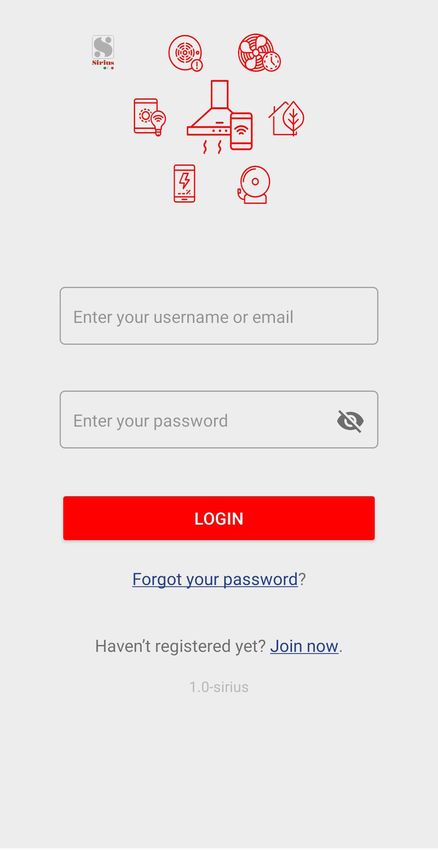
INSTALLAZIONE
MOTORE ESTERNO
SLT972_BRHM-SLT974_BRHM
SLT979_BRHM
I prodotti con motore esterno possono essere in-
stallati seguendo le stesse istruzioni degli stessi
Estrarre il prodotto dalla confezione e collocarlo con motore a bordo come descritto nelle pagine
su una superficie adatta: suggeriamo di usare un precedenti.
morbido materiale, come una spugna o un panno. Dopo l’installazione della cappa, seguire le istru-
Aprire il pannello ruotandolo come mostrato in zioni descritta nel motore remoto per completare
Fig. 1 e rimuovere i filtri antigrasso. l’installazione.
Il cavo del motore remoto deve essere collegato
L’ apertura che ospiterà la cappa dovrà essere: alla morsettiera specifica posizionata all’interno
SLT972 750x410mm della scatola in plastica di colore nero, presente
SLT974 815x465mm nella cappa.
SLT979 1050x645mm
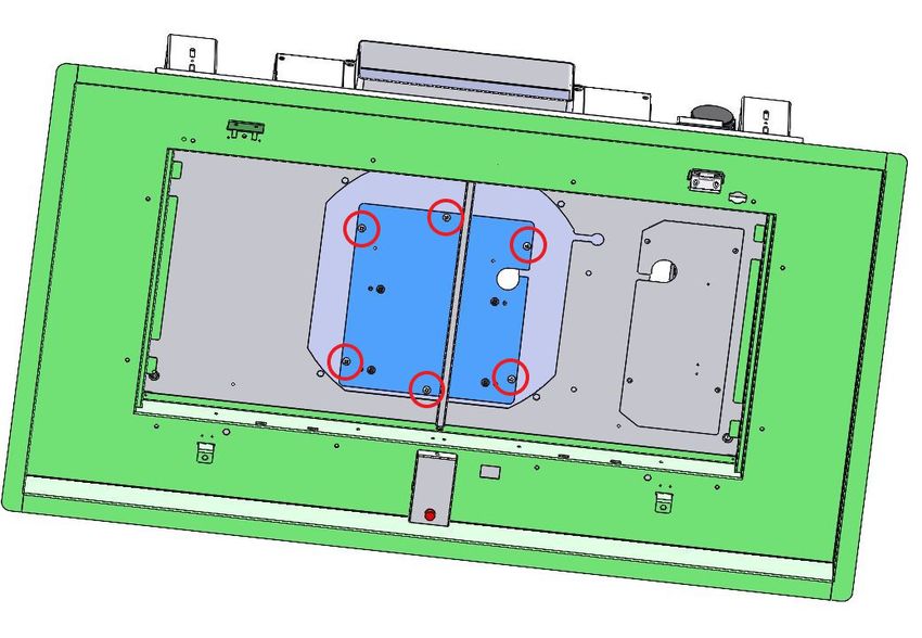
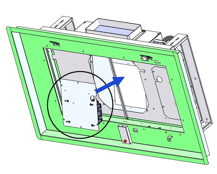
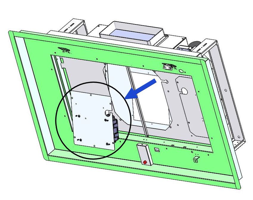
La distanza tra il cartongesso e il soffitto solido Per collegare il motore remoto alla morsettiera,
dovrà essere compreso tra le seguenti dimensio- svitare le 6 viti presenti all’interno della cappa
ni: (fig. 7) ed abbassare la staffa sostegno mor-
SLT972 : da 160 a 230mm settiera (fig. 8). Collegare il motore remoto alla
SLT974 : da 200 a 270mm morsettiera presente nella scatola in plastica di
SLT979 : da 210 a 280mm colore nero (fig. 9) e riposizionare la staffa nella
Per distanze superiori è opportuno realizzare condizione iniziale (fig. 10).
delle adeguate staffe robuste che colleghino la
cappa al soffitto solido.
Occorre predisporre una adeguata canalizzazio
ne dell’aria all’interno della nicchia in cartonges
so ed il collegamente alla rete elettrica, necessa
ria ad alimentare la cappa.
Suggeriamo di completare la nicchia in carton
gesso solo dopo aver installato completamente
il prodotto , questo al fine di poter effettuare tutti i
collegamenti (elettrici e alla tubatura uscita aria)
in maniera agevole.
Praticare i fori nel soffitto solido , come mostrato
in fig. 11 - 14, inserire i tasselli di plastica nei fori
praticati e fissare le staffe al soffitto come mostrato
in 4. Le staffe sono telescopiche, que sto per per-
mettere l’escursione indicata al punto precedente.
Nel caso si intenda orientare l’uscita aria del
prodotto, in una direzione diversa da quella pre
stabilita in fabbrica, è possibile smontare il ven-
tilatore (vedi fig.12), agendo sulle quattro viti di
fissaggio, quindi ruotarlo e posizionarlo come si
desidera, ripristinare le quattro viti di fissaggio ri-
mos se in precedenza.
Portare la cappa vicino alle staffe precedente fis-
sate al soffitto solido, collegare l’apparecchio alla
rete elettrica, collegare la canalizzazione uscita aria
quindi fissare il prodotto al soffitto, usando le viti for-
nite in dotazione, come mostrato in Fig. 6.
Ripristinare il filtro antigrasso e chiudere il pannello.
10FUNZIONE LUCI DIMMERABILE
FUNZIONAMENTO TALE FUNZIONE PREVEDE LA DIMMERA-
BILITA’ DELLE LUCI DAL 20% FINO AL 100%
TRAMITE LA PRESSIONE CONTINUATA DEL
RADIOCOMANDO SERIE TASTO LUCE DEL TELECOMANDO.
RC001
LE FUNZIONI SONO LE SEGUENTI:
Radiocomando per il comando a distanza di cap-
pe aspiranti.
- LUCE CAPPA SPENTA - PRESSIONE BREVE
DEL TASTO - ACCENZIONE LUCE AL 100%.
CARATTERISTICHE TECNICHE
- Alimentazione pila alkalina: 12V mod. 27A
- LUCE ACCESA AL 100% - PRESSIONE BRE-
- Frequenza di lavoro: 433,92 Mhz
VE DEL TASTO - SPEGNIMENTO LUCE.
- Combinazioni: 32.768
- Consumo max.: 25 mA
- LUCE ACCESA AL 100% - PRESSIONE CON-
- Temperatura d’esercizio: -20 ÷ + 55 °C
TINUATA DEL TASTO - DIMINUZIONE DELLA
- Dimensioni: 130x45x15mm.
LUMINOSITÀ.
DESCRIZIONE DI FUNZIONAMENTO
- RILASCIO DEL TASTO DURANTE LA DIMINU-
Il trasmettitore è dotato di 5 tasti per la gestione
ZIONE O INCREMENTO - LA LUCE RIMANE
del funzionamento della cappa, come di seguito
NELL’INTENSITÀ OTTENUTA.
specificato:
- LUCE ACCESA DIMMERATA - NUOVA PRES-
: interruttore ON/OFF luce. SIONE CONTINUATA DEL TASTO - INVERSIONE
: interruttore ON (1° velocità) OFF motore. LUMINOSITA’ RISPETTO ALLA PRECEDENTE.
: diminuire velocità.
SETTAGGIO TEMPERATURA COLORE
: aumentare velocità.
: temporizzatore 10 minuti. Assicurarsi che le luci ed il ventilatore siano
spenti.
La velocità di aspirazione impostata viene indica- Tenendo premuto il tasto TIMER , viene accesa
ta mediante il led presente nel canale perimetrale la luce nella temperatura colore impostata in pre-
di aspirazione. cedenza.
Ad ogni colore generato dal led, corrisponde una Premere e mantenere premuto il tasto Luce per
determinata velocità come indicato sotto: variare la temperatura colore.
Prima velocità colore BIANCO Fintanto che il tasto viene mantenuto premuto,
Seconda velocità colore AZZURRO viene variata la temperatura colore da calda a
Terza velocità colore BLU fredda, basta lasciare il tasto Luce per seleziona-
Quarta velocità colore ROSSO re il colore desiderato.
Uscire dalla funzione di selezione della tempera-
tura colore premendo il tasto ON/OFF.
11CONDIZIONE INIZIALE DI FUNZIONAMENTO Ripristino della configurazione di Fabbrica:
Il radiocomando viene fornito dal costruttore Se si desidera ripristinare la configurazione di
pronto per l’uso, contenente già dei codici prede- Fabbrica, occorre eseguire la procedura nel se-
finiti di Fabbrica. guente modo: premere contemporaneamente i
tasti:
in modo continuo per 2 secondi, nello stesso
istante si avrà l’accensione dei Led, successiva-
mente premere i tasti:
MODALITÀ DI FUNZIONAMENTO
Configurazione standard:
La configurazione di fabbrica prevede che tut-
ti i sistemi “ cappa - radiocomando “ abbiano lo (entro 5 secondi), 6 lampeggi dei Led indicheran-
stesso codice di trasmissione. Nel caso siano no che l’operazione è stata completata.
installati due sistemi “ cappa - radiocomando “ ATTENZIONE! Questa operazione cancella in
nello stesso locale o nelle immediate vicinanze maniera definitiva i codici preesistenti.
i sistemi avendo lo stesso codice di trasmissione
potrebbero essere influenzati quindi è necessario Tasto d’emergenza:
cambiare il codice di un solo radiocomando. In caso di non funzionamento del radiocomando,
per lo spegnimento dell’apparecchiatura, interve-
Generazione di un nuovo codice trasmissio- nire sul tasto d’emergenza. Dopo eventuali ripa-
ne: razioni, ripristinare il tasto d’emergenza.
Il radiocomando viene fornito dalla fabbrica con
dei codici predefiniti. Se si desidera una nuova ATTENZIONE
generazione di codici, occorre eseguire la proce- La batteria deve essere sostituita ogni anno
dura nel seguente modo: premere contempora- per garantire la portata ottimale del trasmet-
neamente i tasti: titore.
Per sostituire la batteria scarica rimuovere il
coperchio di plastica, togliere la batteria in uso
e inserirne una nuova rispettando la polarità
in modo continuo per 2 secondi, nello stesso indicata nel contenitore.
istante si avrà l’accensione dei Led, successiva- La batteria usata deve essere smaltita negli
mente premere i tasti: appositi raccoglitori.
Il prodotto
(entro 5 secondi), 3 lampeggi dei Led indicheran- Radiocomando RC001
no che l’operazione è stata completata. è conforme alle specifiche della Direttiva
RED 2014/53/EU.
ATTENZIONE! Questa operazione cancella in
maniera definitiva i codici preesistenti.
AVVERTENZE
Apprendimento del nuovo codice di trasmis- Cambiamenti o modifiche non espressamente
sione: approvate dal detentore del certificato di com-
Dopo aver cambiato il codice di trasmissione nel patibilità alle norme possono invalidare il di-
radiocomando, occorre far apprendere alla cen- ritto dell’utente all’utilizzo dell’apparecchiatura
trale elettronica della cappa aspirante il nuovo
codice nel seguente modo: Rev. 0 26/08/14
Premere il pulsante di spegnimento generale
della cappa (Fig. 15), ripristinare l’alimentazione Il prodotto è dotato di un dispositivo elettronico
alla centrale elettronica, da questo momento ci che permette lo spegnimento automatico dopo
sono 15 secondi di tempo per premere il tasto quattro ore di funzionamento dall’ultima opera-
Luce: per far sì che la centrale si sincronizzi zione eseguita.
con il nuovo codice.
12TEMPORIZZAZIONI
Con l’entrata in vigore dal 1° Gennaio 2015 dei
nuovi regolamenti della Commissione Europea
EU65 “Energy label” e EU66 “ Ecodesign”, ab-
biamo reso conforme i prodotti in base ai requisiti
richiesti.
Tutti i modelli nelle versioni energy label dispon-
gono di una elettronica, con funzioni di temporiz-
zazione delle velocità di aspirazione, superiore a
650m³/h.
In effetti i modelli con motore a bordo, con porta-
ta massima superiore a 650m³/h, prevedono la
IVa velocità temporizzata dopo 5 minuti di funzio-
namento, Trascorsi i tempi di cui sopra il motore
di aspirazione passa alla IIIa velocità in maniera
automatica.
I prodotti in versione external motor, vengono
abbinati soltanto con motori remoti dove, come
per la versione con motore a bordo, vengono
temporizzate le velocità con portate superiori a
650m³/h. (Vedi istruzioni riportate nei motori re-
moti).
I motori remoti, che hanno una portata superio-
re a 650m³/h sia alla IVa che alla IIIa velocità,
vengono automaticamente temporizzate come
segue: dalla IVa velocità, dopo 6 minuti di funzio-
namento passa automaticamente alla II velocità.
Se il prodotto viene impostato alla IIIa velocità,
passa automaticamente alla II velocità dopo 7
minuti. Resta comunque possibile modificare le
velocità in uso.
Il prodotto in modalità stand-by ha un consumo
inferiore a 0.5W.
13SCARICARE L’APP CREA IL TUO ACCOUNT
SIRIUS PER ANDROID SULLA APP SIRIUS
(è necessaria la versione 5 o superiore). 1. Nella Home page della App, cliccare su Crea
un account.
1. Accedere all’App Google Play Store .
2. Cercare l’App SIRIUS CAPPE DA CUCINA.
3. Selezionarla.
4. Cliccare per installare.
5. Seguire le istruzioni sullo schermo per completa-
re l’operazione e scaricare il contenuto.
E’ possibile variare la lingua accedendo a Google
Play dal proprio computer e variando le impostazio-
ni dei propri Account Google.
Note: le App sono progettate per essere utilizzate
da dispositivi che supportano il Sistema Android e
Chromebook e non possono essere utilizzate su
computer con sistemi informativi Windows o Mac.
SCARICARE L’APP
SIRIUS PER IOS
(è necessaria la versione 10).
Note:
• Dopo aver effettuato la richiesta App, è possibi-
le che ti venga richiesto di verificare la tua identità
inserendo la password o utilizzando il Touch ID o
Face ID.
• Le istruzioni di seguito non si applicano all’iPhone
5c, iPhone 5, iPhone 4s o all’iPhone 4.
1. Accede all’App Store .
►Per installare le App, è necessario iscriversi
con un Apple ID o crearne uno.
2. Per cercare l’App Store, cliccare Apps (in basso).
3. Selezionare Ricerca (in basso), quindi
accedere alla App SIRIUS CAPPE DA CUCINA.
4. Selezionare l’App.
5. Selezionare OTTIENI quindi cliccare su IN
STALLAZIONE.
► Se hai un iPhone compatibile con Face ID
attivato, selezionare due volte il tasto Lato quin
di guardare verso lo schermo per effettuare l’au
tenticazione.
6. Se richiesto, iscriversi allo Store iTunes per
completare l’installazione. 142. Inserisci i dati del tuo Account. Nota: Le invieremo una mail dall’indirizzo
no_reply@siriuscappe.com, affinché possa ve-
Nota: utilizza il tuo indirizzo mail o il tuo cellulare. locemente trovarla. Qualora non fosse presente
nella posta in arrivo, le consigliamo di cercare
all’interno delle cartelle. Se dovessero essere
state impostati un filtro spam o una regola, la
mail di riferimento potrebbe trovarsi nella car-
tella Spam, Junk, Trash, Posta eliminata o nella
cartella Archivio. Qualora non fosse presente, la
invitiamo a creare un nuovo account.
5. Nella pagina Login, inserire la propria e mail
e password di accesso all’account e cliccare
LOGIN.
Esprimi il tuo consenso relativamente alle con-
dizioni generali relative alla privacy, quindi clicca
Accedi.
3. se tutte le istruzioni sono state eseguite cor-
rettamente, comparirà una finestra Popup con il
seguente messaggio “Registrazione avvenuta
con successo. Controlla la tua mail per il link
di attivazione”.
4. Accedi alla tua casella di posta elettronica e
conferma il tuo account.
Nota: Se hai dimenticato la password, clicca su
Hai dimenticato la password? Inserisci il tuo
indirizzo e-mail e clicca su Inviami un link.
Cliccare qui.
152. Selezionare AGGIUNGI NUOVO DISPOSITI-
ABBINARE IL TUO VO.
PRODOTTO
Un modo veloce è utilizzare la procedura WPS;
qualora il router non sia dotato del tasto WPS,
seguire le istruzioni a pag. 18.
ABBINARE LA MODALITA’ WPS
1. Dopo aver effettuato l’accesso, seleziona il
Menù della App (in alto a sinistra), quindi
DISPOSITIVI.
163. Selezionare UTILIZZA LA MODALITA’ WPS 4. Sulla tua cappa a soffitto:
• prendere il telecomando;
• spegnere completamente la cappa (luce e
motore);
• tenere premuto il tasto ON /OFF per accede-
re al menu di configurazione WI-FI, finché il LED
giallo dell’indicatore di velocità non inizierà a lam-
peggiare;
• premere brevemente il tasto ON/OFF per
scorrere all’interno delle funzioni del menu; ogni
colore identifica una differente funzione:
- GIALLO = WI-FI ACCESO;
- BIANCO = ABBINAMENTO MODALITA’
WPS;
- AZZURRO = ABBINAMENTO CONNESSIONE
IN MODALITA’ MANUALE;
- BLU = WI-FI SPENTO;
- ROSSO = RESET DI FABBRICA.
• In caso di opzione ABBINAMENTO MODALITA’
WPS, selezionare il colore BIANCO e tenere pre-
muto il tasto ON / OFF per impostarlo (alla con-
ferma finale, il LED passerà dal lampeggio allo
spegnimento).
5. Premere FATTO sulla descrizione WPS.
6. Premere FATTO sulla descrizione WPS.
177. Utilizzare il lettore del codice QR per collega-
re il prodotto alla App, utilizzando l’etichetta sul-
la brochure o utilizzando l’etichetta posizionata
all’interno del prodotto, visibile rimuovendo i filtri
antigrasso.
8. Premere ATTIVARE DISPOSITIVO e riceve-
rai un messaggio pop-up.
9. Selezionare l’icona del dispositivo.
Buon divertimento!
183. Selezionare MODALITA’ DIRETTA DI ISCRI-
ABBINARE LA MODALITA’ ZIONE
MANUALE
1. Dopo aver effettuato l’accesso, selezionare il
Menù della App (in alto a sinistra)
e selezionare DISPOSITIVI.
4. Sulla tua cappa a soffitto:
• Prendere il telecomando;
2. Selezionare AGGIUNGI DISPOSITIVO.
• Spegnere completamente la cappa (luce e
motore);
• Tenere premuto il tasto ON / OFF per accedere
al menù di configurazione WI-FI, finché il LED
giallo non inizierà a lampeggiare;
• premere brevemente il tasto ON / OFF per
scorrere attraverso le funzioni del menù; ogni
colore identifica una differente funzione:
- GIALLO = WI-FI ACCESO;
- BIANCO = ABBINAMENTO MODALITA’
WPS;
- AZZURRO = ABBINAMENTO MODALITA’
MANUALE;
- BLU = WI-FI SPENTO;
- ROSSO = RESET DI FABBRICA.
• In caso di opzione CONNESSIONE IN MODA-
LITA’ MANUALE, selezionare il colore AZZURRO
e tenere premuto il tasto ON / OFF per impostarlo
(alla conferma finale, il LED passerà dal lampeg-
gio allo spegnimento).
195. Selezionare APRI IMPOSTAZIONI. 7. TORNARE INDIETRO.
6. Connettere a “rete della CAPPA”, inserendo
come password il termine “password”.
8. INSERIRE IL NOME E LA PASSWORD WI-FI.
9. Selezionare CONFIGURA.
2010. Nel caso venga evidenziato il seguente mes- SELEZIONARE “Rivendica dispositivo”.
saggio di errore:
Ritornare alla pagina principale.
2111. Utilizzare il lettore del codice QR per collega-
re il prodotto alla App, utilizzando l’etichetta nella
brochure o l’etichetta presente all’interno del pro-
dotto, visibile rimuovendo I filtri antigrasso.
12. Connettere il cellulare alla rete WiFi dome-
stica.
13. Premere ATTIVA DISPOSITIVO e riceverai
un messaggio pop-up.
14. Selezionare l’icona del dispositivo.
Buon divertimento!
222. Su DISPOSITIVI, individua il tuo dispositivo a
RIMUOVERE UN sinistra e selezionare Rimuovi.
DISPOSITIVO DALLA APP.
1. Dopo aver effettuato l’accesso, selezionare il
Menù della App (in alto a sinistra)
e selezionare DISPOSITIVI.
23ILLUMINAZIONE
Selezionare con l’interruttore di riferimento l’ac-
FUNZIONI censione e/o lo spegnimento.
Timer
Selezionare su e impostare i minuti per
lo spegnimento del dispositivo.
Selezionare la barra di scorrimento per impo-
stare la temperatura colore (°K).
Velocità del motore
Digitare la velocità desiderata, “0” per lo spegni-
mento.
Seleziona la barra di scorrimento per la dim-
merabilità delle luci, il cui range varia da 10%
a 100%.
24PULIZIA FILTRI
CONDIVIDERE IL DISPOSITIVO
Selezionare e condividere il dispositivo solo
con un utente già registrato.
RINOMINARE IL DISPOSITIVO
Selezionare e rinominare il dispositivo.
25MANUTENZIONE
Una manutenzione accurata garantisce un buon
funzionamento e prestazioni durature.
Una speciale cura va rivolta al filtro antigrasso:
per accedere al filtro, procedere come descritto
nel Capitolo APERTURA DEL PANNELLO.
Rimuovere il filtro antigrasso, usando l’apposita
maniglia.
Per rimontare il filtro antigrasso dopo la pulizia,
eseguire
la stessa operazione in ordine inverso.
Per rimuovere il filtro al carbone, se installato, se-
guire gli stessi passi come per il filtro antigrasso.
Il filtro a carbone si trova immediatamente sopra
il filtro antigrasso.
L’acqua tiepida e detergenti neutri sono racco-
mandati per pulire l’apparecchio, mentre devono
essere evitati prodotti abrasivi.
Se il cavo di alimentazione è danneggiato, deve
essere sostituito o dal produttore o da un centro
assistenza assistenza o da una persona qualifi-
cata per evitare rischi.
26CONTENTS GB
Warnings
Uses
Installation
Working
Maintenance
27concerning use of the appliance
WARNINGS in a safe way and under stand
the hazards involved.
The air outlet of the appliance - Children shall not play with the
must not be connected to a flue appliance.
which is used for exhausting other
fumes from appliances, such as a - Cleaning and user maintenan-
central heating, boilers etc.. ce shall not be made by children
without supervision.
For the external exhausting of the
fumes, comply with the regula- - If the power cable is damaged,
tions in force. it must be replaced by a cable
or a special assembly, available
The motor of the peripheral from the manufacturer or its ser-
exhausting group is powered by vice de partment technique.
the coo ker-hood placed in the
kitchen. - The room must have adequa-
te ventilation when using the
Before connecting the cooker kitchen hood simultaneously with
hood to the mains supply, make other appliances that use gas or
sure that the voltage indicated in other fuels (not yes applies to
the rating plate corresponds to appliances that simply release
the mains voltage in the home. the air back into the room);
Before carrying out any sort of - There is the possibility of fire if
maintenance or cleaning opera- the cleaning operations are not
tion, make sure that the applian- carried out as indicated in the in-
ce is disconnected from the elec- structions;
trical mains.
- Do not prepare flambéed food
An appropriate maintenance en- under the kitchen hood.
sures a good working and a good
per formance in the long run. ATTENTION: The accessible
parts can burn if used in conjun-
All models are built in class I, the- ction with the cooking applian-
refore they must be earthed. ces.
- This appliance can be used by
children aged from 8 years and
above and persons with reduced
physical, sensory or mental ca-
pabilities or lack of experience
and knowledge if they have been
given supervision or instruction
28INSTALLATION
USES
SLT972_4V - SLT974_4V
SLT979_4V
PANEL OPENING
It is possible to open the panel, which cover the Take the product out of the packaging and place
grease filters, slightly pulling the panel on a side, it on a suitable surface: we Suggest to use a soft
as shown on fig. 1. material, such as a sponge or a cloth.
In order to make the hood working properly, it is Open the glass panel , rotating it as shown in Fig.
recommended to install the appliance at a distan- 1, and remove the grease filters.
ce of 2000 - 2100 mm from the floor.
Where you intend to install the appliance, you
Before starting the appliance installation, please must create a recess which will have a rectangu-
check that all components are not damaged, in lar opening of:
such a case contact your retailer and do not carry SLT972 750x410mm
out installation. SLT974 815x465mm
Furthermore, please read carefully all of the fol- SLT979 1050x645mm
lowing installation instructions.
- Use an exhausting pipe whose maximum length The distance between the plasterboard and the
does not exceed 5 meters. solid ceiling shall be between the following di-
- Limit the no. of elbows in the piping, since each mensions:
elbow reduces the air capacity of 1 linear meter. SLT972 : from 160 to 230mm
(Ex.: if you use no. 2 x 90 ° elbows, the length of SLT974 : from 200 to 270mm
piping must not exceed 3 meters). SLT979 : from 210 to 280mm
- Avoid abrupt direction changes.
- Use a 150 mm constant diameter pipe for the For longer distances it is advisable to make suita-
whole length, or same section. ble sturdy brackets that connect the hood to the
- Use piping approved by standards in force. solid ceiling.
Adequate air ducting must be provided inside the
plasterboard niche and connected to the power
supply, which is necessary to supply the hood.
We suggest to complete the plasterboard niche
only after having completely installed the product,
in order to make all the connections (electrical
and to the air outlet pipe) easily.
Drill the holes in the solid ceiling, as shown in fig.
2 - 3 - 13, insert the plastic plugs into the holes
drilled and secure the brackets to the ceiling as
shown in 4. The brackets are telescopic, to allow
the excursion indicated in the previous point.
If you intend to orient the air outlet of the product,
in a different direction from that established in the
factory, you can dismantle the fan box (see fig.5),
acting on the eight fixing screws, then rotate and
position it as you want, restore the eight fixing
screws removed previously.
29INSTALLATION
EXTERNAL MOTOR
SLT972_BRHM-SLT974_BRHM
SLT979_BRHM
The products functioning with an external motor,
can be installed following the same instructions of
Take the product out of the packaging and place the ones equipped with on - board blowers, which
it on a suitable surface: we Suggest to use a soft are described in the previous sections.
material, such as a sponge or a cloth. After the installation of the hood, follow the in-
Open the glass panel , rotating it as shown in Fig. struction described in the remote motor to com-
1, and remove the grease filters. plete the installation.
The cable of the remote motor must be connec-
Where you intend to install the appliance, you ted to the specific terminal positioned inside the
must create a recess which will have a rectangu black plastic box in the hood.
lar opening of:
SLT972 750x410mm To connect the remote motor to the terminal
SLT974 815x465mm block, unscrew the 6 screws inside the hood (fig.
SLT979 1050x645mm 7) and lower the terminal block support bracket
(fig. 8). Connect the remote motor to the terminal
The distance between the plasterboard and the block in the black plastic box (fig. 9) and reposi-
solid ceiling shall be between the following di tion the bracket in the initial condition (fig. 10).
mensions:
SLT972 : from 160 to 230mm
SLT974 : from 200 to 270mm
SLT979 : from 210 to 280mm
For longer distances it is advisable to make suita
ble sturdy brackets that connect the hood to the
solid ceiling.
Adequate air ducting must be provided inside the
plasterboard niche and connected to the power
supply, which is necessary to supply the hood.
We suggest to complete the plasterboard niche
only after having completely installed the product,
in order to make all the connections (electrical
and to the air outlet pipe) easily.
Drill the holes in the solid ceiling, as shown in
fig. 11 - 14, insert the plastic plugs into the holes
drilled and secure the brackets to the ceiling as
shown in 4. The brackets are telescopic, to allow
the excursion indicated in the previous point.
If you intend to orient the air outlet of the pro-
duct, in a different direction from that established
in the factory, you can dismantle the fan (see fig.
12), acting on the four fixing screws, then rotate
and position it as you want, restore the four fixing
screws removed previously.
30DIMMABLE LIGHTS FUNCTION
WORKING THIS FUNCTION PROVIDES FOR LIGHTS DIM-
MABILITY, RANGING FROM 20% TO 100% , BY
CONTINUOUSLY PRESSING THE LIGHT KEY
RC001 ON THE REMOTE CONTROL.
RADIO CONTROL
FUNCTIONS ARE THE FOLLOWING:
Radio control used for the remote operation of
ducted cooker hoods.
- HOOD LIGHT OFF - SHORTLY PRESS THE
KEY - LIGHT ON AT 100%.
TECHNICAL DATA
- Alkaline battery powered: 12V mod. 27A
- LIGHT ON AT 100% - SHORTLY PRESS THE
- Operating frequency: 433.92 Mhz
KEY - LIGHT OFF.
- Combinations: 32.768
- Max. consumption: 25 mA
- LIGHT ON AT 100% - CONTINOUSLY PRESS
- Operating temperature: -20 ÷ + 55 °C
THE KEY - BRIGHTNESS REDUCTION.
- Dimensions: 130x45x15 mm.
- RELEASING THE KEY DURING REDUCTION
OPERATING DESCRIPTION
OR INCREASE - LIGHT KEEPS THE LUMI-
The transmitter is equipped with 5 buttons for co-
NOUS INTENSITY REACHED.
oker hood management, as specified below:
- LIGHT ON - DIMMED - CONTINOUSLY PRESS
: Light ON/OFF command. THE KEY - BRIGHTNESS IS INVERTED IF
: Motor ON (speed level 1) / OFF command. COMPARED TO THE PREVIOUS FUNCTION.
: Reduce speed.
COLOUR TEMPERATURE SETTING
: Increase speed.
: 10-minute timer. Make sure that the lights and the fan are off.
Holding down the TIMER key will turn on the light
at the previously set colour temperature.
The set suction speed is indicated by the LED in
Press and hold the Light key to change the colour
the suction perimeter channel.
temperature.
To each color generated by the LED, it corre-
As long as the key is kept pressed, the colour
sponds a specific speed, as shown below:
temperature is changed from warm to cold, just
First speed WHITE
leave the Light key to select the desired colour.
Second speed BLUE
Exit the colour temperature selection function by
Third speed DARK BLUE
pressing the ON/OFF key.
Fourth speed RED
31INITIAL OPERATING CONDITION for 2 seconds. When Leds light on, press buttons:
The manufacturer supplies the radio control unit
ready to be used with codes preset in the Factory
(within 5 seconds). Leds flashing 6 times indicate
the procedure is completed.
WARNING! This operation deletes permanen-
tly the preset codes.
Emergency button:
OPERATION MODE In the event that the radio control does not work,
Standard configuration: use the emergency button to switch the appliance
Standard configuration requires all “cooker hoods off. After any necessary repairs have been perfor-
– radio control - system” to be provided with the med, reset the emergency button.
same transmission code. In the event two cooker
hoods – radio control system are installed in the WARNING
same room or nearby, each system may affect The battery should be replaced every year to
the operation of the another. Therefore, the code guarantee the optimal range of the transmitter.
of one radio control system must be changed. To replace the exhausted battery, take the pla-
stic lid off, remove the battery and replace it
Generating a new transmission code: with a new one, observing the correct battery
The radio control system is provided with preset polarities.
codes. Should new codes be required, proceed Used batteries should be discarded in special
as follows: Press simultaneously buttons: collection bins.
The below product:
for two seconds. When Leds light on, press but- RC001 Radio Controll
tons: complies with the specifications set out in the
Directive RED 2014/53/EU.
(within 5 seconds). Leds flashing 3 times indicate WARNING
the procedure is completed. Any adjustments or modifications which have
not been expressly approved by the holder of
WARNING! This operation deletes permanen- the legal conformity certificate may invalidate
tly the preset codes. the user’s rights relating to the operation of
the device.
Learning the new transmission code:
Once the transmission code is changed in the ra- Rev. 0 26/08/14
dio control unit, the electronic central unit of the
cooker hood must be made to set the new code
in the fol- lowing way: The products are endowed with an electronic de-
Press the main power-off button (fig. 15) of the vice which allows the automatic switching off after
hood and then restore power to the electronic 4 hours working from the last operation.
control unit. Within the next 15 seconds, press
the Liight Button to synchronise the central
unit with the code.
Reset of the Factory configuration:
To restore the Factory configuration, follow the
procedure described below: press simultaneou-
sly buttons:
32DOWNLOAD SIRIUS CREATE YOUR ACCOUNT
APP FOR ANDROID ON SIRIUS APP.
(ver. 5 or higher request). 1. From Home App, Tap on Join now.
1. Open the Google Play Store app .
2. Search or browse for SIRIUS RANGE HOODS App.
3. Select it.
4. Tap to Install.
5. Follow the onscreen instructions to complete
the transaction and get the content.
You can change what language is displayed
when you visit Google Play on your computer by
changing your Google Accounts settings.
Note: Apps are designed for use with supported
Android and Chromebook devices and can’t be
used on Windows or Mac computers.
DOWNLOAD THE SIRIUS
APP FOR IOS
(ver.10 request).
Notes:
• After requesting an app, you may be asked to
verify your identity by entering your passcode or
by using Touch ID or Face ID.
• The steps below don’t apply to the iPhone 5c,
iPhone 5, iPhone 4s or the iPhone 4.
1. Open the App Store .
►To install apps, you must sign in with your
Apple ID or create one.
2. To browse the App Store, tap Apps (at the bot
tom).
3. Tap Search (at the bottom) then enter SIRIUS
RANGE HOODS App.
4. Tap the app.
5. Tap GET then tap INSTALL..
► If you have a compatible iPhone with Face
ID enabled, double-tap the Side button then
look at the screen to authenticate.
6. If prompted, sign in to the iTunes Store to
complete the install
332. Insert your Account data. Note: We’ll send the email from
no_reply@siriuscappe.com, so you can quickly
Note: use the email address test or your mobile. search for it. If it isn’t in your inbox, check your
folders. If a spam filter or email rule moved the
email, it might be in the Spam, Junk, Trash, De-
leted Items, or Archive folder. If you didn’t find yet
please create another account.
5. From Login page Insert the e-mail and pas-
sword of your account and tap LOGIN.
Tap Agree with General Privacy and tap on Re-
gister.
3. If all instructions are done correctly a Popup
message “Registration was successful. Check
your email for the activation link” appears.
4. Go to your e-mail address and Confirm your
account.
Note: If you forgot your password, tap on Forgot
your password? insert your e-mail address and
Tap here. tap Send me a Link.
342. Tap ADD NEW DEVICE.
PAIRING YOUR
PRODUCT
Fast way using the WPS procedure, if your rou
ter has not WPS button, please follow the instruc-
tions at pag. 18.
PAIRING WPS MODE
1. After Login Tap the App Menu (top left)
and select DEVICES.
353. Tap USE WPS MODE 4. On your ceiling hood
• Take the remote control
• Turn off the hood completely (light and fan)
• Keep the ON / OFF button pressed to enter the
WI-FI configuration menu, until the yellow LED of
the speed indicator starts to blink
• Briefly press the ON / OFF button to scroll throu-
gh the menu functions, each color identifies a dif-
ferent function:
- YELLOW = WI-FI ON
- WHITE = PAIRING WPS MODE
- LIGHT BLUE = PAIRING MANUAL MODE
CONNECTION
- BLUE = WI-FI OFF
- RED = FACTORY RESET
• In the case of.
PAIRING WPS MODE option,
select the WHITE color and keep the ON /OFF
button pressed to set it (at the final confirmation
the LED will switch from flashing to off).
5. On your Router WI-FI press WPS button
6. Press DONE on WPS description.
367. Use the QR code reader to connect the pro-
duct with the App, using the label on brochure or
using the label located inside the product , visible
by removing the grease filters.
8. Press ACTIVATE DEVICE and you have a
pop-up message.
9. Tap the device icon.
Enjoy with your device.
373. Tap ENROLLMENT_DIRECT_MODE
PAIRING MANUAL
MODE
1. After Login Tap the App Menu (top left)
and select DEVICES
2. Tap ADD NEW DEVICE
4. On your ceiling hood
• Take the remote control
• Turn off the hood completely (light and fan)
• Keep the ON / OFF button pressed to enter the
WI-FI configuration menu, until the yellow LED of
the speed indicator starts to blink.
• Briefly press the ON / OFF button to scroll throu-
gh the menu functions, each color identifies a dif-
ferent function:
- YELLOW = WI-FI ON
- WHITE = PAIRING WPS MODE
- LIGHT BLUE = PAIRING MANUAL MODE
- BLUE = WI-FI OFF
- RED = FACTORY RESET
• In the case of
MANUAL MODE CONNECTION option,
select the LIGHT
BLUE color and keep the ON / OFF button pres-
sed to set it (at the final confirmation the LED will
switch from flashing to off).
385. Tap OPEN SETTINGS. 7. TURN BACK.
6. Connect to “HOOD network” inserting as
password “password”.
8. ENTER WI-FI NAME AND WIFI PASSWORD.
9. TAP CONFIGURE.
3910. In case of following error. TAP “Claim Devices”.
Go back to the home page.
4011. Use the QR code reader to connect the pro-
duct with the App, using the label on brochure or
using the label located inside the product, visible
by removing the grease filters.
12. Connect your mobile to your home WiFi Router
network.
13. Press ACTIVATE DEVICE and you have a
pop-up message.
14. Tap the device icon.
Enjoy with your device.
412. On DEVICES Slide your device on left and tap
REMOVE ONE DEVICE Remove.
FROM APP.
1. After Login Tap the App Menu (top left)
and select DEVICES.
42LIGHT
Slide the toggle switch for switching ON/OFF.
FUNCTIONS
Timer
Tap on and set the minutes for shutting
down the device.
Slide the scrollbar for setting the color tem-
perature (°K).
Fan speed
Tap on the speed you want select, “0” for
switching OFF.
Slide the scrollbar for lights dimmability, ran-
ging from 10% to 100%.
43FILTERS CLEANING SHARE DEVICE
Tap on and share device only to subscribed
account.
RENAME DEVICE
Tap on and rename device.
44MAINTENANCE
An accurate maintenance guarantees good fun-
ctioning and long-lasting performance. Special
care needs to be taken with the grease filter:
to access the filter, proceed as described in the
PANEL OPENING chapter.
Remove the grease filter, using the special handle.
To refit the grease filter after cleaning, carry out
the same operation in reverse order.
To remove the carbon filter, if fitted, follow the
same steps as for the grease filter.
The carbon filter is located immediately above
the grease filter.
Tepid water and neutral detergents are recom-
mended to clean the appliance, while abrasive
products should be avoided.
If the supply cord is damaged, it must be replaced
by the manufacturer or its service agent or a simi-
larly qualified person in order to avoid a hazard.
45IT Il simbolo sul prodotto o sulla confezione indica che il prodotto non deve essere considerato
come un normale rifiuto domestico, ma deve essere portato nel punto di raccolta appro-
priato per il riciclaggio di apparecchiature elettriche ed elettroniche. Provvedendo a smal-
tire questo prodotto in modo appropriato, si contribuisce a evitare potenziali conseguenze
negative per l’ambiente e per la salute, che potrebbero derivare da uno smaltimento ina-
deguato del prodotto. Per informazioni più dettagliate sul riciclaggio di questo prodotto,
contattare l’ufficio comunale, il servizio locale di smaltimento rifiuti o il negozio in cui è sta-
to acquistato il prodotto. Questo elettrodomestico è marcato conformemente alla Diretti-
va Europea 2012/19/EC sui rifiuti da apparecchiature elettriche ed elettroniche (WEEE).
GB The symbol on the product or on its packaging indicates that this product may not be
treated as household waste. Instead it shall be handed over to the applicable collec-
tion point for the recycling of electrical and electronic equipment. By ensuring this pro-
duct is disposed of correctly, you will help prevent potential negative consequences for
the environment and human health, which could otherwise be caused by inappropriate
waste handling of this product. For more detailed information about recycling of this pro-
duct, please contact your local city office, your household waste disposal service or the
shop where you purchased the product. This appliance is marked according to the Eu-
ropean directive 2012/19/EC on waste electrical and electronic equipment (WEEE).
4647
90009721974 - EM 02/21
Puoi anche leggere