Manuale d'uso User manual - Scheda seriale KNX / KNX serial card - CAREL
←
→
Trascrizione del contenuto della pagina
Se il tuo browser non visualizza correttamente la pagina, ti preghiamo di leggere il contenuto della pagina quaggiù
Scheda seriale KNX / KNX serial card
Lo standard tecnologico KNX rappresenta ormai una realtà diffusa
nel settore dell'automazione e controllo di edifici ad uso terziario
e residenziale.

The KNX technological standard is now widely used in building
automation and control for commercial and residential applications

        Manuale d’uso
        User manual

                                                                                                NO POWER
                                                                                                 & SIGNAL
                                                                                                  CABLES
                                                                                                TOGETHER
                                                                             READ CAREFULLY IN THE TEXT!

                        H i g h    E f f i c i e n c y   S o l u t i o n s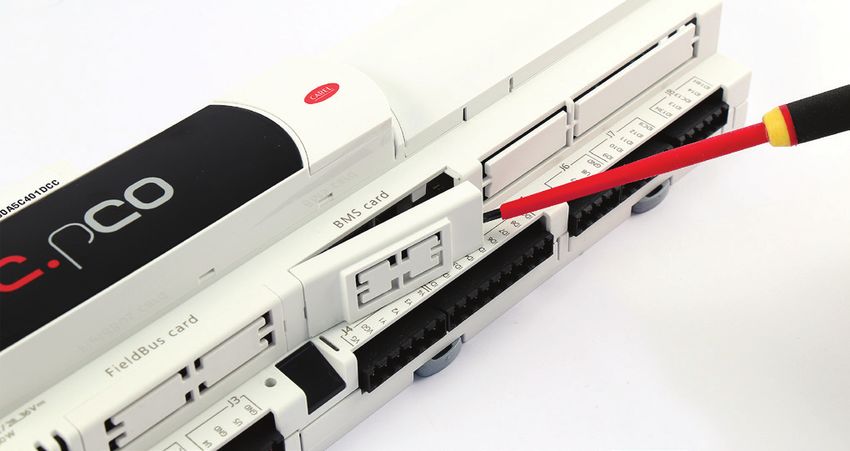
ITA
                                 AVVERTENZE                                                                                        SMALTIMENTO

CAREL basa lo sviluppo dei suoi prodotti su una esperienza pluridecennale nel                      INFORMAZIONE AGLI UTENTI PER IL CORRETTO TRATTAMENTO DEI RIFIUTI
campo HVAC, sull’investimento continuo in innovazione tecnologica di prodotto,                     DI APPARECCHIATURE ELETTRICHE ED ELETTRONICHE (RAEE)
su procedure e processi di qualità rigorosi con test in-circuit e funzionali sul 100%
della sua produzione, sulle più innovative tecnologie di produzione disponibili nel                In riferimento alla Direttiva 2002/96/CE del Parlamento Europeo e del
mercato. CAREL e le sue filiali/affiliate non garantiscono tuttavia che tutti gli aspetti          Consiglio del 27 gennaio 2003 e alle relative normative nazionali di attuazione,
del prodotto e del software incluso nel prodotto risponderanno alle esigenze                       Vi informiamo che:
dell’applicazione finale, pur essendo il prodotto costruito secondo le tecniche dello              •   sussiste l’obbligo di non smaltire i RAEE come rifiuti urbani e di effettuare, per
stato dell’arte.                                                                                       detti rifiuti, una raccolta separata;
Il cliente (costruttore, progettista o installatore dell’equipaggiamento finale) si                •   per lo smaltimento vanno utilizzati i sistemi di raccolta pubblici o privati previsti
assume ogni responsabilità e rischio in relazione alla configurazione del prodotto                     dalla leggi locali. È inoltre possibile riconsegnare al distributore l’apparecchiatura
per il raggiungimento dei risultati previsti in relazione all’installazione e/o                        a fine vita in caso di acquisto di una nuova;
equipaggiamento finale specifico.                                                                  •   questa apparecchiatura può contenere sostanze pericolose: un uso improprio o
CAREL in questo caso, previ accordi specifici, può intervenire come consulente per la                  uno smaltimento non corretto potrebbe avere effetti negativi sulla salute umana
buona riuscita dello start-up macchina finale/applicazione, ma in nessun caso può                      e sull’ambiente;
essere ritenuta responsabile per il buon funzionamento dell’ equipaggiamento/                      •   il simbolo (contenitore di spazzatura su ruote barrato) riportato sul prodotto
impianto finale.                                                                                       o sulla confezione e sul foglio istruzioni indica che l’apparecchiatura è stata
                                                                                                       immessa sul mercato dopo il 13 agosto 2005 e che deve essere oggetto di
Il prodotto CAREL è un prodotto avanzato, il cui funzionamento è specificato nella                     raccolta separata;
documentazione tecnica fornita col prodotto o scaricabile, anche anteriormente                     •   in caso di smaltimento abusivo dei rifiuti elettrici ed elettronici sono previste
all’acquisto, dal sito internet www.carel.com.                                                         sanzioni stabilite dalle vigenti normative locali in materia di smaltimento.
Ogni prodotto CAREL, in relazione al suo avanzato livello tecnologico, necessita di
una fase di qualifica / configurazione / programmazione / commissioning affinché                   Garanzia sui materiali: 2 anni (dalla data di produzione, escluse le parti di
possa funzionare al meglio per l’applicazione specifica. La mancanza di tale fase di               consumo).
studio, come indicata nel manuale, può generare malfunzionamenti nei prodotti
                                                                                                   Omologazioni: la qualità e la sicurezza dei prodotti CAREL S.P.A. sono garantite
finali di cui CAREL non potrà essere ritenuta responsabile.
Soltanto personale qualificato può installare o eseguire interventi di assistenza                  dal sistema di progettazione e produzione certificato ISO 9001.
tecnica sul prodotto.
Il cliente finale deve usare il prodotto solo nelle modalità descritte nella
documentazione relativa al prodotto stesso.

Senza che ciò escluda la doverosa osservanza di ulteriori avvertenze presenti nel
manuale, si evidenza che è in ogni caso necessario, per ciascun Prodotto di CAREL:                                                                       NO POWER
• evitare che i circuiti elettronici si bagnino. La pioggia, l’umidità e tutti i tipi di                                                                  & SIGNAL
  liquidi o la condensa contengono sostanze minerali corrosive che possono                                                                                 CABLES
  danneggiare i circuiti elettronici. In ogni caso il prodotto va usato o stoccato                                                                       TOGETHER
  in ambienti che rispettano i limiti di temperatura ed umidità specificati nel                                              READ CAREFULLY IN THE TEXT!
  manuale;
• non installare il dispositivo in ambienti particolarmente caldi. Temperature
  troppo elevate possono ridurre la durata dei dispositivi elettronici, danneggiarli
                                                                                                       ATTENZIONE: separare quanto più possibile i cavi delle sonde e degli
  e deformare o fondere le parti in plastica. In ogni caso il prodotto va usato o                      ingressi digitali dai cavi dei carichi induttivi e di potenza per evitare
  stoccato in ambienti che rispettano i limiti di temperatura ed umidità specificati                   possibili disturbi elettromagnetici. Non inserire mai nelle stesse canaline
  nel manuale;                                                                                         (comprese quelle dei quadri elettrici) cavi di potenza e cavi di segnale.
• non tentare di aprire il dispositivo in modi diversi da quelli indicati nel manuale;
• non fare cadere, battere o scuotere il dispositivo, poiché i circuiti interni e i
  meccanismi potrebbero subire danni irreparabili;
• non usare prodotti chimici corrosivi, solventi o detergenti aggressivi per pulire
  il dispositivo;
• non utilizzare il prodotto in ambiti applicativi diversi da quanto specificato nel
  manuale tecnico.

Tutti i suggerimenti sopra riportati sono validi altresì per il controllo, schede
seriali, chiavi di programmazione o comunque per qualunque altro accessorio del
portfolio prodotti CAREL.
CAREL adotta una politica di continuo sviluppo. Pertanto CAREL si riserva il diritto
di effettuare modifiche e miglioramenti a qualsiasi prodotto descritto nel presente
documento senza previo preavviso.

I dati tecnici presenti nel manuale possono subire modifiche senza obbligo di
preavviso.

La responsabilità di CAREL in relazione al proprio prodotto è regolata dalle condizioni
generali di contratto CAREL editate nel sito www.carel.com e/o da specifici accordi
con i clienti; in particolare, nella misura consentita dalla normativa applicabile, in
nessun caso CAREL, i suoi dipendenti o le sue filiali/affiliate saranno responsabili
di eventuali mancati guadagni o vendite, perdite di dati e di informazioni, costi
di merci o servizi sostitutivi, danni a cose o persone, interruzioni di attività, o
eventuali danni diretti, indiretti, incidentali, patrimoniali, di copertura, punitivi,
speciali o consequenziali in qualunque modo causati, siano essi contrattuali, extra
contrattuali o dovuti a negligenza o altra responsabilità derivanti dall’installazione,
utilizzo o impossibilità di utilizzo del prodotto, anche se CAREL o le sue filiali/affiliate
siano state avvisate della possibilità di danni.

                                                                                               3                                   KNX serial card +030220326- rel. 1.0 - 16.05.2017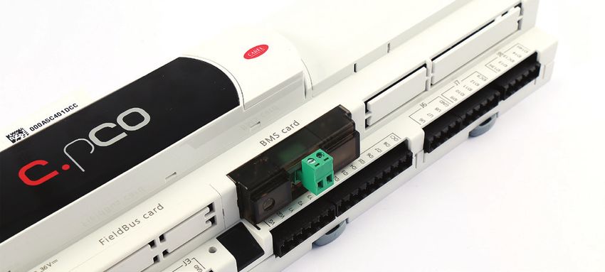
ITA
Indice
1. INTRODUZIONE                                                                                                                              7
 1.1   KNX......................................................................................................................................7
 1.2   Descrizione.....................................................................................................................7
 1.3   Codici.................................................................................................................................7

2. INSTALLAZIONE                                                                                                                             8
 2.1   pCO e c.pCO..................................................................................................................8
 2.2   e-drofan...........................................................................................................................8

3. SPECIFICHE DI COMUNICAZIONE                                                                                                               9
 3.1   Comunicazione KNX................................................................................................9
 3.2   Comunicazione Modbus.......................................................................................9

4. USO DI ETS5                                                                                                                               9

5. USO DEL DCA CAREL                                                                                                                      10
 5.1   Menu “General Settings”......................................................................................10
 5.2   Menu “Datapoints Settings”..............................................................................11
 5.3   Menu “String Tables”...............................................................................................12
 5.4   Assegnazione indirizzo individuale..............................................................13
 5.5   Download configurazione ...............................................................................13

6. IMPOSTAZIONI CONTROLLO                                                                                                                 14
 6.1   Impostazioni applicativo pCO.........................................................................14
 6.2   Impostazioni applicativo c.pCO.....................................................................14
 6.3   Impostazioni controllo e-drofan....................................................................14

7. INTEGRAZIONE CON DISPOSITIVI DI TERZE PARTI 15

8. ALLARMI E SEGNALAZIONI                                                                                                                 15

9. CARATTERISTICHE TECNICHE                                                                                                               16
 9.1   Caratteristiche Tecniche......................................................................................16

                                                                                                                                                    5   KNX serial card +030220326- rel. 1.0 - 16.05.2017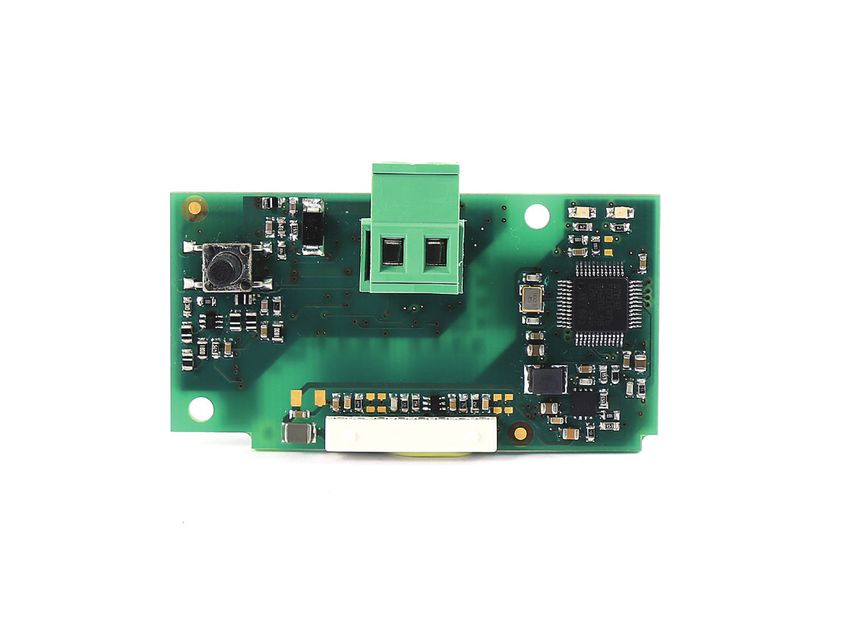
ITA
1. INTRODUZIONE
1.1 KNX
Lo standard tecnologico KNX rappresenta ormai una realtà diffusa
nel settore dell'automazione e controllo di edifici ad uso terziario e
residenziale.
La convergenza tecnologica di EIB con gli altri due standard presenti sul
mercato europeo, BatiBus ed EHS, hanno dato vita al protocollo KNX di
cui EIB rappresenta sostanzialmente la base di riferimento.
Il protocollo KNX è approvato come:
• Standard europeo: CENELEC EN 50090 e CEN EN 13321-1 e 13321-2.
• Standard internazionale: ISO/IEC 14543-3
• Standard Cinese: GB/Z 20965
La scheda seriale KNX è un prodotto certificato KNX.
Per informazioni e supporto tecnico relativo al pacchetto è possibile
contattare l’indirizzo email konnex@carel.com.
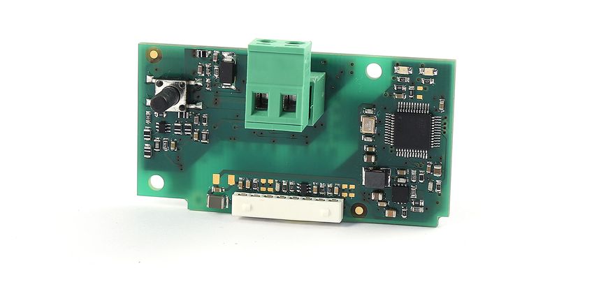
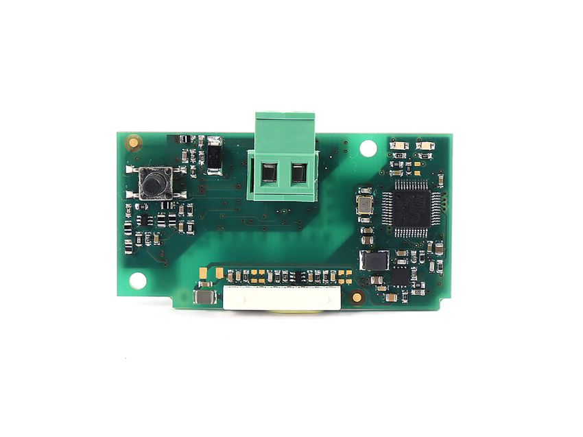
1.2 Descrizione
La scheda KNX si inserisce nella gamma delle schede opzionali per
controlli pCO, c.pCO ed e-drofan. La scheda, dotata di processore ARM
Cortex-M0, svolge la funzione di gateway tra una rete operante secondo il
protocollo KNX/EIB e il protocollo Modbus RTU, direttamente supportato
dal firmware del controllo pCO, dal sistema operativo del controllo c.pCO
e dal firmware del controllo e-drofan.
Per la configurazione ed installazione della scheda è necessario il
programma ETS5 professional, il Device Configuration Apps tool (DCA)
(scaricabili presso l’associazione KNX) e il product database (disponibile
sul sito ksa.carel.com o nel catalogo online).
1.3 Codici
PCOS00KXN0 Modello per la porta pCO BMS, alloggiamento “Serial card”
ed e-drofan.
Push button Red Green
+ -
Fig. 1.a
7 KNX serial card +030220326- rel. 1.0 - 16.05.2017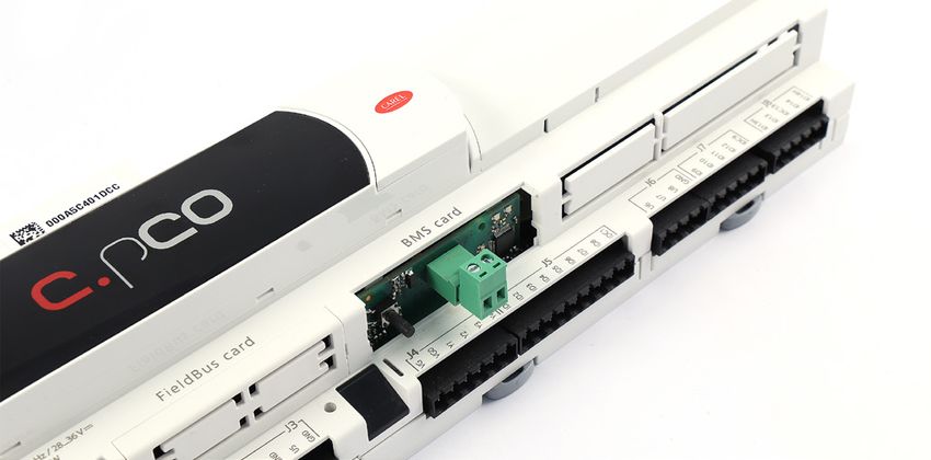
ITA
2. INSTALLAZIONE
2.1 pCO e c.pCO 2.2 e-drofan
Con riferimento alla Fig 2.b-A/B, l’installazione nell’e-drofan si ottiene
a macchina non alimentata, inserendo la scheda opzionale nel
corrispondente connettore, assicurandosi che la scheda sia ben inserita.
(Fig. 2.b, punti A, B). Agganciare ed avvitare il supporto plastico (da
ordinare separatamente, codice PCOS00S030) come da figura 2.b, punti
C e D.
A B
C D
Fig. 2.b
Fig. 2.a
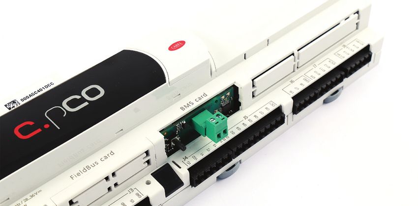
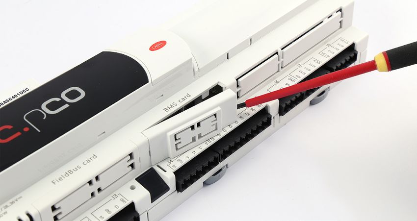
Con riferimento alla Fig. 2.a, l’installazione nel controllo si ottiene a
macchina non alimentata secondo la seguente procedura:
1. Con un cacciavite, togliere lo sportellino “BMS card/serial card”, a
seconda del modello del pCO (vedi Fig. 2.a);
2. Inserire la scheda opzionale nel corrispondente connettore,
assicurandosi che la scheda sia ben inserita e a contatto dei due
appoggi posti sul contenitore del pCO. Attenzione! L’inserimento
della scheda e l’accoppiamento dei connettori potrebbero risultare
difficoltosi a causa dello spazio esiguo e dei due appoggi plastici. Si
consiglia l’inserimento obliquo della scheda e la sua rotazione fino a
far combaciare i connettori.
3. Inserire l’apposito sportellino (da ordinare a parte, cod. PCOS00SKX0)
facendo combaciare il connettore della scheda seriale con il foro
presente sullo sportellino (vedi Fig. 2.a).
KNX serial card +030220326- rel. 1.0 - 16.05.2017 8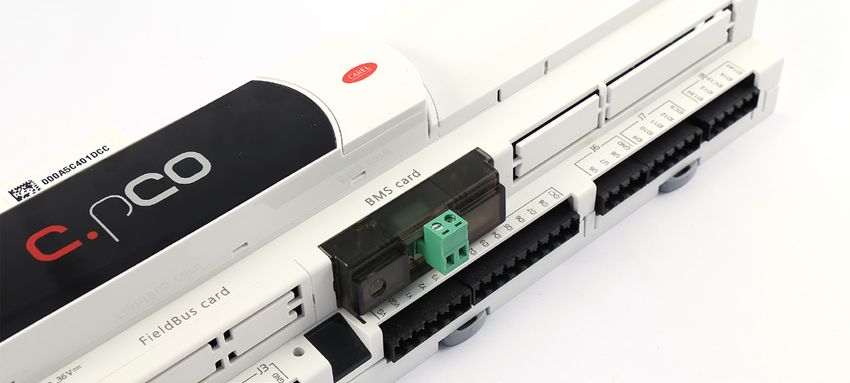
ITA
                                                     3. SPECIFICHE DI COMUNICAZIONE
3.1 Comunicazione KNX                                                                                      3.1.2       Indirizzo dispositivi
La modalità supportata dalla scheda Carel verso KNX è TP1 9.6 kbits/s                                      In una rete KNX ogni dispositivo deve avere un indirizzo univoco.
System mode.                                                                                               L’assegnazione effettiva dell’indirizzo ai dispositivi avviene, tramite
                                                                                                           connessione di rete, utilizzando il software ETS.
Per il funzionamento di un rete KNX è necessario un alimentatore di                                        Con ETS5 si realizza, anche prima di realizzare la connessione al bus,
bus specifico che fornisca al bus una tensione continua pari a 29 Volt.                                    il progetto dell’intero impianto inserendo tutti i dispositivi che lo
La configurazione della rete si realizza utilizzando un personal computer                                  compongono. Il software ETS assegna automaticamente un indirizzo a
(con Windows OS) dove sia installato ETS5, e un’interfaccia tra porta USB/                                 tutti i dispositivi, consentendo, eventualmente, la modifica manuale degli
Ethernet e bus KNX.                                                                                        stessi. I valori degli indirizzi vengono memorizzati nel file del progetto.
                                                                                                           Nella prima fase di installazione, connettendo il personal computer al
                                                                                                           bus, si deve effettuare l’indirizzamento reale dei dispositivi. L’operazione
3.1.1           Datapoint KNX                                                                              si realizza attivando, per ogni dispositivo, la procedura “scarica indirizzo” e
Nello standard KNX il trasferimento dell’informazione tra dispositivi                                      premendo il pulsante sul controllo da configurare. In questo modo ogni
avviene tramite strutture dati dette “datapoints”, il termine “datapoint”                                  dispositivo risulta localizzato ed è possibile procedere alle fasi successive
si può considerare sinonimo di variabile condivisa. Il collegamento                                        della configurazione.
si realizza assegnando ad ogni datapoint un codice numerico detto
“indirizzo di gruppo”, del tutto indipendente dal valore dell’indirizzo di
dispositivo.
Per “condividere” un insieme di variabili tra più dispositivi è necessario,
quindi, che esse abbiano lo stesso indirizzo di gruppo e siano dello stesso
                                                                                                           3.2 Comunicazione Modbus
tipo (bit, byte, word, ecc…). Questo modalità è denominata System                                          Verso il pCO la scheda implementa un master Modbus RTU che utilizza i
mode e di fatto realizza il “free binding” tra le variabili dei vari dispositivi.                          seguenti codici funzione:
La trasmissione dei dati è di tipo multicast: il nodo che ha un determinato                                •   01 Read coil status
datapoint in uscita (flag di tipo trasmissione attivato) invia in rete un                                  •   02 Read discrete inputs
pacchetto che sarà ricevuto contemporaneamente da tutti i dispositivi                                      •   03 Read holding registers
che hanno, in ingresso, un datapoint dello stesso tipo avente lo stesso                                    •   04 Read input registers
indirizzo di gruppo di quello mittente.                                                                    •   05 Force single coil
Esempio di comunicazione tra datapoint:                                                                    •   06 Preset single register.
                     GROUP ADDRESS 1/1/2: shared among device #1and #8                                     L’indirizzo del controllo e il baudrate di comunicazione sono configurabili
                                                                                                           da ETS, tuttavia per il controllo e-drofan l’indirizzo deve necessariamente
                   GROUP ADDRESS 1/1/1: shared among device #1, #4 and #8                                  essere impostato a 1 e il baudrate a 9600 baud. Per gli altri controlli indirizzo
                                                                                                           e baudrate vanno impostati coerentemente con la configurazione scelta.
                                                     GROUP ADDRESS 1/2/3:
                                                     shared among device #4 and #8
1/1/1   1/1/2     1/1/6             1/2/3    1/1/1                            1/2/3    1/1/2   1/1/1

        Device #1                           Device #4                                 Device #8

                                              Fig. 3.a

                                                                                      4. USO DI ETS5
Il programma ETS5® rappresenta la soluzione software per la
progettazione e la messa in servizio di un impianto KNX. ETS5® è un tool
software indipendente dai singoli costruttori ed è commercializzato
dall'Associazione KNX International (www.knx.org). Con ETS5® è possibile
- con un solo tool software - progettare, mettere in servizio ed effettuare
la diagnosi di impianti KNX nei quali siano installati apparecchi di vari
costruttori KNX.
Per l’utilizzo di ETS5 si rimanda al manuale dedicato reperibile sul sito
www.knx.org.

                                                                                                       9                                KNX serial card +030220326- rel. 1.0 - 16.05.2017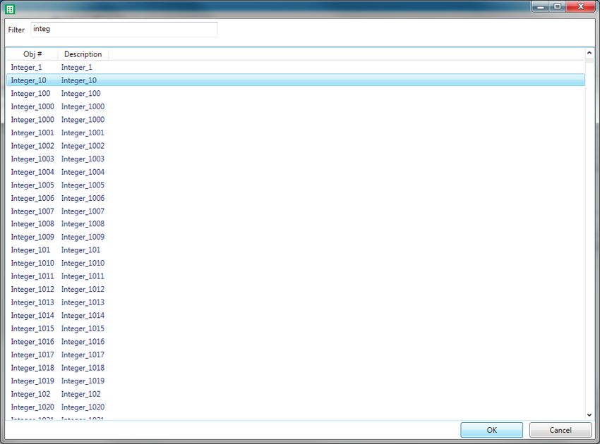
ITA
                                                       5. USO DEL DCA CAREL
 Il tool DCA (Device Configuration Apps) Carel è scaricabile dal sito www.                    Una volta che il tool DCA sia correttamente installato, è necessario
 knx.org. Permette di configurare il gateway Modbus-KNX in base alle                          utilizzare il file in formato knxprod per inserire il nuovo dispositivo nel
 esigenze specifiche dell’utente.                                                             progetto:
 Il tool DCA, scaricato da www.knx.org, può essere installato dalla pagina
 iniziale di ETS, cliccando la voce Apps N active (dove N rappresenta il
 numero di app attive) e cliccando sul tasto '+'.
 E’ possibile verificare la corretta installazione del tool DCA verificando che,
 sia presente e selezionata la dicitura DcaCarel, come in Fig. 5.a.

                                                                                                                                   Fig. 5.b

                                                                                              A questo punto, selezionando il pannello Dispositivi, e importando il
                                                                                              dispositivo, è disponibile il tab DCA che permette di procedere con i
                                                                                              successivi passi di definizione del progetto attraverso la compilazione dei
                                                                                              campi nei tab “General Settings”, “Datapoints Settings” e, opzionale, “String
                                                                                              Tables”.
                                     Fig. 5.a

                                                                                   Fig. 5.c

                                                                                              Nel caso in cui si importi un file 2cf per un controllo della famiglia pCO,
 5.1 Menu “General Settings”                                                                  all’atto dell’importazione il DCA richiede di specificare per quale database
 Dal menu “General Settings” è possibile impostare i parametri di                             parametri sia stata sviluppata l’applicazione:
 comunicazione Modbus tra la scheda e il controllo nel quale è inserita,
 ovvero l’indirizzo di comunicazione (nel range 1-247, con default 1) e il
 baud rate (con default 9600bps). E’ inoltre possibile impostare il massimo
 numero di coil consecutivi che possono essere letti con un singolo
 commando Read Coils (0x01) o Read Discrete Inputs (0x02) e il massimo
 numero di registri consecutivi che possono essere letti con un singolo
 comando Read Holding Registers (0x03) o Read Input Registers (0x04).
 Quando tali parametri sono impostati a 1, le letture multiple sono inibite.
 Nel caso dell’e-drofan, il limite a questi parametri è implicito nel firmware
 del controllo stesso e va impostati manualmente: max multiple regs deve
 valere 1, max multiple coils può essere ignorato dato che e-drofan non
 gestisce coil. Dal medesimo menu è anche possibile impostare alcuni
 parametri di comunicazione KNX:
 • l’intervallo di tempo atteso dalla scheda KNX dal momento in cui rileva                                                         Fig. 5.d
   connessione al bus KNX fino al momento in cui comincia a trasmettere                       L’indicazione della scelta effettuata resta visibile nel menu “General
   pacchetti nel bus stesso (il default è 2s)                                                 Settings”. Per le altre tipologie di controllo, non viene richiesta alcuna
 • il massimo numero di pacchetti che la scheda può trasmettere al                            selezione. Sia il file 2cf che la selezione del database di riferimento non
   secondo (il default a 0 indica che non esiste alcuna limitazione in                        possono essere modificati in corso di configurazione del progetto,
   questo senso).                                                                             infatti importando un nuovo 2cf, una apposita finestra pop-up chiederà
 Una volta completata la configurazione dei parametri di comunicazione,                       conferma di voler effettivamente procedere con l’operazione, rimuovendo
 è necessario importare il file 2cf corrispondente al controllo (o                            tutte le configurazioni precedentemente apportate al progetto.
 all’applicazione a bordo del controllo). Per i controlli della famiglia pCO                  L’operazione di import del file 2cf effettua allo stesso tempo anche
 il file 2cf è un prodotto della compilazione stessa, per i controlli della                   l’import del file 2ct (se presente nella stessa cartella del 2cf ). Tale file può
 famiglia c.pCO può essere esportato da c.design, infine per e-drofan è                       contenere le descrizioni delle variabili tradotte in varie lingue. Il DCA, nel
 scaricabile da ksa.carel.com.                                                                caso di più lingue presenti nel file 2ct, seleziona, se presente, la lingua del
                                                                                              DCA, se questa non è disponibile, seleziona la versione inglese, se anche
                                                                                              questa non è presente, seleziona la prima versione disponibile.

 KNX serial card +030220326- rel. 1.0 - 16.05.2017                                   10
ITA
5.2 Menu “Datapoints Settings”
Accedendo al menu “Datapoints Settings” è possibile associare i parametri
Modbus disponibili nel file 2cf ai datapoint KNX richiesti.
Per aggiungere un datapoint è sufficiente premere il tasto “Add” che
aprirà una finestra di selezione nella quale saranno visibili tutti i parametri
Modbus definiti nel file 2cf (con le relative traduzioni, se presenti, nella
colonna Description). La funzione di filtro consente di facilitare la ricerca
per nome della variabile. Una volta che si sia individuato e selezionato il
parametro di interesse, premendo OK, questo viene aggiunto al menu
Datapoints Settings.
Fig. 5.e
A questo punto, il parametro può essere configurato modificando
opportunamente i campi dei sottomenu “Modbus Datapoint”, “Value
Conversion” e “KNX Datapoint”.
Fig. 5.f
11 KNX serial card +030220326- rel. 1.0 - 16.05.2017ITA
5.2.1 Modbus Datapoint In tutti gli altri casi invece, i campi impostabili sono:
Il sottomenu “Modbus Datapoint” mostra per ogni variabile aggiunta • A, B: permettono di effettuare una trasformazione lineare sul dato. Dato
alcuni dati che non possono essere modificati: il tipo Modbus (holding il valore X del registro Modbus, il valore trasformato è Y = A * X + B.
register, coil, input register, input), l’indirizzo di lettura e di scrittura e il Viceversa, leggendo da KNX il valore modbus viene ottenuto secondo
numero di registri consecutivi che compongono il parametro. Nello stesso la regola X = (Y - B) / A. I valori di default di A e B sono rispettivamente
sottomenu è possibile modificare il campo endianness per specificare 1 e 0 (nessuna trasformazione).
l’ordine dei byte nel parametro Modbus. Il campo prevede la possibilità di • Rounding: metodo di arrotondamento da applicare dopo la
scelta di big o little endianness nel caso in cui il dato di partenza sia a 16 conversione lineare. Il metodo adottato di default è all’intero più vicino.
bit, prevede 4 opzioni (big, little, big swapped, little swapped) per i dati a Altri metodi disponibili sono: up, down, towards 0, away from 0.
32 bit, mentre non è presente per i dati a 1 o 8 bit.
Il default per questo campo è big endian.
5.2.3 KNX Datapoint
Il sottomenu “KNX Datapoint” permette di associare il tipo di datapoint
5.2.2 Value Conversion KNX desiderato scegliendone uno tra quelli disponibili nel menu a
Il sottomenu “Value Conversion” mostra il tipo, non modificabile, del tendina KNX Type.
valore rappresentato dal parametro Modbus (boolean, signed integer, E’ inoltre possibile scegliere la modalità di trasmissione tra una delle 3
unsigned integer, floating), mentre i restanti campi specificano: opzioni seguenti:
• Bit Position: posizione del bit meno significativo nel registro Modbus (a • No send, il datapoint non viene mai trasmesso sul bus KNX
valori compresi tra 0 e numero di bit del registro – 1) autonomamente,
• # of Bits: numero di bit del registro Modbus • On change, il datapoint viene ritrasmesso sul bus KNX ogni volta che
cambia a prescindere dall’entità del cambiamento
Il campo # of Bits mostra la dimensione iniziale del parametro Modbus, • On difference, il datapoint viene ritrasmesso sul bus KNX ogni volta che
questo deve essere ridotto se si desidera modificare il parametro Bit cambia in valore assoluto di più di un certo ammontare, selezionabile
Position ad un valore diverso da 0. La somma del parametro Bit Position nel campo Sending Difference (default 1).
e del nuovo parametro # of Bits deve coincidere con quello di partenza.
E’ anche possibile impostare la modalità di trasmissione ciclica per un
I successivi campi del sottomenu “Value Conversion” dipendono dalla datapoint indicando il periodo in secondi, nel campo Interval (default 1s).
successiva selezione del tipo di datapoint. Se il KNX datapoint selezionato
è il tipo 1.xxx, il menu “Value Conversion” mostra i campi: Speciale attenzione deve essere prestata quando si necessiti di definire un
• Truth value: quando si legge un parametro Modbus X, il datapoint KNX datapoint di tipo 16.xxx character string. In questo caso si deve indicare
Y si ottiene da Y = (X == truth value). Il default per il campo truth value anche quale sia la mapping table associata al datapoint (scelta tra 1 delle
è 1. 8 disponibili). La definizione delle mapping table viene effettuata nel
• Invert boolean: quando impostato a No, non vengono effettuati menu “String Tables”.
ulteriori cambiamenti su Y, al contrario se è Sì, Y viene invertito. Il
default è No.
5.3 Menu “String Tables”
Il menu “String Tables” consente di definire le tabelle di mappamento dei Una volta completata la configurazione di tutti i datapoint, questi
parametri KNX di tipo 16.xxx (character string). La compilazione dei campi risultano disponibili nel menu Devices di ETS ed è quindi possibile
di questo menu pertanto è vincolata alla presenza di datapoint di tipo associare i datapoint ai relativi indirizzi di gruppo seguendo la procedura
16.xxx: in caso non esistano datapoint di questo tipo, si può procedere standard ETS5. Successivamente si può assegnare l’indirizzo individuale
allo step successivo. Per ciascuna delle tabelle referenziate nel menu alla scheda e infine scaricare la configurazione definita nel dispositivo
“Datapoint Settings”, si deve indicare il numero di voci della tabella stessa appena indirizzato.
e per ciascuna voce della tabella si deve mappare il valore del datapoint
nella stringa desiderata.
Fig. 5.g
KNX serial card +030220326- rel. 1.0 - 16.05.2017 12ITA
5.4 Assegnazione indirizzo individuale
L’assegnazione dell’indirizzo individuale della scheda KNX Carel avviene
come da procedura standard.
Assicurarsi che:
• vi sia collegamento al BUS
• il BUS sia alimentato
• la scheda Carel sia collegata alla linea KNX
• il controllo sia alimentato.
Selezionare con il mouse il dispositivo da configurare, tramite il tasto
destro far apparire il menu Download. Selezionare il tasto Download
Individual Address per attivare la procedura di configurazione (Fig. 5.h).
ETS richiede a questo punto di premere il pulsante sulla scheda per
poter procedere con l’operazione. Lo spegnimento del LED verde sulla
scheda conferma l’avvenuta conclusione dell’operazione. Se l’indirizzo
della scheda è già stato configurato appare il messaggio ‘L’indirizzo è già
utilizzato da un altro dispositivo’ (‘The individual address is already in use
by another device’).
Fig. 5.h
5.5 Download configurazione
Assicurarsi che:
• vi sia collegamento al BUS
• il BUS sia alimentato
• la scheda Carel sia collegata alla linea KNX
• il controllo sia alimentato
• Sia stato assegnato l’indirizzo individuale
Selezionare con il mouse il dispositivo da configurare, tramite il tasto
destro far apparire il menu Download. Selezionare il tasto Partial
Download per attivare la procedura di scaricamento della configurazione
(Fig. 5.i).
Fig. 5.i
13 KNX serial card +030220326- rel. 1.0 - 16.05.2017ITA
6. IMPOSTAZIONI CONTROLLO
La scheda KNX Carel, come già detto, svolge la funzione di gateway Inoltre, L’indirizzo delle variabili Modbus si ottiene dall’indice degli atomi
tra il bus KNX e il dispositivo Carel. Il protocollo utilizzato è Modbus supervisore inseriti nell’applicativo pCO nel seguente modo:
quindi il controllo pCO/c.pCO o e-drofan devono essere configurati per
Variabili digitali
operare come slave secondo tale protocollo sulla porta BMS. L’indice
Indirizzo Coil = Indice atomi per variabili digitali
della variabile da scrivere in tabella deve quindi essere coerente con
l’applicativo caricato sul controllo pCO o con la lista di supervisione del Variabili Analogiche
controllo e-drofan. A tal fine, si utilizza il file .2cf che contiene tutte le Indirizzo Registro = Indice atomi per variabili analogiche
informazioni relative al database dei parametri Modbus. Variabili intere
Di seguito si illustrano le procedure di impostazione necessarie sui Indirizzo Registro = Indice atomi per variabili intere + offset (vedi Tab. 6.a).
controlli della famiglia pCO, c.pCO e su e-drofan.
Per completare la configurazione è necessario impostare anche la variabile
BMS_ADDRESS con l’indirizzo della seriale BMS (nel range 1-247) e il baud
rate della seriale agendo sulla variabile di sistema COM_BAUDRATE_BMS
6.1 Impostazioni applicativo pCO secondo la mappa:
Per poter utilizzare la scheda KNX con il pCO, l’applicativo deve COM_BAUDRATE_BMS 0 1 2 3 4
permettere la configurazione del protocollo Modbus Slave sulla seriale Baud rate [bps] 1200 2400 4800 9600 19200
BMS. L’applicativo deve, inoltre, esportare verso supervisore (Modbus)
almeno tutte le variabili (datapoints) richieste lato KNX. Il file .2cf per i controlli della famiglia pCO viene generato all’atto della
Il protocollo Modbus slave è impostabile mediante le variabili di sistema compilazione dell’applicativo da 1tool e viene salvato automaticamente
COM_PROTOCOL_BMS e BMS_EXTENSION, le cui diverse combinazioni nella cartella contenente i binari dell’applicativo.
permettono si disporre di un registro parametri di diversa dimensione
come in Tab. 6.a.
Offset Crosstable
BMS_EXTENSION = 0 128 D:1-199;A:1-127;I:1-127 -> 6.2 Impostazioni applicativo c.pCO
COM_PROTOCOL_BMS = 3 D:1-199;A:1-127;I:129-255
La configurazione del protocollo Modbus slave per i controlli della
BMS_EXTENSION = 1 208 D:1-207;A:1-207;I:1-207 ->
COM_PROTOCOL_BMS = 3 D:1-207;A:1-207;I:209-415 famiglia c.pCO avviene direttamente dal tool c.design. In questo caso gli
COM_PROTOCOL_BMS = 30 5001 D:1-2048;A:1-5000;I:1-5000 -> indirizzi dei registri non necessitano di alcun offset e sono esattamente
D:1-2048;A:1-5000;I:5002-10001 quelli indicati nel Protocol Editor.
BMS_EXTENSION = 0 128 D:1-2048;A:1-127;I:1-10000 -> Indirizzo e baud rate della BMS sono pure direttamente configurabili da
COM_PROTOCOL_BMS = 33 D:1-2048;A:1-127;I:129-10128 c.design.
BMS_EXTENSION = 1 5001 D:1-2048;A:1-5000;I:1-10000 ->
COM_PROTOCOL_BMS = 33 L’esportazione del file 2cf è possibile dalla finestra di configurazione della
D:1-2048;A:1-5000;I:5002-15001
Tab. 6.a linea come mostrato in Fig. 6.a.
Fig. 6.j
6.3 Impostazioni controllo e-drofan
Per gli indirizzi modbus consultare la tabella parametri riportata nel
manuale dell’e-drofan.
Per una corretta comunicazione con la scheda KNX, il controllore e-drofan
deve essere impostato come segue:
Baudrate fisso 9600 Baud
Indirizzo P69=1
Protocollo modbus P54=1
Tab. 6.b
KNX serial card +030220326- rel. 1.0 - 16.05.2017 14ITA
7. ALLARMI E SEGNALAZIONI
Led Significato Errore/rimedi
Rosso Acceso fisso Errore assenza comunicazione modbus tra scheda KNX e pCO Configurazione:
• Indirizzo pCO o e-drofan errato
• Baudrate pCO non corretto
• protocollo pCO o e-drofan errato
Lampeggiante Errore comunicazione modbus tra scheda KNX e pCO/ e-drofan Modbus exception:
• la scheda è stata configurata con indirizzi
modbus errati o non supportati
Verde Acceso fisso È stato premuto il tasto per l’assegnazione dell’indirizzo e la scheda è
in attesa che da ETS, si proceda con la relativa procedura
Lampeggiante veloce • Non è stata caricata la configurazione Scaricare la configurazione da ETS
• Un lampeggio veloce breve indica la ricezione dell’indirizzo dopo
la pressione del tasto
Lampeggiante lento Configurazione in corso: ETS sta effettuando il download della
configurazione
Verde + Rosso Accesi entrambi fissi Mancanza alimentazione Bus KNX Verificare: alimentatore bus KNX, collegamenti
elettrici e polarità connessioni ai morsetti
+ e - del connettore.
Lampeggianti Aggiornamento del FW della board in corso
alternativamente
Tab. 7.a
15 KNX serial card +030220326- rel. 1.0 - 16.05.2017ITA
8. CARATTERISTICHE TECNICHE
8.1 Caratteristiche Tecniche
Alimentazione 12 ÷ 33 V da scheda controllo
Potenza assorbita: max 200 mW
Alimentazione BUS 21÷32V Corrente assorbita: 5 mA
BUS TP1 9600 baud
Numero massimo datapoints 250
Morsetti a vite Sezione conduttori min. 0,2 mm max. 1,5 mm2 - 30 – 12 AWG
Isolamento Bus TP Optoisolato dalla massa del controllo
Grado di protezione IP00
Condizioni di funzionamento -20T60 °C, umiditàENG
WARNINGS DISPOSAL
CAREL bases the development of its products on decades of experience in HVAC, INFORMATION FOR USERS ON THE CORRECT HANDLING OF WASTE
on continuous investments in technological innovations to products, procedures ELECTRICAL AND ELECTRONIC EQUIPMENT (WEEE)
and strict quality processes with in-circuit and functional testing on 100% of its
products, and on the most innovative production technology available on the In reference to European Union directive 2002/96/EC issued on 27 January
market. CAREL and its subsidiaries/affiliates nonetheless cannot guarantee that all 2003 and related national legislation, please note that:
the aspects of the product and the software included with the product respond • WEEE cannot be disposed of as municipal waste and such waste must be
to the requirements of the final application, despite the product being developed collected and disposed of separately;
according to start-of-the-art techniques. • the public or private waste collection systems defined by local legislation must
The customer (manufacturer, developer or installer of the final equipment) accepts be used. In addition, the equipment can be returned to the distributor at the
all liability and risk relating to the configuration of the product in order to reach end of its working life when buying new equipment;
the expected results in relation to the specific final installation and/or equipment. • the equipment may contain hazardous substances: the improper use or
CAREL may, based on specific agreements, acts as a consultant for the positive incorrect disposal of such may have negative effects on human health and on
commissioning of the final unit/application, however in no case does it accept the environment;
liability for the correct operation of the final equipment/system. • the symbol (crossed-out wheeled bin) shown on the product or on the
packaging and on the instruction sheet indicates that the equipment has been
The CAREL product is a state-of-the-art product, whose operation is specified in the introduced onto the market after 13 August 2005 and that it must be disposed
technical documentation supplied with the product or can be downloaded, even of separately;
prior to purchase, from the website www.carel.com. • in the event of illegal disposal of electrical and electronic waste, the penalties are
Each CAREL product, in relation to its advanced level of technology, requires setup/ specified by local waste disposal legislation.
configuration/programming/commissioning to be able to operate in the best
possible way for the specific application. The failure to complete such operations, Warranty on materials: 2 years (from production date, excluding
which are required/indicated in the user manual, may cause the final product to consumables).
malfunction; CAREL accepts no liability in such cases.
Approval: the quality and safety of CAREL S.P.A. products are guaranteed by
Only qualified personnel may install or carry out technical service on the product.
the ISO 9001 certified design and production system.
The customer must only use the product in the manner described in the
documentation relating to the product.
In addition to observing any further warnings described in this manual, the
following warnings must be heeded for all CAREL products:
• prevent the electronic circuits from getting wet. Rain, humidity and all types of
liquids or condensate contain corrosive minerals that may damage the electronic NO POWER
circuits. In any case, the product should be used or stored in environments that & SIGNAL
comply with the temperature and humidity limits specified in the manual; CABLES
• do not install the device in particularly hot environments. Too high temperatures TOGETHER
may reduce the life of electronic devices, damage them and deform or melt the READ CAREFULLY IN THE TEXT!
plastic parts. In any case, the product should be used or stored in environments
that comply with the temperature and humidity limits specified in the manual;
IMPORTANT: separate as much as possible the probe and digital input
• do not attempt to open the device in any way other than described in the
manual.
cables from cables to inductive loads and power cables, so as to avoid
• do not drop, hit or shake the device, as the internal circuits and mechanisms may possible electromagnetic disturbance. Never run power cables (including
be irreparably damaged; the electrical panel cables) and signal cables in the same conduits.
• do not use corrosive chemicals, solvents or aggressive detergents to clean the
device.
• do not use the product for applications other than those specified in the
technical manual.
All of the above suggestions likewise apply to the controllers, serial cards,
programming keys or any other accessory in the CAREL product portfolio.
CAREL adopts a policy of continual development. Consequently, CAREL reserves
the right to make changes and improvements to any product described in this
document without prior warning.
The technical specifications shown in the manual may be changed without prior
warning.
The liability of CAREL in relation to its products is specified in the CAREL general
contract conditions, available on the website www.CAREL.com and/or by specific
agreements with customers; specifically, to the extent where allowed by applicable
legislation, in no case will CAREL, its employees or subsidiaries/affiliates be liable
for any lost earnings or sales, losses of data and information, costs of replacement
goods or services, damage to things or people, downtime or any direct, indirect,
incidental, actual, punitive, exemplary, special or consequential damage of any
kind whatsoever, whether contractual, extra-contractual or due to negligence, or
any other liabilities deriving from the installation, use or impossibility to use the
product, even if CAREL or its subsidiaries/affiliates are warned of the possibility of
such damage.
3 KNX serial card +030220326- rel. 1.0 - 16.05.2017ENG
Content
1. INTRODUCTION 7
1.1 KNX......................................................................................................................................7
1.2 Description.....................................................................................................................7
1.3 Part numbers................................................................................................................7
2. INSTALLATION 8
2.1 pCO and c.pCO............................................................................................................8
2.2 e-drofan...........................................................................................................................8
3. COMMUNICATION SPECIFICATIONS 9
3.1 KNX communication................................................................................................9
3.2 Modbus communication......................................................................................9
4. USING ETS5 9
5. USING THE CAREL DCA 10
5.1 “General Settings” menu.....................................................................................10
5.2 “Datapoints Settings” menu..............................................................................11
5.3 “String Tables” menu..............................................................................................12
5.4 Assigning an individual address....................................................................13
5.5 Download the configuration ..........................................................................13
6. CONTROLLER SETTINGS 14
6.1 pCO application settings....................................................................................14
6.2 c.pCO application settings................................................................................14
7. ALARMS AND SIGNALS 15
8. TECHNICAL SPECIFICATIONS 16
8.1 Technical specifications.......................................................................................16
5 KNX serial card +030220326- rel. 1.0 - 16.05.2017ENG
1. INTRODUCTION
1.1 KNX
The KNX technological standard is now widely used in building
automation and control for commercial and residential applications.
The technological convergence of EIB with two other standards used on
the European market, BatiBus and EHS, led to the establishment of the
KNX protocol, in which EIB essentially represents the reference basis.
The protocol KNX is approved as:
• European standard: CENELEC EN 50090 and CEN EN 13321-1 and
13321-2.
• International standard: ISO/IEC 14543-3
• Chinese standard: GB/Z 20965
The KNX serial card is a KNX-certified product.
For information and technical support regarding this package, please
contact us by email at konnex@carel.com.
1.2 Description
The KNX card is part of the range of optional cards for pCO, c.pCO
and e-drofan controllers. The card, equipped with an ARM Cortex-M0
processor, acts as a gateway between a network operating according to
the KNX/EIB protocol and the Modbus RTU protocol, supported directly
by the firmware on pCO controller, the operating system on the c.pCO
controller and the firmware on the e-drofan controller.
To configure and install the card, the following are required: ETS5
professional program, Device Configuration Apps tool (DCA)
(downloadable from KNX) and the product database (available at ksa.
carel.com or the online catalogue).
1.3 Part numbers
PCOS00KXN0 model for pCO BMS port, “Serial card” socket and e-drofan.
Push button Red Green
+ -
Fig. 1.a
7 KNX serial card +030220326- rel. 1.0 - 16.05.2017ENG
2. INSTALLATION
2.1 pCO and c.pCO 2.2 e-drofan
With reference to Fig 2.b-A/B, the optional card is installed on the e-drofan
controller when powered off, inserting it correctly in the corresponding
slot. (Fig. 2.b, points A, B). Fit and tighten the plastic support (to be ordered
separately, P/N PCOS00S030) as shown in Figure 2.b, points C and D.
A B
C D
Fig. 2.b
Fig. 2.a
With reference to Fig. 2.a, the card is installed on the controller when
powered off, with following procedure:
1. Use a screwdriver to remove the “BMS card/serial card” cover,
depending on the model of the pCO (see Fig. 2.a);
2. Insert the optional card in the corresponding slot, making sure that
the card is fitted correctly and in contact with the two supports on
the case of the pCO. Warning! The card and the connectors may
be hard to install due to the space available and the two plastic
supports; the card should be inserted obliquely, and then rotated
until the connectors are aligned.
3. Fit the special cover (ordered separately, P/N PCOS00SKX0) lining up
the connector on the serial card with the hole provided on the cover
(see Fig. 2.a).
KNX serial card +030220326- rel. 1.0 - 16.05.2017 8ENG
3. COMMUNICATION SPECIFICATIONS
3.1 KNX communication 3.1.2 Device addresses
The mode supported by the Carel Konnex card is TP1 9.6 kbits/s System In a KNX network, each device must have a unique address. The addresses
mode. are assigned to the devices over the network connection using the ETS
software.
Operation of a KNX network requires a specific bus power supply that ETS5 is used to define, even before connecting to the bus, the layout
supplies the bus 29 volts DC. The network is configured using a personal of the entire system, adding all the devices that make it up. The ETS
computer (Windows OS) running the ETS5 program, and an interface software automatically assigns an address to each device, however
between the USB/Ethernet port and the KNX bus. where necessary these can be changed manually. The values of the
addresses are saved in a project file. During the first stage of installation,
when connecting the personal computer to the bus, the actual device
3.1.1 KNX datapoint addresses need to be set. This operation is performed by activating the
In the KNX standard, information is transferred between devices via data “download address” procedure for each device and then pressing the
structures called “datapoints”; the term “datapoint” can be considered a button on the controller being configured. In this way, each device is
synonym of shared variable. The connection is created by assigning the identified and configuration can continue.
“group address” to each datapoint, independently of the device address.
To “share” a set of variables between multiple devices, these must have the
same group address and be the same type (bit, byte, word, etc.…). This
mode is called System mode and in fact creates “free binding” between
the variables on the various devices.
3.2 Modbus communication
Multicast data transmission is used: the node that has a certain output The card acts as a Modbus RTU master in relation to the pCO, using the
datapoint (transmission flag activated) sends the network a packet following function codes:
that will be received at the same time by all the devices with an input • 01 Read coil status
datapoint of the same type, with the same group address as the sender. • 02 Read discrete inputs
Example of communication between datapoints: • 03 Read holding registers
GROUP ADDRESS 1/1/2: shared among device #1and #8
• 04 Read input registers
• 05 Force single coil
• 06 Preset single register.
GROUP ADDRESS 1/1/1: shared among device #1, #4 and #8
The controller address and baud rate can be configured using the ETS
software. For the e-drofan controller the address must be set to 1 and the
GROUP ADDRESS 1/2/3:
shared among device #4 and #8 baud rate must be 9600 baud. For the other controllers, the address and
1/1/1 1/1/2 1/1/6 1/2/3 1/1/1 1/2/3 1/1/2 1/1/1 baud rate must be set in line with the chosen configuration.
Device #1 Device #4 Device #8
Fig. 3.a
4. USING ETS5
The ETS5® program is the software solution for designing and setting up
a KNX system. ETS5® is a software tool that is independent of individual
manufacturers and is marketed by KNX International (www.knx.org).
ETS5® can be used to design, commission and run diagnostics on KNX
systems installed with KNX devices made by different manufacturers.
For information on how to the use ETS5, see the dedicated manual
available at www.knx.org.
9 KNX serial card +030220326- rel. 1.0 - 16.05.2017ENG
5. USING THE CAREL DCA
The Carel DCA (Device Configuration Apps) tool can be downloaded Once the DCA tool has been correctly installed, the file in knxprod format
from www.knx.org. This is used to configure the Modbus-KNX gateway must be used to add the new device to the project:
based on the user’s specific requirements.
The DCA tool, downloaded from www.knx.org, can be installed from
the ETS opening page, clicking Apps N active (where N represents the
number of active apps) and then clicking the '+' button.
Correct installation of the DCA tool can be verified by checking that
DcaCarel is displayed and selected, as shown in Fig. 5.a.
Fig. 5.b
Then, selecting the Devices panel and importing the device, a DCA
tab is provided, used to continue the steps for defining the project by
completing the fields in the “General Settings”, “Datapoints Settings” and,
optionally, “String Tables” tabs.
Fig. 5.a
Fig. 5.c
When importing a 2cf file for a pCO family controller, the DCA requires
5.1 “General Settings” menu the name of the parameter database that the application has been
The “General Settings” menu is used to set the Modbus communication developed for:
parameters between the card and the corresponding controller, i.e. the
communication address (in the range 1-247, default 1) and baud rate
(default 9600bps). The maximum number of consecutive coils read with
an individual Read Coils (0x01) or Read Discrete Inputs (0x02) command,
and the maximum number of consecutive registers read with an
individual Read Holding Registers (0x03) or Read Input Registers (0x04)
command can also be set. When these parameters are set to 1, multiple
readings are disabled. For the e-drofan, the limit to these parameters is
implicit in the controller’s firmware and should be set manually: max
multiple regs must be 1, max multiple coils can be ignored, given that
e-drofan does not manage coils. The same menu can be used to set some
KNX communication parameters:
• the time interval expected by the KNX card from the moment it detects
a connection to the KNX bus until the moment it starts sending packets Fig. 5.d
to the bus (default 2s) The selected database is shown in the “General Settings” menu. For the
• the maximum number of packets that the card can send per second other controllers this option does not need to be selected. The 2cf file and
(the default is 0, indicating no limits). the selected reference database cannot be modified when configuring
Once the communication parameters have been set, the 2cf file the project; indeed if importing a new 2cf, a pop-up message will prompt
corresponding to the controller (or the application on the controller) for confirmation before proceeding, warning that all configurations
needs to be imported. For the pCO family controllers, the 2cf file is previously made to the project will be deleted.
self-compiled, for the c.pCO family controllers it can be exported from The 2cf file is imported together with the 2ct file (if present in the same
c.design, while for e-drofan it can be downloaded from ksa.carel.com. directory as the 2cf ). This file contains descriptions of the variables
translated into different languages. If there are multiple languages in the
2ct file, the same language as the DCA is selected; if this is not available,
the English version is selected, and if this too is not available, the first
available version is selected.
KNX serial card +030220326- rel. 1.0 - 16.05.2017 10ENG
5.2 “Datapoints Settings” menu
The “Datapoints Settings” menu is used to associate the Modbus
parameter in the 2cf file with the required KNX datapoints.
To add a datapoint, simply click “Add”: a selection window will be
displayed, containing all the Modbus parameters defined in the 2cf
file (with the corresponding translations, if available, in the Description
column). The filter function can be used to refine the search by variable
name. Once the desired parameter has been identified and selected, click
OK to add it to the Datapoints Settings menu.
Fig. 5.e
The selected parameter can then be configured by suitably setting the
fields in the “Modbus Datapoint”, “Value Conversion” and “KNX Datapoint”
sub-menus.
Fig. 5.f
11 KNX serial card +030220326- rel. 1.0 - 16.05.2017ENG
5.2.1 Modbus Datapoint In all other cases, the following fields can be set:
For each variable that has been added, the “Modbus Datapoint” sub- • A, B: allow linear conversion on the data. With the value of the Modbus
menu shows certain data that cannot be modified: Modbus type (holding register being X, the converted value Y = A * X + B. Vice-versa, if
register, coil, input register, input), read/write address, and the number of reading from KNX, the Modbus value is determined using the rule X
consecutive registers making up the parameter. In the same sub-menu, = (Y - B) / A. The default values of A and B are 1 and 0 respectively (no
the endianness field can be set so as to specify the order of bytes in the transformation).
Modbus parameter. The options are big or little endianness for 16-bit • Rounding: method for rounding off the result of linear conversion.
data, there are four options (big, little, big swapped, little swapped) for The method adopted by default is the nearest whole number. Other
32-bit data, while no options can be selected for 1- or 8-bit data. methods available are: up, down, towards 0, away from 0.
The default value for this field is big endian.
5.2.3 KNX Datapoint
5.2.2 Value Conversion The “KNX Datapoint” sub-menu is used to associate the type of KNX
The “Value Conversion” sub-menu shows the type (non-modifiable) of datapoint, choosing from the available options in the KNX Type drop-
value represented by the Modbus parameter (Boolean, signed integer, down menu.
unsigned integer, floating), while the remaining fields specify: The transmission mode can also be selected, from one of the following
• Bit Position: position of the least significant bit in the Modbus register three options:
(values between 0 and number of bits in the register – 1) • No send, the datapoint is not never sent independently over the KNX
• # of Bits: number of bits in the Modbus register bus,
• On change, the datapoint is sent again over the KNX bus whenever it
The # of Bits field shows the initial size of the Modbus parameter, this changes, irrespective of the extent of the change
must be decreased if setting the Bit Position parameter to a value other • On difference, the datapoint is sent again over the KNX bus whenever
than 0. The sum of the Bit Position parameter and the new # of Bits setting it changes by absolute value more than a certain amount, selectable in
must coincide with the initial value. the Sending Difference field (default 1).
The other fields in the “Value Conversion” sub-menu depend on the type Cyclical transmission mode can also be selected for a datapoint,
of datapoint selected subsequently. If the selected KNX datapoint is type specifying the period in seconds, in the Interval field (default 1s).
1.xxx, the “Value Conversion” sub-menu shows the following fields:
• Truth value: when reading Modbus parameter X, the KNX datapoint Y Special attention must be paid when needing to define a 16.xxx
will be: Y = (X == truth value). The default for the truth value is 1. character string datapoint. In this case, the mapping table associated
• Invert boolean: when set to No, no other changes are made to Y, with the datapoint also needs to be specified (choice between 1 of the 8
otherwise when set to Yes, Y is inverted. The default is No. available). The mapping table is defined in the “String Tables” menu.
5.3 “String Tables” menu
The “String Tables” menu is used to define the mapping tables for Once all of the datapoints have been configured, these are available in
type 16.xxx KNX parameters (character strings). The fields in this menu the ETS Devices menu; the datapoints can then be associated with the
therefore depend on whether there is a type 16.xxx datapoint: if there corresponding group addresses, following the standard procedure in
are no datapoints of this type, proceed with the next step. For each of ETS5. Subsequently, the individual address can be assigned to the card
the tables referred to in the “Datapoint Settings” menu, the number of and the configuration for the corresponding device can be downloaded.
items in the table needs to be specified, and for each item in the table the
datapoint value needs to be mapped to the required string.
Fig. 5.g
KNX serial card +030220326- rel. 1.0 - 16.05.2017 12Puoi anche leggere