UPS Remote PANEL - Manuale d'uso - User manual
←
→
Trascrizione del contenuto della pagina
Se il tuo browser non visualizza correttamente la pagina, ti preghiamo di leggere il contenuto della pagina quaggiù
UPS
Remote PANEL

 - Manuale d’uso -
  - User manual -
- ITALIANO -
INTRODUZIONE
Vi ringraziamo per la scelta del nostro prodotto.
La nostra azienda è specializzata nella progettazione, nello sviluppo e nella produzione di gruppi
statici di continuità (UPS).
L’accessorio descritto in questo manuale è un prodotto di alta qualità, attentamente progettato e
costruito allo scopo di garantire le migliori prestazioni.
Questo manuale contiene le istruzioni dettagliate per l’uso e l’installazione del prodotto.
Per informazioni sull’utilizzo e per ottenere il massimo delle prestazioni dalla Vostra
apparecchiatura, il presente manuale dovrà essere conservato con cura vicino
all’accessorio e CONSULTATO PRIMA DI OPERARE SULLO STESSO.
SICUREZZA
Questa parte del manuale contiene precauzioni da seguire scrupolosamente in quanto
riguardano la SICUREZZA.
Il dispositivo è stato realizzato per l’uso professionale e quindi non è adatto per l’uso in
ambiente domestico.
Il dispositivo è stato progettato per funzionare soltanto in ambienti chiusi. È bene installarlo
in ambienti privi di liquidi infiammabili, gas o altre sostanze nocive.
Evitare che acqua, liquidi in genere e/o altri oggetti estranei entrino nel dispositivo.
In caso di guasto e/o di cattivo funzionamento dell’apparecchio astenersi da qualsiasi
tentativo di riparazione e rivolgersi esclusivamente al centro assistenza.
Questo apparecchio dovrà essere destinato solo all’uso per il quale è stato espressamente
concepito. Ogni altro uso è da considerarsi improprio e quindi pericoloso. Il costruttore non
può essere considerato responsabile per eventuali danni causati da usi impropri, erronei ed
irragionevoli.
© E’ vietata la riproduzione di qualsiasi parte del presente manuale anche se parziale salvo autorizzazione della ditta
costruttrice.
Per scopi migliorativi, il costruttore si riserva la facoltà di modificare il prodotto descritto in qualsiasi momento e
senza preavviso.
-1-- ITALIANO -
INDICE
VERIFICA DEL CONTENUTO DELL’IMBALLO 3
MONTAGGIO SUPPORTO DA TAVOLA 3
DESCRIZIONE 4
SCHEMA DI COLLEGAMENTO CON L’UPS 6
REALIZZAZIONE DEL CAVO DI COLLEGAMENTO CON L’UPS 7
SPECIFICHE CAVO 7
COLLEGAMENTI POSSIBILI 7
CONNETTORI E DIP-SWITCH 8
CONFIGURAZIONE 10
CONFIGURAZIONE TRAMITE DIP-SWITCH 10
CONFIGURAZIONE TRAMITE SOFTWARE 10
PROTOCOLLO MODBUS-JBUS 11
FUNZIONI SUPPORTATE 11
TABELLE DEGLI STATI, MISURE, VALORI NOMINALI E COMANDI 11
CODICI COMANDI 14
TABELLA DATI TECNICI 15
-2-- ITALIANO -
VERIFICA DEL CONTENUTO DELL’IMBALLO
Nell’imballo sono presenti:
Pannello Remoto Supporto da tavolo
Alimentatore Cavo seriale PIN to PIN
MONTAGGIO SUPPORTO DA TAVOLA
Se si desidera utilizzare il Pannello Remoto con il suo supporto, montarlo come illustrato di seguito
utilizzando le viti in dotazione.
-3-- ITALIANO -
DESCRIZIONE
Il Pannello Remoto consente di monitorare a distanza l’UPS e di avere sempre in tempo reale una
panoramica dettagliata dello stato della macchina. Tramite questo dispositivo è possibile
consultare le misure elettriche di rete, uscita, batteria, ecc.* e rilevare eventuali malfunzionamenti.
* Per la precisione delle misure fare riferimento al manuale dell’UPS.
L’indicazione del tempo di autonomia residua è una STIMA; non è da considerarsi quindi uno strumento di misura
assoluto.
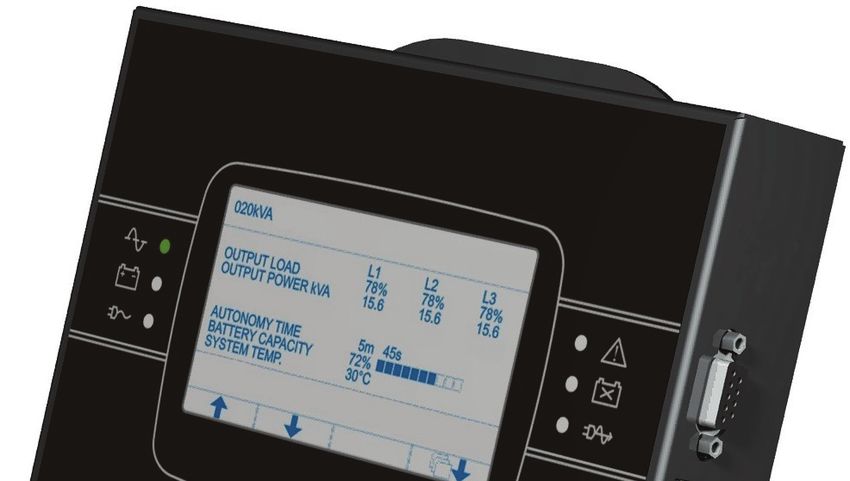
LED funzionamento da rete LED batterie da sostituire
LED funzionamento da batteria LED modalità ECO
LED carico su bypass Display grafico
LED stand-by / allarme
F1, F2, F3, F4 = TASTI FUNZIONE. La funzione di ogni tasto è indicata nella parte inferiore
del display e varia a seconda del menu.
-4-- ITALIANO -
Il display è suddiviso in quattro zone principali, ognuna con un suo ruolo specifico.
Videate di esempio del display grafico
(videate a scopo dimostrativo, la situazione raffigurata potrebbe differire dalla realtà)
Zona del display dove vengono visualizzate a seconda della
INFORMAZIONI
schermata, modello della macchina oppure titolo del menu attivo in
GENERALI
quel momento.
Zona principale del display adibita alla visualizzazione delle misure
VISUALIZZAZIONE
dell’UPS (costantemente aggiornate in tempo reale), e alla
DATI / NAVIGAZIONE
consultazione dei menu selezionabili dall’utente tramite gli appositi
MENU
tasti funzione.
ERRORI - GUASTI Zona di visualizzazione di eventuali errori e/o guasti dell’UPS.
Zona divisa in quattro caselle, ognuna relativa al tasto funzione
sottostante. A seconda del menu attivo in quel momento, il display
FUNZIONE TASTI
visualizza nell’apposita casella la funzione adibita al tasto
corrispondente.
Simbologia dei tasti
Per entrare nel menu principale
Per ritornare al menu o visualizzazione precedente
Per scorrere le varie voci selezionabili all’interno di un menu o passare da una
pagina all’altra durante una visualizzazione dati
Per confermare una selezione
Per tacitare temporaneamente il buzzer (tenere premuto per più di 0.5 sec.).
-5-- ITALIANO -
SCHEMA DI COLLEGAMENTO CON L’UPS
Solo con alcuni modelli di UPS è possibile non utilizzare l’alimentatore in
dotazione e alimentare il dispositivo tramite la porta seriale dell’UPS.
In questo caso, l’UPS deve garantire un’alimentazione di +15V ± 5% sulla porta
seriale (fare riferimento al manuale dell’UPS).
-6-- ITALIANO -
REALIZZAZIONE DEL CAVO DI COLLEGAMENTO CON L’UPS
Il Pannello Remoto comunica tramite linea seriale con l’UPS. Il cavo per collegare il dispositivo alla
macchina deve soddisfare le specifiche seguenti:
SPECIFICHE CAVO
cavo multipolare a 5 fili (AWG22 – AWG28) schermato con capacità max 250 pF/m *.
Lunghezza max consigliata
50 m → 9600 baud
300m → 1200 baud
* Per cavi con capacità superiori non sono garantite le velocità riportate in tabella.
COLLEGAMENTI POSSIBILI
UPS Pannello Remoto
DB-9 femmina DB-9 maschio
2 2
3 3
5 5
7 7
8 (1) 8 (1)
(1)
Collegare solo se l’UPS fornisce un’alimentazione di +15V ± 5% su questo PIN (fare riferimento al
manuale dell’UPS)
UPS Pannello Remoto
DB-9 maschio DB-9 maschio
2 3
3 2
5 5
-7-- ITALIANO -
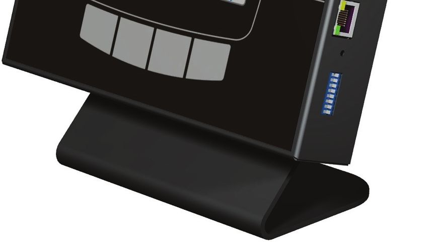
CONNETTORI E DIP-SWITCH
Ai lati del dispositivo sono presenti alcuni connettori ed un dip-switch. Di seguito vengono illustrate
le loro caratteristiche:
UPS SERIAL: porta seriale per il collegamento del dispositivo con l’UPS
SERIAL 1: porta di comunicazione RS232 per monitorare l’UPS tramite protocollo proprietario
GPSER
+12Vdc: Connettore di alimentazione; collegare l’alimentatore fornito con il dispositivo (o
equivalente) a questo connettore.
UPS SERIAL SERIAL 1
1 2 3 4 5 1 2 3 4 5
6 7 8 9 6 7 8 9
PIN # SEGNALE PIN # SEGNALE
1 n.c. 1 n.c.
2 RXD 2 RXD
3 TXD 3 TXD
4 n.c. 4 +12Vdc OUT (1)
5 GND 5 GND
6 n.c. 6 n.c.
7 +12Vdc OUT (1) 7 +12Vdc OUT (1)
8 +15Vdc IN 8 n.c.
9 n.c. 9 n.c.
n.c.: non connesso
(1)
corrente massima totale su tutte le uscite: 50 mA
Non utilizzare se il dispositivo viene alimentato tramite la porta seriale dell’UPS
-8-- ITALIANO -
SERIAL 2: porta di comunicazione RS485 half-duplex per monitorare l’UPS tramite protocollo
MODBUS/JBUS RTU. La porta può essere configurata nelle modalità seguenti:
Baud Rate [bps] Parità Bit di stop
1200 Nessuna
2400 1
4800 Pari
9600 2
19200 Dispari
NOTA: i valori riportati in grassetto indicano la configurazione di default.
SERIAL 3: porta di comunicazione RS232 per monitorare l’UPS tramite protocollo proprietario
GPSER
SERIAL 2 SERIAL 3
PIN # SEGNALE PIN # SEGNALE
1 RXTX+ 1 n.u.
2 RXTX- 2 TXD
3 n.c. 3 RXD
4 ≡ PIN 2 4 n.c.
5 ≡ PIN 1 5 GND
6 n.c. 6 +12Vdc OUT (1)
7 +5Vdc OUT (max 10mA) 7 n.c.
8 GND 8 n.u.
9 n.u.
n.c.: non connesso n.u.: non utilizzare
(1)
corrente massima totale su tutte le uscite: 50 mA
Non utilizzare se il dispositivo viene alimentato tramite la porta seriale dell’UPS
-9-- ITALIANO -
CONFIGURAZIONE
Il dispositivo può essere configurato in due modi:
¾ tramite dip-switch: per una configurazione rapida delle impostazioni base
¾ tramite software: per una configurazione completa di tutti i parametri
In entrambi i casi, per rendere effettiva la configurazione scelta è necessario resettare (tramite
apposito pulsante) o disalimentare l’accessorio.
CONFIGURAZIONE TRAMITE DIP-SWITCH
DIP-SWITCH
Posizione Stato Descrizione
OFF Configurazione tramite software
8
ON Configurazione tramite dip-switch
OFF Rt non inserita *
6
ON Rt inserita *
OFF Protocollo dell’UPS: GPSER (PRTK: GPSER1...)
5
ON Protocollo dell’UPS: SENTR (PRTK: SENTR1...)
OFF Baud rate dell’UPS: 1200 baud
4
ON Baud rate dell’UPS: 9600 baud
OFF Baud rate della porta SERIAL 2: 9600 baud
3
ON Baud rate della porta SERIAL 2: 19200 baud
* il dispositivo viene fornito con la resistenza di terminazione del bus RS485 già montata al suo interno
(Rt = 120Ω)
Per configurare l’indirizzo MODBUS del dispositivo, impostare il dip-switch come descritto nella
tabella seguente:
DIP-SWITCH
Posizione 2 Posizione 1 Indirizzo
OFF ON 1
ON OFF 2
ON ON 3
CONFIGURAZIONE TRAMITE SOFTWARE
Per poter utilizzare la configurazione software è NECESSARIO che il dip-switch sia
configurato correttamente (Posizione 8 = OFF).
L’indirizzo MODBUS del dispositivo deve comunque SEMPRE essere configurato
tramite dip-switch (vedi tabella seguente).
Indirizzo Posizione 5 Posizione 4 Posizione 3 Posizione 2 Posizione 1
1 OFF OFF OFF OFF ON
2 OFF OFF OFF ON OFF
3 OFF OFF OFF ON ON
... ... ... ... ... ...
31 ON ON ON ON ON
Tramite il programma Multisetup.exe è possibile configurare i parametri di configurazione della
porta SERIAL 2 ed impostare il protocollo utilizzato dall’UPS. Per utilizzare il programma è
necessario collegare la porta SERIAL 1 o SERIAL 3 al PC.
- 10 -- ITALIANO -
PROTOCOLLO MODBUS-JBUS
FUNZIONI SUPPORTATE
FUNZIONI AREE DATI
DESCRIZIONE FUNZIONE
SUPPORTATE ACCESSIBILI
1 (0x01) STATI
LETTURA BIT
2 (0x02) STATI
3 (0x03) TUTTE
LETTURA REGISTRI
4 (0x04) TUTTE
6 (0x06) SCRITTURA REGISTRO SINGOLO COMANDI
16 (0x10) SCRITTURA REGISTRI MULTIPLI COMANDI
TABELLE DEGLI STATI, MISURE, VALORI NOMINALI E COMANDI
REGISTRO(1) BIT(2)
STATI
NUMERO INDIRIZZO NUMERO INDIRIZZO
1 0
Test in esecuzione 2 1
3 2
Shutdown attivo 4 3
5 4
Batteria carica 6 5
Batteria in carica 7 6
1 0
Bypass non buono 8 7
9÷11 8÷10
UPS da bypass 12 11
Batteria scarica 13 12
UPS da batteria 14 13
UPS in blocco 15 14
Uscita alimentata 16 15
17÷28 16÷27
Rete presente 29 28
2 1 Allarme sovratemperatura 30 29
Allarme sovraccarico 31 30
UPS in anomalia 32 31
3 2 33÷48 32÷47
49÷63 48÷62
4 3
Perdita di comunicazione con l’UPS 64 63
5÷8 4÷7 65÷128 64÷127
(1)
Il registro numero n deve essere indirizzato n-1 nel pacchetto dati.
(2)
Il bit numero n deve essere indirizzato n-1 nel pacchetto dati.
- 11 -- ITALIANO -
REGISTRO(1)
MISURE UNITÀ
NUMERO INDIRIZZO
9÷11 8÷10
12 11 Tensione di ingresso fase L1 (stellata) V
13 12 Tensione di ingresso fase L2 (stellata) V
14 13 Tensione di ingresso fase L3 (stellata) V
15 14 Corrente di ingresso fase L1 0.1*A
16 15 Corrente di ingresso fase L2 0.1*A
17 16 Corrente di ingresso fase L3 0.1*A
18 17 Frequenza di ingresso 0.1*Hz
19÷21 18÷20
22 21 Tensione di bypass fase L1 (stellata) V
23 22 Tensione di bypass fase L2 (stellata) V
24 23 Tensione di bypass fase L3 (stellata) V
25 24 Frequenza di bypass 0.1*Hz
26 25 Tensione di uscita fase L1 (stellata) V
27 26 Tensione di uscita fase L2 (stellata) V
28 27 Tensione di uscita fase L3 (stellata) V
29÷31 28÷30
32 31 Corrente di uscita fase L1 0.1*A
33 32 Corrente di uscita fase L2 0.1*A
34 33 Corrente di uscita fase L3 0.1*A
35 34 Corrente di picco di uscita fase L1 0.1*A
36 35 Corrente di picco di uscita fase L2 0.1*A
37 36 Corrente di picco di uscita fase L3 0.1*A
38 37 Carico fase L1 %
39 38 Carico fase L2 %
40 39 Carico fase L3 %
41÷43 40÷42
44 43 Frequenza di uscita 0.1*Hz
45÷47 44÷46
48 47 Tensione di batteria 0.1*V
49÷50 48÷49
51 50 Corrente di batteria 0.1*A
52 51 Capacità residua di batteria %
53 52
54 53 Tempo residuo di autonomia Minuti
55÷61 54÷60
62 61 Temperatura interna UPS °C
63 62 Temperatura sensore 1 °C
64 63 Temperatura sensore 2 °C
65÷72 64÷71
(1)
Il registro numero n deve essere indirizzato n-1 nel pacchetto dati.
- 12 -- ITALIANO -
REGISTRO(1)
VALORI NOMINALI UNITÀ
NUMERO INDIRIZZO
73÷77 72÷76
78 77 Tensione nominale (stellata) di uscita V
79 78 Frequenza nominale di uscita 0.1*Hz
80 79 Potenza nominale di uscita 100*VA
81÷83 80÷82
Capacità nominale di batteria (incluso espansioni di Ah
84 83
batteria)
85 84 Rami di batteria (1 or 2)
86 85 Tipo di batterie Intero
87÷112 86÷111
REGISTRO(1)
COMANDI UNITÀ
NUMERO INDIRIZZO
113 112 Codice comando (2) Intero
114 113 Tempo di ritardo spegnimento (shutdown) Secondi
115 114 Tempo di ritardo accensione (restore) Minuti
116 115
117 116 Esito comando (3) Intero
118 117
REGISTRO(1)
DIAGNOSTICA UNITÀ
NUMERO INDIRIZZO
119 118 Contatore di messaggi corretti elaborati Intero
120 119 Contatore di messaggi NON corretti elaborati Intero
(1)
Il registro numero n deve essere indirizzato n-1 nel pacchetto dati
(2)
Vedi paragrafo “Codici comandi”
(3)
Esito comando = Codice comando se il comando è gestito dall’UPS
Esito comando = Codice comando + 100 se il comando NON è gestito dall’UPS
Esito comando = 0 se il Codice comando è errato
- 13 -- ITALIANO -
REGISTRO(1)
FLAG SPECIALI (UPS SERIE SENTR) (2) UNITÀ
NUMERO INDIRIZZO
121 120 Byte 1 of “s = xx..” code / Byte 2 of “s = ..xx” code Flag
122 121 Byte 1 of “c = xx..” code / Byte 2 of “c = ..xx” code Flag
123 122 Byte 1 of “b = xx..” code / Byte 2 of “b = ..xx” code Flag
124 123 Byte 1 of “r = xx..-..” code / Byte 2 of “r = ..xx-..” code Flag
125 124 Byte 3 of “r = ....-xx” code / Byte 1 of “i = xx..-..” code Flag
126 125 Byte 2 of “i = ..xx-..” code / Byte 3 of “i = ....-xx” code Flag
127 126 Byte 1 of “a = xx..-....” code / Byte 2 of “a = ..xx-....” code Flag
128 127 Byte 3 of “a = ....-xx..” code / Byte 4 of “a = ....-..xx” code Flag
REGISTRO(1)
DATI DEL PANNELLO REMOTO UNITÀ
NUMERO INDIRIZZO
129 128 Versione firmware Intero*100
130 129 Temperatura ambiente °C
131 130
(1)
Il registro numero n deve essere indirizzato n-1 nel pacchetto dati
(2)
Fare riferimento al manuale dell’UPS per decodificare questi registri
CODICI COMANDI
CODICE COMANDO
1 (0x0001) Spegnimento programmato (Shutdown)
2 (0x0002) Spegnimento e riaccensione (Shutdown and restore)
3 (0x0003) Cancellazione comandi codice 1, 2, 12
12 (0x000C) UPS da bypass
20 (0x0014) Test di batteria
22 (0x0016) Test pannello LED
- 14 -- ITALIANO -
TABELLA DATI TECNICI
Pannello Remoto
Tensione di ingresso [Vdc] 12
ALIMENTAZIONE (1)
Corrente massima di ingresso [mA] 250
Temperatura operativa [°C] 0 ÷ +40
CONDIZIONI Temperatura di immagazzinamento [°C] -5 ÷ +50
AMBIENTALI
Umidità relativa operativa [%] 80 (max)
Umidità relativa di immagazzinamento [%] 90 (max)
Dimensioni H x L x P [mm] 165 x 215 x 40
CARATTERISTICHE
Peso (con supporto montato) [g] 2200
FISICHE
Peso (senza supporto) [g] 850
(1)
Polarità del connettore:
- 15 -- ENGLISH -
INTRODUCTION
Thank you for choosing our product.
The accessories described in this manual are of the highest quality, carefully designed and built in
order to ensure excellent performance.
This manual contains detailed instructions on how to install and use the product.
It should be kept with care near the device, so that it can be consulted for information on
how to use and make the most of your device. IT SHOULD BE READ BEFORE YOU START
WORKING ON THE DEVICE.
SAFETY
This part of the manual contains SAFETY precautions that must be followed scrupulously.
The device has been designed for professional use and is therefore not suitable for use in
the home.
The device has been designed to operate only in closed environments. It should be
installed in rooms where there are no inflammable liquids, gas or other harmful substances.
Take care that no water or liquids and/or foreign bodies fall into the device.
In the event of a fault and/or impaired operation of the device, do not attempt to repair it but
contact the authorized service centre.
The device must be used exclusively for the purpose for which it was designed. Any other
use is to be considered improper and as such dangerous. The manufacturer declines all
responsibility for damage caused by improper, wrong and unreasonable use.
© No part of this manual may be reproduced without the prior written permission of the manufacturer.
The manufacturer reserves the right to modify the product described in this manual at any time and
without notice.
- 16 -- ENGLISH -
SUMMARY
CHECK THE PACKAGE CONTENTS 18
ASSEMBLY OF TABLE SUPPORT 18
DESCRIPTION 19
UPS CONNECTION DIAGRAM 20
CABLE FOR CONNECTION TO THE UPS 22
CABLE SPECIFICATIONS 22
POSSIBLE CONNECTIONS 22
CONNECTORS AND DIP-SWITCH 23
CONFIGURATION 25
CONFIGURATION VIA DIP-SWITCH 25
CONFIGURATION VIA SOFTWARE 25
MODBUS-JBUS PROTOCOL 26
SUPPORTED FUNCTION 26
TABLES OF STATES, MEASUREMENTS, NOMINAL DATA AND COMMANDS 26
COMMANDS CODES 29
TECHNICAL DATA TABLE 30
- 17 -- ENGLISH -
CHECK THE PACKAGE CONTENTS
The package contains:
Remote Panel Table support
Power supply unit PIN to PIN serial cable
ASSEMBLY OF TABLE SUPPORT
To use the Remote Panel with its support, assemble as illustrated below using the screws
provided.
- 18 -- ENGLISH -
DESCRIPTION
The Remote Panel is used to monitor the UPS from a distance and provides a detailed overview of
the machine operating status. It allows the operator to consult measurements relating to mains
power, output load, batteries, etc.* and also to identify any malfunctions.
* Please refer to the UPS manual for details on the measurements.
The remaining backup time indicated is an ESTIMATED value and should therefore not be taken to be an accurate
measurement.
Mains power LED Replace batteries LED
Battery power LED ECO mode LED
Load on bypass LED Graphic display
Stand-by / alarm LED
F1, F2, F3, F4 = FUNCTION KEYS. The function of each key is indicated at the bottom of the
display and varies according to the menu used.
- 19 -- ENGLISH -
UPS CONNECTION DIAGRAM
Only with some UPS models, it is possible to supply the device by means of UPS
serial port instead of the provided power supply.
In this case, the UPS must guarantee a +15V ± 5% supply on the serial port (refer
to UPS manual).
- 20 -- ENGLISH -
The display is divided into four main areas, each with a specific function.
Sample screen shot of the graphics display
(screen shot for demonstration purposes only – the data illustrated may differ from the real situation)
GENERAL This area shows the machine model number or title of the menu
INFORMATION active at the time, depending on the screen shot.
Main area dedicated to the display of UPS measurements
DISPLAY OF DATA / (constantly updated in real time), and to the consultation of the
MENU NAVIGATION menus that may be selected by the user using the associated
function keys.
ERRORS - FAULTS Area showing any errors and/or faults on the UPS.
Area divided into four sections that refer to the function key located
FUNCTION KEYS below each section. For each menu selected, the display will show
the function assigned to the keys in the relevant section.
Key symbols
To gain access to the main menu
To return to the previous menu or screen
To scroll through the various items on a menu or move from one page to another while viewing
data
To confirm a selection
To temporarily silence the buzzer (hold down for more than 0.5 sec.).
- 21 -- ENGLISH -
CABLE FOR CONNECTION TO THE UPS
The Remote Panel communicates with the UPS via a serial port connection. The cable used to
connect the display to the UPS must conform to the following specifications:
CABLE SPECIFICATIONS
5-wire multi-pole shielded cable (AWG22 – AWG28) with maximum capacitance 250 pF/m*.
Recommended maximum length
50 m → 9600 baud
300m → 1200 baud
* The speeds shown in the table are not guaranteed on cables with higher capacitances.
POSSIBLE CONNECTIONS
UPS Remote Panel
DB-9 female DB-9 male
2 2
3 3
5 5
7 7
8 (1) 8 (1)
(1)
Connect only if theUPS can guarantee a +15V ± 5% supply on this PIN (refer to UPS manual)
UPS Remote Panel
DB-9 male DB-9 male
2 3
3 2
5 5
- 22 -- ENGLISH -
CONNECTORS AND DIP-SWITCH
The characteristics of the connectors and the dip-switch located on the sides of the Remote Panel
are described below:
UPS SERIAL: serial port used to connect the device to the UPS
SERIAL 1: RS232 communication port to monitor the UPS using the proprietary GPSER
protocol
+12Vdc: Mains supply connector; connect the power supply unit supplied with the device (or
equivalent) to the connector.
UPS SERIAL SERIAL 1
1 2 3 4 5 1 2 3 4 5
6 7 8 9 6 7 8 9
PIN # SIGNAL PIN # SIGNAL
1 n.c. 1 n.c.
2 RXD 2 RXD
3 TXD 3 TXD
4 n.c. 4 +12Vdc OUT (1)
5 GND 5 GND
6 n.c. 6 n.c.
7 +12Vdc OUT (1) 7 +12Vdc OUT (1)
8 +15Vdc IN 8 n.c.
9 n.c. 9 n.c.
n.c.: not connected
(1)
max total current on all the outputs: 50 mA
Do not use when the device is powered by UPS serial port.
- 23 -- ENGLISH -
SERIAL 2: RS485 half-duplex communication port used to monitor the UPS with the
MODBUS/JBUS RTU protocol. The port may be configured as follows:
Baud Rate [bps] Parity Stop bit
1200 None
2400 1
4800 Equal
9600 2
19200 Odd
NOTE: the values shown in bold type indicate the default configuration.
SERIAL 3: RS232 communication port to monitor the UPS using the proprietary GPSER
protocol.
SERIAL 2 SERIAL 3
PIN # SIGNAL PIN # SIGNAL
1 RXTX+ 1 n.u.
2 RXTX- 2 TXD
3 n.c. 3 RXD
4 ≡ PIN 2 4 n.c.
5 ≡ PIN 1 5 GND
6 n.c. 6 +12Vdc OUT (1)
7 +5Vdc OUT (max 10mA) 7 n.c.
8 GND 8 n.u.
9 n.u.
n.c.: not connected n.u.: not used
(1)
max total current on all the outputs: 50 mA
Do not use when the device is powered by UPS serial port.
- 24 -- ENGLISH -
CONFIGURATION
The device may be configured in two different modes:
¾ via dip-switch: for quick configuration of the main settings
¾ via software: for full configuration of all the parameters.
In both cases, the device must be reset using the relevant button or switched off in order to confirm
the chosen configuration.
CONFIGURATION VIA DIP-SWITCH
DIP-SWITCH
Position Status Description
OFF Configuration via software
8
ON Configuration via dip-switch
OFF Rt not inserted *
6
ON Rt inserted *
OFF UPS protocol: GPSER (PRTK: GPSER1...)
5
ON UPS protocol: SENTR (PRTK: SENTR1...)
OFF UPS baud rate: 1200 baud
4
ON UPS baud rate: 9600 baud
OFF Baud rate of the SERIAL 2 port: 9600 baud
3
ON Baud rate of the SERIAL 2 port: 19200 baud
* the device is supplied with the resistance of the RS485 bus termination already incorporated
(Rt = 120Ω)
To configure the MODBUS address of the device, set the dip-switch as shown in the table below:
DIP-SWITCH
Position 2 Position 1 Address
OFF ON 1
ON OFF 2
ON ON 3
CONFIGURATION VIA SOFTWARE
To use the software configuration, the dip-switch MUST be configured correctly
(Position 8 = OFF).
The MODBUS address of the device must ALWAYS be configured via dip-switch
(see the table below).
Address Position 5 Position 4 Position 3 Position 2 Position 1
1 OFF OFF OFF OFF ON
2 OFF OFF OFF ON OFF
3 OFF OFF OFF ON ON
... ... ... ... ... ...
31 ON ON ON ON ON
The Multisetup.exe program may be used to configure the parameters of the SERIAL 2 port and
to set the protocol used by the UPS. The SERIAL 1 or SERIAL 3 port must be connected to the PC
in order to use this program.
- 25 -- ENGLISH -
MODBUS-JBUS PROTOCOL
SUPPORTED FUNCTION
SUPPORTED ACCESSIBLE DATA
FUNCTION DESCRIPTION
FUNCTION AREA
1 (0x01) STATES
BIT READING
2 (0x02) STATES
3 (0x03) ALL
REGISTERS READING
4 (0x04) ALL
6 (0x06) SINGLE REGISTER WRITING COMMANDS
16 (0x10) MULTIPLE REGISTER WRITING COMMANDS
TABLES OF STATES, MEASUREMENTS, NOMINAL DATA AND COMMANDS
REGISTER(1) BIT(2)
STATES
NUMBER ADDRESS NUMBER ADDRESS
1 0
Test in progress 2 1
3 2
Shutdown active 4 3
5 4
Battery charged 6 5
Battery charging 7 6
1 0
Bypass bad 8 7
9÷11 8÷10
On bypass 12 11
Battery low 13 12
Battery working 14 13
UPS locked 15 14
Output powered 16 15
17÷28 16÷27
Input Mains present 29 28
2 1 Alarm temperature 30 29
Alarm overload 31 30
UPS failure 32 31
3 2 33÷48 32÷47
49÷63 48÷62
4 3
Communication lost with UPS 64 63
5÷8 4÷7 65÷128 64÷127
(1)
The register number n must be addressed n-1 in the data packet.
(2)
The bit number n must be addressed n-1 in the data packet.
- 26 -- ENGLISH -
REGISTER (1)
MEASUREMENTS UNIT
NUMBER ADDRESS
9÷11 8÷10
12 11 Input mains star voltage V1 V
13 12 Input mains star voltage V2 V
14 13 Input mains star voltage V3 V
15 14 Input current phase L1 0.1*A
16 15 Input current phase L2 0.1*A
17 16 Input current phase L3 0.1*A
18 17 Input frequency 0.1*Hz
19÷21 18÷20
22 21 Bypass mains star voltage V1 V
23 22 Bypass mains star voltage V2 V
24 23 Bypass mains star voltage V3 V
25 24 Bypass frequency 0.1*Hz
26 25 Output star voltage V1 V
27 26 Output star voltage V2 V
28 27 Output star voltage V3 V
29÷31 28÷30
32 31 Output current phase L1 0.1*A
33 32 Output current phase L2 0.1*A
34 33 Output current phase L3 0.1*A
35 34 Output peak current phase L1 0.1*A
36 35 Output peak current phase L2 0.1*A
37 36 Output peak current phase L3 0.1*A
38 37 Load phase L1 %
39 38 Load phase L2 %
40 39 Load phase L3 %
41÷43 40÷42
44 43 Output frequency 0.1*Hz
45÷47 44÷46
48 47 Battery voltage 0.1*V
49÷50 48÷49
51 50 Battery current 0.1*A
52 51 Remaining Battery Capacity %
53 52
54 53 Remaining back-up time Minutes
55÷61 54÷60
62 61 Internal UPS temperature °C
63 62 Sensor 1 temperature °C
64 63 Sensor 2 temperature °C
65÷72 64÷71
(1)
The register number n must be addressed n-1 in the data packet
- 27 -- ENGLISH -
REGISTER(1)
NOMINAL DATA UNIT
NUMBER ADDRESS
73÷77 72÷76
78 77 Output nominal voltage (star) V
79 78 Output nominal frequency 0.1*Hz
80 79 Output nominal power 100*VA
81÷83 80÷82
84 83 Battery nominal capacity (battery expansion included) Ah
85 84 Battery benches (1 or 2)
86 85 Battery type Integer
87÷112 86÷111
REGISTER(1)
COMMANDS UNIT
NUMBER ADDRESS
113 112 Command code (2) Integer
114 113 Shutdown delay time Seconds
115 114 Restore delay time Minutes
116 115
117 116 Command result (3) Integer
118 117
REGISTER(1)
DIAGNOSTIC UNIT
NUMBER ADDRESS
119 118 Counter of processed correct messages Integer
120 119 Counter of processed NOT correct messages Integer
(1)
The register number n must be addressed n-1 in the data packet
(2)
Refer to “Command codes” paragraph
(3)
Command result = Command code if command is handled from the UPS
Command result = Command code + 100 if command is NOT handled from the UPS
Command result = 0 if Command code is wrong
- 28 -- ENGLISH -
REGISTER(1)
SPECIAL FLAGS (SENTR UPS)(2) UNIT
NUMBER ADDRESS
121 120 Byte 1 of “s = xx..” code / Byte 2 of “s = ..xx” code Flag
122 121 Byte 1 of “c = xx..” code / Byte 2 of “c = ..xx” code Flag
123 122 Byte 1 of “b = xx..” code / Byte 2 of “b = ..xx” code Flag
124 123 Byte 1 of “r = xx..-..” code / Byte 2 of “r = ..xx-..” code Flag
125 124 Byte 3 of “r = ....-xx” code / Byte 1 of “i = xx..-..” code Flag
126 125 Byte 2 of “i = ..xx-..” code / Byte 3 of “i = ....-xx” code Flag
127 126 Byte 1 of “a = xx..-....” code / Byte 2 of “a = ..xx-....” code Flag
128 127 Byte 3 of “a = ....-xx..” code / Byte 4 of “a = ....-..xx” code Flag
REGISTER(1)
REMOTE PANEL DATA UNIT
NUMBER ADDRESS
129 128 Firmware version Integer*100
130 129 Environmental temperature °C
131 130
(1)
The register number n must be addressed n-1 in the data packet
(2)
In order to decode these registers, please refer to the UPS manual
COMMANDS CODES
CODE COMMAND
1 (0x0001) Command Shutdown
2 (0x0002) Command Shutdown and Restore
3 (0x0003) Delete Command (code 1, 2, 12)
12 (0x000C) UPS on Bypass
20 (0x0014) Test Battery
22 (0x0016) Test Panel
- 29 -- ENGLISH -
TECHNICAL DATA TABLE
Remote Panel
Input voltage [Vdc] 12
POWER SUPPLY (1)
Maximum input current [mA] 250
Operating temperature [°C] 0 ÷ +40
ENVIRONMENT Storage temperature [°C] -5 ÷ +50
CONDITIONS
Relative humidity (in operation) [%] 80 (max)
Relative humidity (in storage) [%] 90 (max)
Dimensions H x L x D [mm] 165 x 215 x 40
PHYSICAL
Weight (with the support assembled) [g] 2200
CHARACTERISTICS
Weight (without support) [g] 850
(1)
Polarity of the connector:
- 30 -0MNURP1NPC
Puoi anche leggere