MANUALE D'USO USER MANUAL - VRDXL00001 Testata ventilante Steam blower - CAREL
←
→
Trascrizione del contenuto della pagina
Se il tuo browser non visualizza correttamente la pagina, ti preghiamo di leggere il contenuto della pagina quaggiù
ITA
                                                               ENG

        VRDXL00001
        Testata ventilante
        Steam blower

MANUALE D'USO
USER MANUAL

                             VRDXL00001
                             +030222195 - ITA - ENG
                             Up to date version available on
                             www.carel.com
ITA
l Non installare e utilizzare il prodotto nelle vicinanze di
! oggetti che possono danneggiarsi a contatto con l’acqua (o
condensa d’acqua). CAREL declina ogni responsabilità per
danni conseguiti o diretti a seguito di perdite d’acqua
dell’umidificatore.
Gli umidificatori CAREL sono prodotti avanzati, il cui l Non utilizzare prodotti chimici corrosivi, solventi o
funzionamento è specificato nella documentazione tecnica fornita detergenti aggressivi per pulire le parti Interne ed esterne
col prodotto o scaricabile, anche anteriormente all’acquisto, dal dell’umidificatore, salvo non vi siano indicazioni specifiche
sito internet www.carel.com. Ogni prodotto CAREL, in relazione al nei manuali d’uso.
l Non fare cadere, battere o scuotere l’umidificatore, poiché
suo avanzato livello tecnologico, necessita di una fase di
le parti interne e di rivestimento potrebbero subire danni
qualifica/configurazione/ programmazione affinché possa
irreparabili.
funzionare al meglio per l’applicazione specifica. La mancanza di
tale fase di studio, come indicata nel manuale, può generare CAREL adotta una politica di continuo sviluppo. Pertanto si riserva
malfunzionamenti nei prodotti finali di cui CAREL non potrà il diritto di effettuare modifiche e miglioramenti a qualsiasi
essere ritenuta responsabile. Il cliente (costruttore, progettista o prodotto descritto nel presente documento senza preavviso. I dati
installatore dell’equipaggiamento finale) si assume ogni tecnici presenti nel manuale possono subire modifiche senza
responsabilità e rischio in relazione alla configurazione del obbligo di preavviso. La responsabilità di CAREL in relazione al
prodotto per il raggiungimento dei risultati previsti in relazione proprio prodotto è regolata dalle condizioni generali di contratto
all’installazione e/o equipaggiamento finale specifico. CAREL in CAREL pubblicate nel sito www.carel.com come/o da specifici
questo caso, previ accordi specifici, può intervenire come accordi con i clienti; in particolare, nella misura consentita dalla
consulente per la buona riuscita della installazione/start- up normativa applicabile, in nessun caso CAREL, i suoi dipendenti o le
macchina/ utilizzo, ma in nessun caso può essere ritenuta sue filiali/affiliate saranno responsabili di eventuali mancati
responsabile per il buon funzionamento dell’umidificatore ed guadagni o vendite, perdite di dati e di informazioni, costi di
impianto finale qualora non siano state seguite le avvertenze o merci o servizi sostitutivi, danni a cose o persone, interruzioni di
raccomandazioni descritte in questo manuale, o in altra attività, o eventuali danni diretti, indiretti, incidentali,
documentazione tecnica del prodotto. In particolare, senza patrimoniali, di copertura, punitivi, speciali o consequenziali in
esclusione dell’obbligo di osservare le anzidette avvertenze o qualunque modo causati, siano essi contrattuali, extra contrattuali
raccomandazioni, per un uso corretto del prodotto si raccomanda o dovuti a negligenza o altra responsabilità derivanti dall’utilizzo
di prestare attenzione alle seguenti avvertenze: del prodotto o dalla sua installazione, anche se CAREL o le sue
l PERICOLO SCOSSE ELETTRICHE: l’umidificatore contiene filiali/ affiliate siano state avvisate della possibilità di danni.
componenti sotto tensione elettrica. Togliere l’alimentazione
di rete prima di accedere a parti interne, in caso di
SMALTIMENTO
manutenzione e durante l’installazione.
l PERICOLO PERDITE D’ACQUA: l’umidificatore carica/scarica
automaticamente e costantemente quantità d’acqua.
Malfunzionamenti nei collegamenti o nell’umidificatore
possono causare perdite.
L’umidificatore è composto da parti di metallo e parti di plastica.
Attenzione:
In riferimento alla Direttiva 2002/96/CE del Parlamento Europeo e
l Condizioni ambientali e tensione di alimentazione devono del Consiglio del 27 gennaio 2003 e alle relative normative
essere conformi ai valori specificati nelle etichette ‘dati di nazionali di attuazione, informiamo che:
targa’ del prodotto.
1. sussiste l’obbligo di non smaltire i RAEE come rifiuti urbani e
l Installazione, utilizzo e manutenzione devono essere
di effettuare, per detti rifiuti, una raccolta separata;
eseguite da personale qualificato, consapevole delle
2. per lo smaltimento vanno utilizzati i sistemi di raccolta
precauzioni necessarie e in grado di effettuare
pubblici o privati previsti dalla leggi locali. È inoltre possibile
correttamente le operazioni richieste.
riconsegnare al distributore l’apparecchiatura a fine vita in caso
l Per la produzione di acqua nebulizzata si deve utilizzare
di acquisto di una nuova;
esclusivamente acqua con caratteristiche indicate nel
3. questa apparecchiatura può contenere sostanze pericolose: un
manuale dell'umidificatore;
uso improprio o uno smaltimento non corretto potrebbe avere
l Tutte le operazioni sul prodotto devo essere eseguite
effetti negativi sulla salute umana e sull’ambiente;
secondo le istruzioni contenute nel presente manuale e
4. il simbolo (contenitore di spazzatura su ruote barrato) riportato
nelle etichette applicate al prodotto. Usi e modifiche non
sul prodotto o sulla confezione e sul foglio istruzioni indica che
autorizzati dal produttore sono da considerarsi impropri.
l’apparecchiatura è stata immessa sul mercato dopo il 13
CAREL non si assume alcuna responsabilità per tali utilizzi
Agosto 2005 e che deve essere oggetto di raccolta separata;
non autorizzati. 5. in caso di smaltimento abusivo dei rifiuti elettrici ed elettronici
l Non tentare di aprire l'apparecchio in modi diversi da
sono previste sanzioni stabilite dalle vigenti normative locali in
quelli indicati nel manuale.
materia di smaltimento.
l Attenersi alle normative vigenti nel luogo in cui si installa
l’umidificatore.
l Tenere l’umidificatore fuori dalla portata di bambini e Garanzia sui materiali: 2 anni (dalla data di produzione, escluse le
animali. parti di consumo).
VRDXL00001 +030222195 rel. 1.1 – 21.09.2018 |3ITA
Omologazioni: la qualità e la sicurezza dei prodotti CAREL sono
garantite dal sistema di progettazione e produzione certificato
Regole fondamentali di sicurezza
ISO 9001, nonché dal marchio . Prima di effettuare qualsiasi intervento di manutenzione
scollegare la testata ventilante e l'umidificatore dalla rete di
Legenda simboli: alimentazione elettrica posizionando l’interruttore generale
dell’impianto su “spento”.
Tensione pericolosa.
L'umidificatore e la testata ventilante devono essere collegati
Cautela, superficie calda. all'alimentazione solo dopo che le operazioni di installazione
Rischio di ustione per contatto con vapore. sono state completate, è stato verificato che i lavori sono stati
Tensione pericolosa. eseguiti a regola d'arte e i coperchi e i pannelli sono stati
installati e fissati correttamente.
Attenzione: pone all'attenzione dell'utente argomenti critici
per l'utilizzo del prodotto. L'umidificatore e la testata ventilante usano vapore caldo per
umidificare. L'esposizione della pelle al vapore può causare
Nota: quando si vuol porre l'attenzione su qualche argomento gravi scottature. Indossare equipaggiamento personale
di particolare importanza; in particolare sul lato pratico di protettivo quando si lavora vicino al vapore
utilizzo delle varie funzionalità del prodotto. I componenti del sistema (incluso il cilindro dell'umidificatore,
Attenzione: questo prodotto va incorporato e/o integrato in un la testata ventilante) possono raggiungere i 100°C durante il
apparecchio o macchina finale. La verifica di conformità alle funzionamento. Il contatto con le superfici calde può provocare
leggi e alle normative tecniche vigenti nel Paese in cui gravi ustioni. Spegnere l'umidificatore e lasciarlo raffreddare
l’apparecchio o la macchina finale verranno utilizzati è prima di inziare qualunque attività sul sistema.
responsabilità del costruttore stesso. Prima della consegna del Rispettare tutte le disposizione di legge nazionali e locali
prodotto, Carel ha già effettuato le verifiche e i test previsti relative alla sicurezza delle installazioni delle apparecchiature
dalle direttive Europee e relative norme armonizzate, in bassa tensione, le prescrizioni per l'installazione dei tubi di
utilizzando un setup di prova tipico, da intendersi non vapore e dello scarico di condensa, le disposizioni per il
rappresentativo di tutte le condizioni di installazione finale. corretto uso dell'attrezzatura e dei dispositivi di protezione
individuali.
Usare questo apparecchio solo per i fini specificati dal
costruttore. Non eseguire alcuna modifica o sostituzione di
componenti se non raccomandati dal costruttore, in quanto ciò
Avvertenze generali può portare a un pericolo per l'utente o per terze parti e/o
l L'installazione e la manutenzione della testata ventilante e danneggiamento delle cose.
dell'umidificatore devono essere eseguiti esclusivamente da
personale qualificato che abbia letto e compreso il presente
manuale e quello dell'umidificatore. La conoscenza e la
comprensione del contenuto di questo manuale è un requisito
di base per proteggere il personale da ogni tipo di pericolo,
prevenire un esercizio pericoloso e operare sull'unità in modo
sicuro.
l Tutte le procedure descritte in questo manuale devono essere
eseguite da personale adeguatamente qualificato, ben
addestrato e autorizzato dal cliente.
l Tutto il personale che lavora con gli umidificatori e le testate
ventilanti CAREL deve conoscere e rispettare i regolamenti
sulla sicurezza sul posto di lavoro e la prevenzione degli
incidenti.
l La testata ventilante è destinata esclusivamente per
l'umidificazione dell'aria nelle condizioni operative previste.
l Per far funzionare la testata ventilante secondo l'uso inteso,
tutte le informazioni contenute in questo manuale e in
particolare le istruzioni di sicurezza devono essere osservate
scupolosamente.
l Questo apparecchio può essere utilizzato da bambini di età
superiore a 8 anni e da persone con ridotte capacità fisiche,
sensoriali o mentali o mancanza di esperienza solo se
supervisionati e istruiti riguardo all'uso sicuro dell'apparecchio
e ai rischi connessi.
l I bambini non devono giocare con l'apparecchio.
l La pulizia e la manutenzione non devono essere eseguite da
bambini senza la supervisione di un adulto.
4| VRDXL00001 +030222195 rel. 1.1 – 21.09.2018ITA Indice 1. INTRODUZIONE 7 1.1 Descrizione 7 2. PREPARAZIONE AL MONTAGGIO 10 2.1 Prescrizioni 10 3. MONTAGGIO 12 3.1 Operazioni preliminari 12 3.2 Montaggio 12 4. MANUTENZIONE E PARTI DI RICAMBIO 14 4.1 Componenti 14 4.2 Sostituzione componenti 14 5. CARATTERISTICHE TECNICHE 16 VRDXL00001 +030222195 rel. 1.1 – 21.09.2018 |5
ITA
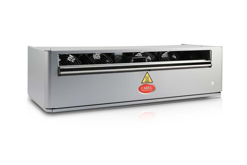
1. Introduzione
1.1 La testata ventilante per umidificatori isotermici CAREL heaterSteam, humiSteam, gaSteam diffonde il
vapore direttamente in ambiente in strutture che non hanno un sistema di distribuzione dell'aria.
Descrizione L'apparecchio deve essere installato a parete.
1.1.1 Modelli
Cod. Alimentazione Portata massima di vapore (kg/h)
VRDXL00001 230 Vac (rete elettrica) 45
Tab.1.a
1.1.2 Materiale a corredo
Descrizione Q.tà
Raccordo a Y per ingresso vapore 1
Tubo condensa (L = 800 mm/31.4 in), Ø int.=9 mm/0.35 in) 1
Fascetta metallica per tubo del vapore 4
Pressacavo 1
Tab.1.b
Nota: il tubo a Y ha l'ingresso con Ø 40 mm (1.57 in) e le due uscite con Ø 30 mm (1.18 in).
1.1.3 Accessori
Cod. Descrizione
1312368AXX Tubo condensa (Ø int.=9 mm/0.35 in)
1312365AXX Tubo del vapore (Ø int.=30 mm/1.18 in)
1312367AXX Tubo del vapore (Ø int.=40 mm/1.57 in)
Tab.1.c
1.1.4 Ricevimento/ identificazione
Dopo aver ricevuto l'apparecchio, controllare l'eventuale danneggiamento della scatola e se tutti i
componenti sono stati consegnati. Verificare dalla targhetta identificativa che il modello sia adatto per
l'installazione.
Nota: segnalare subito alla ditta di spedizione eventuali danni.
Immagazzinare l'apparecchio in un'area protetta, nelle condizioni previste nella tabella dati tecnici.
L'apparecchio è identificabile attraverso una targhetta tecnica posta nel retro che riporta il codice, il
modello, il numero di serie e altre informazioni.
Fig.1.a
VRDXL00001 +030222195 rel. 1.1 – 21.09.2018 1. Introduzione | 7ITA
1.1.5 Dimensioni - mm (in)
Fig.1.b
1.1.6 Struttura
Fig.1.c
Rif. Descrizione Rif. Descrizione
1 Uscita vapore 6 Morsettiera
2 Uscita aria 7 Portafusibile
3 Luce 8 Attacco scarico condensa (Ø 9 mm - 0.35 in)
4 Ventilatori 9 Attacco tubo vapore (2 x Ø 30 mm (1.18 in))
5 Termostato (klixon)
1.1.7 Principio di funzionamento
La testata ventilante è connessa all'alimentazione elettrica. Quando il vapore entra nella testata, dopo un
certo tempo il termostato raggiunge la temperatura di 50°C oppure l'uscita (morsetto J19) del controllo
c.pHC dà il consenso e i ventilatori si attivano. L'aria, prelevata posteriormente, fuoriesce mescolandosi con
il vapore e favorisce l'assorbimento in ambiente. La testata ventilante può funzionare con due logiche
differenti:
1. indipendentemente dall'umidificatore;
2. gestita direttamente dall'umidificatore (c.pHC). Il controllo ritarda l'avvio della testata dopo un tempo
prestabilito. Anche lo spegnimento può essere ritardato per effettuare l'asciugatura della testata
ventilante.
Nota: l'alimentazione a 230 Vac della testata ventilante va fornita esternamente con linea dedicata. Nel
caso di gestione da parte dell'umidificatore (con c.pHC), utilizzare il contatto J19 come nella figura
seguente.
8 | 1. Introduzione VRDXL00001 +030222195 rel. 1.1 – 21.09.2018ITA
1.1.8 Schema elettrico
Fig.1.d
Legenda
FU Fusibile FANS Ventilatori
T Termostato (klixon) L Luce
Nota: utilizzare lo schema precedente per alimentare in parallelo tramite l'umidificatore fino a 3
testate. Nel caso di 4 testate, utilizzare un relè esterno (non fornito), comandato a 24 Vac dal controllo
c.pHC. L'alimentazione delle 4 testate rimane esterna a 230 Vac.
Rimozione del ponticello
Nota: nel caso l'umidificatore non contenga il controllo c.pHC, rimuovere il ponticello. L'accensione
della testata ventilante avviene in base all'attivazione del termostato interno.
Svitare le viti per rimuovere il ponticello P.
Fig.1.e
La testata ventilante esce di fabbrica con il ponticello montato (=controllo della testata ventilante da
parte del controllo c.pHC dell'umidificatore).
VRDXL00001 +030222195 rel. 1.1 – 21.09.2018 1. Introduzione | 9ITA
2. Preparazione al montaggio
La testata ventilante deve essere montata a parete e collegata all’umidificatore per mezzo del tubo del
vapore. La lunghezza massima del tubo vapore è 4 m.
Nota: rispettare le distanze minime delle figure seguenti, per evitare che il flusso d’aria umidificata
investa persone, apparecchiature elettriche, controsoffitti e superfici fredde prima che il vapore sia
totalmente assorbito dall’ambiente.
Fig.2.a
Montaggio (tutte le quote in m[ft])
Rif. A parete
A >5[16.4]
B ≥1.7[5.5]
C+E ≥2.1[6.8]
D >0.5[1.6]
E ≤4[13.1]
Tab.2.a
2.1 2.1.1 Tubo del vapore
Prescrizioni
Durante l'installazione del tubo del vapore, seguire le seguenti avvertenze:
l usare esclusivamente tubi forniti da CAREL; tubi di altro materiale possono influenzare negativamente
il funzionamento del sistema;
l il tubo del vapore deve essere sostenuto da supporti (morsetti, staffe) in modo da non piegarsi e non
gravare sull'umidificatore. Un tubo riscaldato ha maggiore probabilità di piegarsi;
l il raggio di curvatura minimo del tubo del vapore è 5 volte il diametro interno;
l il tubo del vapore deve avere una pendenza minima per drenare la condensa verso l’umidificatore; in
ogni caso installare uno scarico condensa nel punto più basso del tubo del vapore;
l minimizzare la lunghezza del tubo vapore per minimizzare la dispersione di calore. Evitare la
formazione di sacche o sifoni nei quali la condensa può accumularsi;
l la formazione di una strozzatura (dovute a pieghe o attorcigliamenti) può causare un'eccessiva
contropressione nel cilindro dell'umidificatore quando l'unità è in funzione e quindi l'emissione
improvvisa di vapore.
Attenzione:
l non installare una valvola di arresto nel tubo vapore;
l al termine dei lavori, pulire la linea del vapore per rimuovere eventuali residui di contaminanti e
di lavorazione.
l l'esposizione della pelle a un getto di vapore può causare gravi ustioni;
l non stringere eccessivamente le fascette di fissaggio del tubo vapore (coppia max=180 N·cm).
10 | 2. Preparazione al montaggio VRDXL00001 +030222195 rel. 1.1 – 21.09.2018ITA
2.1.2 Tubo della condensa
Durante l'installazione del tubo della condensa, seguire le seguenti avvertenze:
l il tubo della condensa può essere riempito con acqua calda o vapore: il contatto con la pelle può
causare gravi ustioni;
l prevedere il collegamento a uno scarico secondo le vigenti normative nazionali e locali;
l il tubo della condensa deve avere una pendenza minima e deve confluire in un sifone alto 200 mm: il
sifone deve trovarsi almeno 300 mm sotto l'attacco della testata ventilante. In alternativa il tubo della
condensa può essere collegato all'attacco della vasca di raccolta condensa, posto nella parte superiore
dell'umidificatore;
l gli scarichi della condensa devono essere installati in tutti i punti più bassi e ogniqualvolta vi è un
passaggio da posizione orizzontale a verticale. La linea di scarico deve essere connessa con un
connettore "a T" e avere una pendenza minima. Il sifone deve trovarsi almeno 300 mm sotto l'attacco.
l verificare che linee di scarico condensa non siano otturate;
l non stringere eccessivamente le fascette di fissagio del tubo della condensa.
Attenzione: prima di avviare l'umidificatore riempire i sifoni con acqua.
Fig.2.b
VRDXL00001 +030222195 rel. 1.1 – 21.09.2018 2. Preparazione al montaggio | 11ITA
3. Montaggio
3.1 3.1.1 Smontaggio del coperchio
Operazioni
Per le operazioni di installazione della testata ventilante o per effettuare la manutenzione rimuovere il
preliminari coperchio dell’apparecchio secondo le istruzioni seguenti:
1. Sconnettere elettricamente la testata ventilante;
2. Svitare le 2 viti di fissaggio posizionate sulla superficie superiore del coperchio;
3. Estrarre il coperchio alzandolo con leggera rotazione in avanti per svincolarlo.
Fig.3.a
3.2 3.2.1 Montaggio a parete
Montaggio
Attenzione: montare la testata ventilante solo su parete in muratura.
Fissaggio della testata ventilante al supporto
Procedura:
Fig.3.c
Fig.3.b
1. Rimuovere il coperchio (vedere par. precedente). Togliere 2. Rimuovere le viti ed estrarre il supporto dalla testata.
le viti (A) e rimuovere il fondo (B).
Fig.3.d
Fig.3.e
12 | 3. Montaggio VRDXL00001 +030222195 rel. 1.1 – 21.09.2018ITA
3. Effettuare i fori a parete per fissare il supporto. 4.Utilizzare una livella per il montaggio.
Fig.3.f
5. Fissare la testata sul supporto e quindi montare il fondo (A), stringere le fascette per fissare i tubi del vapore (B) e il tubo
condensa. Collegare alla morsettiera il cavo dell'alimentazione elettrica. Infine rimontare il coperchio (C).
Nota: effettuare il collegamento del tubo vapore, del tubo condensa e del cavo elettrico seguendo le
avvertenze del cap. "Preparazione al montaggio".
VRDXL00001 +030222195 rel. 1.1 – 21.09.2018 3. Montaggio | 13ITA
4. Manutenzione e parti di ricambio
4.1 Componenti
Fig.4.a
Nr Descrizione Cod. ricambio
1 Ventilatore 230V VRDXLFAN01
2 Fusibile 800 mA T VRDXLFUS01
3 Termostato (klixon) VSDCLX0003
4 Luce 230 V VRDXLLUX01
5 Tubo della condensa 1312368AXX
6 Tubo del vapore (Ø40mm/1.57 in) 1312367AXX
7 Kit guarnizioni VSDGUAR000
Tab.4.a
4.2 Sostituzione Nota: la manutenzione dell’umidificatore deve essere effettuata dal Servizio Tecnico di Assistenza
CAREL oppure da personale professionalmente qualificato.
componenti
Attenzione: prima di effettuare qualunque operazione:
l togliere l'alimentazione elettrica all'umidificatore portando l'interruttore generale dell'impianto su
spento (OFF);
l rimuovere il coperchio della testata ventilante (vedere paragrafo precedente);
l sostituire il componente guasto;
l terminate le operazioni di manutenzione, rimontare i componenti operando nel senso inverso
ripetto a quanto descritto.
4.2.1 Ventilatore
Dopo aver rimosso il coperchio della testata ventilante (vedere il cap. "Montaggio"):
A. svitare le viti che bloccano il pannello posteriore con le feritoie;
B. togliere i connettori elettrici;
C. svitare e rimuovere le viti per sostituire il ventilatore.
14 | 4. Manutenzione e parti di ricambio VRDXL00001 +030222195 rel. 1.1 – 21.09.2018ITA
Fig.4.b
4.2.2 Luce/termostato/fusibile
Dopo aver rimosso il coperchio della testata ventilante (vedere paragrafo precedente), per procedere alla
sostituzione di:
l luce (A): premere le alette laterali per sfilarla, sconnettere i fili dalla morsettiera;
l termostato (B): sconnettere i connettori elettrici e con una chiave a tubo svitare i dadi di fissaggio;
l fusibile: svitare il portafusibile (C).
Fig.4.c
4.2.3 Anomalie e rimedi
Problema Causa Rimedio
l Il ventilatore si attiva solo quando
l Verificare l'alimentazione
l'umidificatore genera vapore
l Verificare il fusibile
Ventilatore non funziona l La testata ventilante non è
l Verificare che l'umidificatore
alimentata
funzioni e vi sia richiesta di umidità
l Ventilatore guasto
l Verificare che il tubo vapore non sia
piegato
l Linea vapore installata in modo
l Sifone installato correttamente, non
errato, non arriva sufficiente vapore
Ventilatore non funziona, ma otturato
l Termostato bloccato
l'umidificatore sta generando vapore l Verificare che quando il termostato
l Testata ventilante non alimentata
è chiuso vi sia continuità elettrica
l Fusibile guasto
l Verificare il cavo elettrico di
collegamento all'umidificatore
l Testata ventilante non è montata a
Testata ventilante spruzza gocce di livello perfettamente orizzontale
l Controllare
condensa l Ostruzione della presa di
aspirazione posteriore
Tab.4.b
VRDXL00001 +030222195 rel. 1.1 – 21.09.2018 4. Manutenzione e parti di ricambio | 15ITA
5. Caratteristiche tecniche
Descrizione Valore o intervallo
Alimentazione (V~) 230 Vac (+5%, -10%), 50/60 Hz
Ingresso vapore ϕ (mm) (2 x) 30
Scarico condensa ϕ (mm) 9
Portata massima di vapore (kg/h) 45
Grado di protezione IP20
Temperatura/ umidità di immagazzinamento -10.... +70 °C / 10... 80 rH% non condensante
Potenza nominale (W) 120
Portata aria nominale (m3/h) 576
Livello sonoro (campo aperto, alla massima velocità ad 1 m
50
di distanza (dB)
Temperatura / umidità di funzionamento 1... 50 °C / 10... 80 rH% non condensante
Dimensioni (mm/in) 687 x 278 x 194 (27.4 x 10.9 x 7.6)
Peso (kg) 9.5
IEC 60335-1, Edition 5.2 dated 2016-05
IEC 60335-2 98: 2002 (Second edition) + A1: 2004+A2: 2008
Conformità CE: direttive: 2014/35/EU, 2014/30/EU
IEC 60335-1 2010 (Fifth edition) incl. Corr 1: 2010 and Corr2:
2011+ A1: 2013
Conformità UL: UL 998/CSA C22.2 No 104-R1999
5.0.1 Tabelle accoppiamento umidificatori
humiSteam
uscita umidificatore ø mm ---> 22 /30 (0.9")/(1.2”) 30 (1.2”) 40 (1.6”) 2x 40 (1.6”) 4x 40 (4x 1.6”)
capacità umidificatore kg/h ---> 1 3 5 8 9 10 15 18 25 35 45 65 90 130
umidificatore ---> UE001 UE003 UE005 UE008 UE009 UE010 UE015 UE018 UE025 UE035 UE045 UE065 UE090 UE130
VSDU0A0003 (≤18kg/h) 1 1 1 1 1 1 1 1
VRDXL00001 (≤45kg/h) 1 1 1 2 2 4
Tab.5.a
heaterSteam
uscita umidificatore ø mm ---> 30 (1.2”) 40 (1.6”) 2x 40 (1.6”)
capacità umidificatore kg/h ---> 2 4 6 10 13 20 27 40 53 60 80
umidificatore ---> UR002 UR004 UR006 UR010 UR013 UR020 UR027 UR040 UR053 UR060 UR080
VSDU0A0003 (≤18kg/h) 1 1 1 1 1
VRDXL00001 (≤45kg/h) 1 1 1 2 2 2
Tab.5.b
gaSteam
uscita umidificatore ø mm ---> 2x 40 (1.6”) 4x 40 (4x 1.6”)
capacità umidificatore kg/h ---> 45 90 180
umidificatore ---> UG045 UG090 UG180
VSDU0A0003 (≤18kg/h)
VRDXL00001 (≤45kg/h) 1* 2 4
Tab.5.c
(*) utilizzare il raccordo a Y cod. UEKY40X400 per convogliare le 2 uscite del vapore dell'umidificatore in
un unico tubo di Ø 40 mm.
16 | 5. Caratteristiche tecniche VRDXL00001 +030222195 rel. 1.1 – 21.09.2018ENG
humidifier, unless specifically indicated in the user manual.
Do not drop, hit or shake the humidifier, as the inside parts
! l
and the linings may be irreparably damaged.
CAREL adopts a policy of continual development. Consequently,
CAREL reserves the right to make changes and improvements to
CAREL Industries humidifiers are advanced products, whose any product described in this document without prior warning.
operation is specified in the technical documentation supplied The technical specifications shown in the manual may be changed
with the product or can be downloaded, even prior to purchase, without prior warning. The liability of CAREL in relation to its
from the website www.carel.com. Each CAREL product, in relation products is specified in the CAREL general contract conditions,
to its advanced level of technology, requires published on the website www.carel.com and/or by specific
setup/configuration/programming to be able to operate in the agreements with customers; specifically, to the extent where
best possible way for the specific application. Failure to complete allowed by applicable legislation, in no case will CAREL, its
such operations, which are required/indicated in the user manual, employees or subsidiaries/affiliates be liable for any lost earnings
may cause the final product to malfunction; CAREL accepts no or sales, losses of data and information, costs of replacement goods
liability in such cases. The customer (manufacturer, developer or or services, damage to things or people, downtime or any direct,
installer of the final equipment) accepts all liability and risk indirect, incidental, actual, punitive, exemplary, special or
relating to the configuration of the product in order to reach the consequential damage of any kind whatsoever, whether
expected results in relation to the specific final installation and/or contractual, extra-contractual or due to negligence, or any other
equipment. CAREL may, based on specific agreements, act as a liabilities deriving from the installation or use of the product, even
consultant for the installation/commissioning/use of the unit, if CAREL or its subsidiaries/affiliates are warned of the possibility
however in no case does it accept liability for the correct of such damage.
operation of the humidifier and the final installation if the
warnings or suggestions provided in this manual or in other
DISPOSAL
product technical documents are not heeded. In particular, as well
as observing the above warnings and suggestions, the following
warnings must be observed for correct use of the product:
l DANGER OF ELECTRIC SHOCK: the humidifier contains live
electrical components. Disconnect the mains power supply The humidifier is made up of metal parts and plastic parts. In
before accessing inside parts or during maintenance and reference to European Union directive 2002/96/EC issued on 27
installation. January 2003 and related national legislation, please note that:
l DANGER OF WATER LEAKS: the humidifier automatically and
1. WEEE cannot be disposed of as municipal waste and such
constantly fills/drains certain quantities of water. Malfunctions
waste must be collected and disposed of separately;
in the connections or in the humidifier may cause leaks. 2. the public or private waste collection systems defined by local
Important: legislation must be used. In addition, the equipment can be
l Environmental and power supply conditions must conform returned to the distributor at the end of its working life when
to the values specified on the product rating labels. buying new equipment;
l Only qualified personnel who are aware of the necessary 3. the equipment may contain hazardous substances: the
precautions and able to perform the required operations improper use or incorrect disposal of such may have negative
correctly may install, operate or carry out technical service effects on human health and on the environment;
on the product. 4. the symbol (crossed-out wheeled bin) shown on the product
l Only water with the characteristics indicated in this manual or on the packaging and on the instruction sheet indicates that
must be used to produce the spray. the equipment has been introduced onto the market after 13
l All operations on the product must be carried out August 2005 and that it must be disposed of separately;
according to the instructions provided in this manual and 5. in the event of illegal disposal of electrical and electronic
on the labels applied to the product. Any uses or waste, the penalties are specified by local waste disposal
modifications that are not authorised by the manufacturer legislation.
are considered improper. CAREL declines all liability for any
such unauthorised use. Warranty on materials: 2 years (from production date, excluding
l Do not attempt to open the appliance in any way other consumables).
than described in the manual. Approval: the quality and safety of CAREL products are guaranteed
l Observe the standards in force in the place where the by the ISO 9001 certified design and production system, as well
humidifier is installed.
l Keep the humidifier out of the reach of children and as by the CE mark:
animals.
l Do not install and use the product near objects that may be Key to the symbols:
damaged when in contact with water (or condensate).
CAREL declines all liability for direct or indirect damage Dangerous voltage.
following water leaks from the humidifier. Caution, hot surface.
l Do not use corrosive chemicals, solvents or aggressive
Risk of burns due to contact with steam.
detergents to clean the inside and outside parts of the
VRDXL00001 +030222195 rel. 1.1 – 21.09.2018 |3ENG
Important: to bring critical issues to the attention of those The humidifier and the blower use hot steam for
using the product. humidification. Exposure of the skin to the hot steam may
Note: to focus attention on important topics; in particular the cause severe burns. Wear personal protective equipment
practical application of the various product functions. when working near steam.
The system’s components (including the humidifier cylinder
Important: this product is to be integrated and/or
and blower) can reach temperatures of up to 100°C during
incorporated into the final apparatus or equipment.
operation. Contact with hot surfaces can cause serious burns.
Verification of conformity to the laws and technical standards
Switch off the humidifier and allow it to cool down before
in force in the country where the final apparatus or equipment
starting any work on the system.
will be operated is the manufacturer’s responsibility. Before
delivering the product, Carel has already completed the Ensure compliance with all national and local laws and
checks and tests required by the relevant European directives regulations regarding the safety of low voltage equipment
and harmonised standards, using a typical test setup, which installations, requirements regarding installation of the steam
however cannot be considered as representing all possible and condensate drain lines, as well as the requirements for
conditions of the final installation. correct use of tools and personal protective equipment.
Only use this appliance for the purposes specified by the
manufacturer. Do not modify or replace the components
unless recommended by the manufacturer, as this may cause
hazards for the user or third parties and/or damage to objects.
General warnings
l The blower and the humidifier can only be installed and
serviced out by qualified personnel who have read and
understood this manual and the humidifier manual.
Knowledge and understanding of the contents of this manual is
an essential requirement to protect personnel against any kind
of danger, to prevent hazardous operation and to allow the
unit to operate safely.
l All of the procedures described in this manual must be carried
out by personnel who have been suitably trained and
authorised by the customer.
l All personnel working with CAREL humidifiers and blowers
must know and comply with all occupational health and safety
regulations.
l The blower is intended exclusively for air humidification in the
specified operating conditions.
l In order to operate the blower according to its intended use,
all of the information contained in this manual and in particular
the safety instructions must be scrupulously observed.
l This appliance can be used by children over the age of 8 and
by persons with reduced physical, sensory or mental
capabilities or lack of experience if they have been given
supervision or instruction concerning use of the appliance in a
safe way.
l Children must not play with the appliance.
l Cleaning and maintenance must not be carried out by children
unless they are supervised by an adult.
Fundamental safety rules
Before carrying out any maintenance, disconnect the blower
and the humidifier from the power supply by moving the
main system switch to “off”.
The humidifier and the blower can only be connected to the
power supply after the installation operations have been
completed and verified as having been carried out correctly,
and the covers and panels have been installed and securely
fastened.
The humidifier and the blower use hot steam for
humidification. Exposure of the skin to the hot steam may
cause severe burns. Wear personal protective equipment
when working near steam.
4| VRDXL00001 +030222195 rel. 1.1 – 21.09.2018ENG Index 1. INTRODUCTION 7 1.1 Description 7 2. PREPARING FOR ASSEMBLY 10 2.1 Requirements 10 3. ASSEMBLY 12 3.1 Preliminary operations 12 3.2 Assembly 12 4. MAINTENANCE AND SPARE PARTS 14 4.1 Components 14 4.2 Component replacement 14 5. TECHNICAL SPECIFICATIONS 16 VRDXL00001 +030222195 rel. 1.1 – 21.09.2018 |5
ENG

1. Introduction
1.1                           The blower for CAREL heaterSteam, humiSteam, gaSteam isothermal humidifiers distributes steam
                              directly into rooms in structures that do not feature an air distribution system. The appliance must be
Description                   wall-mounted.

                              1.1.1 Models
                               P/N                    Power supply              Maximum steam flow-rate (kg/h)
                               VVRDXL00001            230 Vac (mains)           45
                                                                                                                              Tab.1.a

                              1.1.2 Material supplied
                               Description                                                                                       Qty
                               Y connection pipe for steam input                                                                 1
                               Condensate hose (L = 800 mm/31.4 in), ID = 9 mm/0.35 in)                                          1
                               Metal clamp for steam hose                                                                        4
                               Cable gland                                                                                       1
                                                                                                                              Tab.1.b

                                 Note: the "Y" connection pipe has input with ID 40mm (1.57in) and 2 outputs with ID 30 mm (1.18in).

                              1.1.3 Accessories
                               P/N                        Description
                               1312368AXX                 Condensate hose (ID = 9 mm/0.35 in)
                               1312365AXX                 Steam hose (ID = 30 mm/1.18 in)
                               1312367AXX                 Steam hose (ID = 40 mm/1.57 in)
                                                                                                                              Tab.1.c

                              1.1.4 Receiving/identification
                              After having received the appliance, check that the box is not damaged and all of the components have
                              been delivered. Verify on the identification rating plate that the model is suitable for the required
                              installation.
                                 Note: immediately report any damage to the carrier.
                              Store the appliance in a protected area in the conditions specified in the technical data table.
                              The appliance can be identified via the rating plate on the rear, which shows the part number, model,
                              serial number and other information.

                              Fig.1.a

VRDXL00001 +030222195 rel. 1.1 – 21.09.2018                                                                  1. Introduction | 7
ENG
1.1.5 Dimensions - mm (in)
Fig.1.b
1.1.6 Structure
Fig.1.c
Ref. Description Ref. Description
1 Steam outlet 6 Terminal block
2 Air outlet 7 Fuse holder
3 Light 8 Condensate outlet fitting (Ø 9 mm - 0.35 in)
4 Fans 9 Steam hose fitting (2 X Ø 30 mm (1.18 in))
5 Thermostat (klixon)
1.1.7 Operating principle
The blower is connected to the power supply. When steam enters the blower, after a certain time either
the thermostat detects a temperature of 50°C or the output (terminal J19) on the c.pHC controller gives
the signal and the fans are activated. The air, taken in from the rear, is mixed with steam before being
delivered into the room, where it is easily absorbed. The blower features two different types of
operating logic:
1. independent of the humidifier;
2. managed directly by the humidifier (c.pHC). The controller delays blower activation for a set time.
Deactivation can also be delayed to allow the blower to dry.
Note: the 230 Vac power supply to the steam blower is supplied externally by a dedicated line. If the
humidifier has to manage the steam blower (with c.pHC controller), use the J19 contact as in the
following drawing.
8 | 1. Introduction VRDXL00001 +030222195 rel. 1.1 – 21.09.2018ENG
1.1.8 Wiring diagram
Fig.1.d
Key
FU Fuse FANS Fans
T Thermostat (klixon) L Light
Note: use the previous drawing to supply in parallel up to 3 steam blowers. With 4 steam blowers,
use an external relay (not supplied), managed by a 24 Vac command from the c.pHC controller. The
230 Vac power supply to the 4 steam blowers remains external.
Removing the jumper
Note: If the humidifier is not fitted with the c.pHC controller, remove the jumper. The blower will be
activated by the built-in thermostat.
Unscrew the screws to remove the jumper P.
Fig.1.e
The blower leaves the factory with the jumper inserted (= blower managed by the c.pHC controller on
the humidifier).
VRDXL00001 +030222195 rel. 1.1 – 21.09.2018 1. Introduction | 9ENG
2. Preparing for assembly
The blower must be mounted or on the wall and connected to the humidifier via the steam hose.
The maximum length of the steam hose is 4 m.
Note: observe the minimum distances shown in the following figures to prevent the flow of
humidified air from coming into contact with people, electrical equipment, false-ceilings and cold
surfaces before the steam is totally absorbed by the atmosphere.
Fig.2.a
Mounting (all dimensions in m[ft])
Ref. Wall
A >5[16.4]
B ≥1.7[5.5]
C+E ≥2.1[6.8]
D >0.5[1.6]
E ≤4[13.1]
Tab.2.a
2.1 2.1.1 Steam hose
Requirements
Follow these instructions when installing the steam hose:
l only use hoses supplied by CAREL; hoses made from other materials may adversely affect operation of
the system;
l the steam hose must be secured by supports (clamps, brackets) so that it does not bend and does not
weigh on the humidifier. A hot hose is more likely to bend;
l the minimum radius of curvature of the steam hose is 5 times the inside diameter;
l the steam hose must have a minimum slope in order to drain condensate back to the humidifier; in
any case, always install a condensate drain at the lowest point on the steam hose;
l minimise the length of the steam hose so as to reduce heat loss. Avoid the formation of pockets or
traps where condensate may accumulate;
l choking (due to bends or twisting of the hose) can cause excessive back-pressure in the humidifier
cylinder when the unit is operating and consequently sudden steam outlet.
Important:
l do not install a stop valve in the steam hose;
l when installation is complete, flush the steam line to remove any contaminants and processing
residues.
l exposure of the skin to a jet of hot steam may cause severe burns;
l do not over-tighten the hose clamps (max. torque=180 N·cm).
10 | 2. Preparing for assembly VRDXL00001 +030222195 rel. 1.1 – 21.09.2018ENG
2.1.2 Condensate hose
Follow these instructions when installing the condensate hose:
l the condensate hose may be filled with hot water or steam: contact with the skin can cause serious
burns;
l connect the hose to a drain in accordance with national and local regulations in force;
l the condensate hose must have a minimum downward slope and must flow into a 200 mm high drain
trap: the drain trap must be at least 300 mm below the connection to the blower.
l condensate drains must be installed at all the lowest points and wherever the drain line goes from
horizontal to vertical. The drain line must be connected to a “T” connector and have a minimum
downward slope. The drain trap must be at least 300 mm below the connection.
l make sure that the condensate drain lines are not blocked;
l do not over-tighten the clamps on the condensate hose.
Important: before starting the humidifier, fill the drain traps with water.
Fig.2.b
VRDXL00001 +030222195 rel. 1.1 – 21.09.2018 2. Preparing for assembly | 11ENG
3. Assembly
3.1 3.1.1 Removing the cover
Preliminary
For steam blower installation or maintenance, remove the cover from the appliance as described below:
operations
1. Disconnect the blower from the power supply;
2. Unscrew the two fixing screws placed on the top of the cover;
3. Pull the cover up by slightly turning it forward to release it.
Fig.3.a
3.2 3.2.1 Wall-mounting
Assembly
Important: mount the blower only on masonry walls.
Fixing the blower to the support
Procedure:
Fig.3.c
Fig.3.b
1. Remove the cover (see previous paragraph). Unscrew 2. Remove the screws and extract the support from the
the screws (A) and remove the bottom panel (B). blower.
Fig.3.d
Fig.3.e
3. Make the holes in the wall to fix the support. 4. Use a spirit level for mounting
12 | 3. Assembly VRDXL00001 +030222195 rel. 1.1 – 21.09.2018ENG
Fig.3.f
5. Fix the blower to the support and then mount the bottom panel (A), tighten the metal clamps to fix the steam hoses
(B) and then condensate hose. Connect the power supply cable to the terminal block. At the end mount the cover (C)
again.
Note: install the steam hose, the condensate hose and the power cable following the steps described
in the previous paragraph and the notes in chap. "Preparing for assembly".
VRDXL00001 +030222195 rel. 1.1 – 21.09.2018 3. Assembly | 13ENG
4. Maintenance and spare parts
4.1
Components
Fig.4.a
No. Description Spare part no.
1 Fan 230 V VRDXLFAN01
2 Fuse 800 mA T VRDXLFUS01
3 Thermostat (klixon) VSDCLX0003
4 Light 230 Vac VRDXLLUX01
5 Condensate hose 1312368AXX
6 Steam hose (Ø 40 mm/1.57 in) 1312367AXX
7 Gasket kit VSDGUAR000
Tab.4.a
4.2 Component Note: Maintenance on the humidifier must be carried out by CAREL Technical Service or professionally
qualified personnel.
replacement Important: before proceeding:
l disconnect power to the humidifier by turning the main system switch to OFF;
l remove the cover from the blower (see the previous paragraph);
l replace the faulty component;
l once having completed maintenance, reassemble the components by working in reverse to the
steps described above.
4.2.1 Fan
After having removed the blower cover (see chap. “Assembly”):
A. remove the screws that secure the rear panel with the slits;
B. unplug the electrical connectors;
C. unscrew and remove the screws to replace the fan.
14 | 4. Maintenance and spare parts VRDXL00001 +030222195 rel. 1.1 – 21.09.2018ENG
Fig.4.b
4.2.2 Light/thermostat/fuse
After having removed the blower cover (see the previous paragraph), for replacement proceed as follows:
l light (A): press the tabs at the side to remove it, disconnect the wires from the terminal block;
l thermostat (B): disconnect the electrical connectors and unscrew the fixing nuts using a socket wrench;
l fuse: unscrew the fuse holder (C).
Fig.4.c
4.2.3 Troubleshooting
Problem Cause Solution
l Check power supply
l The fan is only activated when the
l Check fuse
humidifier generates steam Make sure that the humidifier is
The fan is not working l
l The blower is not powered
operating and humidity production is
l Faulty fan
required
l Make sure that the steam hose is not
l Steam line installed incorrectly, not bent
enough steam reaches the blower l Drain trap installed correctly and not
The fan is not working but the
l Thermostat stuck blocked
humidifier is generating steam
l The blower is not powered l Verify that when the thermostat is closed
l Faulty fuse there is electrical continuity
l Check the humidifier connection cable
l Blower not mounted perfectly
Blower sprays droplets of
horizontally l Check
condensate
l Rear air intake blocked
Tab.4.b
VRDXL00001 +030222195 rel. 1.1 – 21.09.2018 4. Maintenance and spare parts | 15ENG
5. Technical specifications
Description Value or range
Power supply (V~) 230 Vac (+ 5%, -10%), 50/60 Hz
Steam inlet ϕ (mm) (2 x) 30
Condensate drain ϕ (mm) 9
Maximum steam flow-rate (kg/h) 45
Ingress protection IP20
Storage temperature/humidity (°C) -10.... +70°C / 10...80 rH% non-condensing
Nominal power (W) 120
Nominal air flow rate (m3/h) 576
Sound level (open field at maximum speed and a distance
50
of 1 m) (dB)
Operating temperature/humidity (°C/rH%) 1... 50°C / 10...80 rH% non-condensing
Dimensions (mm/in) 687 x 278 x 194 (27.0 x 10.9 x 7.6)
Weight (kg) 9.5
IEC 60335-1, Edition 5.2 dated 2016-05
IEC 60335-2 98: 2002 (Second edition) + A1: 2004+A2: 2008
CE conformity: Directives: 2014/35/EU, 2014/30/EU
IEC 60335-1 2010 (Fifth edition) incl. Corr 1: 2010 and Corr2:
2011+ A1: 2013
UL conformity: UL 998/CSA C22.2 No 104-R1999
5.0.1 Humidifier connection tables
humiSteam
humidifier outlet ø mm ---> 22 /30 (0.9")/(1.2”) 30 (1.2”) 40 (1.6”) 2x 40 (1.6”) 4x 40 (4x 1.6”)
humidifier capacity kg/h ---> 1 3 5 8 9 10 15 18 25 35 45 65 90 130
humidifier ---> UE001 UE003 UE005 UE008 UE009 UE010 UE015 UE018 UE025 UE035 UE045 UE065 UE090 UE130
VSDU0A0003 (≤18kg/h) 1 1 1 1 1 1 1 1
VRDXL00001 (≤45kg/h) 1 1 1 2 2 4
Tab.5.a
heaterSteam
humidifier outlet ø mm ---> 30 (1.2”) 40 (1.6”) 2x 40 (1.6”)
humidifier capacity kg/h ---> 2 4 6 10 13 20 27 40 53 60 80
humidifier ---> UR002 UR004 UR006 UR010 UR013 UR020 UR027 UR040 UR053 UR060 UR080
VSDU0A0003 (≤18kg/h) 1 1 1 1 1
VRDXL00001 (≤45kg/h) 1 1 1 2 2 2
Tab.5.b
gaSteam
humidifier outlet ø mm ---> 2x 40 (1.6”) 4x 40 (4x 1.6”)
humidifier capacity kg/h ---> 45 90 180
humidifier ---> UG045 UG090 UG180
VSDU0A0003 (≤18kg/h)
VRDXL00001 (≤45kg/h) 1(*) 2 4
Tab.5.c
(*) use a "Y" pipe cod. UEKY40X400 to route the two steam outputs into the same pipe with Ø 40 mm.
16 | 5. Technical specifications VRDXL00001 +030222195 rel. 1.1 – 21.09.2018ENG VRDXL00001 +030222195 rel. 1.1 – 21.09.2018 | 17
Delete this text and replace it with your own content.

                                                                                                                           VRDXL00001 +030222195 rel. 1.1 - 21.09.2018

CAREL INDUSTRIES S.p.A. - Headquarters
Via dell'Industria, 11
                                                  CAREL can accept no responsibility for possible errors in this manual.
35020 Brugine - Padova (Italy)                    CAREL reserves the right to modify its products without notice.
Tel. (+39) 049.9716611
Fax (+39) 049.9716600
email: carel@carel.com - www.carel.com
Puoi anche leggere